PROSPERITY GROUP Traxon e:cue LIGHTDRIVE+ WiFi User manual

AM477420038
e:cue LIGHTDRIVE+ WiFi
Installation Guide
Edition:
06.02.23 [EN_LIGHTDRIVEplusWiFi_Installation_v2p1]
Published by:
Traxon Technologies Europe GmbH
Karl-Schurz-Strasse 38
33100 Paderborn, Germany
©2023 Traxon Technologies Europe GmbH
All rights reserved
Read the Installation Guide and the Safety Instructions carefully.
Subject to modication without prior notice. Typographical and
other errors do not justify any claim for damages. Modication of
the product is prohibited.
This document is designed for electricians and system
administrators of the product.
All product names and trademarks mentioned in this manual are
trademarks of their respective owners.
Except for internal use, relinquishment of the instructions to a
third party, duplication in any type or form - also extracts - as
well as exploitation and / or communication of the contents is not
permitted.
Traxon Technologies Europe GmbH
Sales Operations
Karl-Schurz-Str. 38
33100 Paderborn, Germany
+49 5251 54648-0
Downloads and more information at:
www.ecue.com

WWW.TRAXON-ECUE.COM ©2023 traxon technologies. All rights reserved. Installation Guide 02/23 Sheet: 02 / 13
LIGHTDRIVE+ WiFi — Installation Guide | Table of Contents
Table of Contents
1 Safety instructions 03
1.1 Symbols 03
1.2 General instructions 03
2 General remarks 03
2.1 Transport 03
2.2 Unpacking 03
2.3 Warranty regulations 03
2.4 Maintenance and Repair 03
2.5 Disposal 04
2.6 Support 04
2.7 Further information 04
3 General device description 04
3.1 Delivery content 05
3.2 Optional accessories 05
4 Productspecications 05
5 Connectorsandinterfaces 07
5.1 User & USB interfaces 07
5.2 Connections 08
6 DIP switches 08
6.1 Control all Zones via Zone A 09
7 Powersupply 09
8 Low-sideswitches&Digitaldrycontacts 09
9 Mounting 10
10 Dismounting 10
11 Certications 11
12 Dimensions 11
13 Further guides 12
14 Trouble shooting 12
15 FAQ 13

WWW.TRAXON-ECUE.COM ©2023 traxon technologies. All rights reserved. Installation Guide 02/23 Sheet: 03 / 13
1 Safety instructions
Read the safety instructions, provided in a separate manual, carefully. Make sure that the environmental,
mounting, and installation prerequisites are met. This manual should be kept at a safe place and in reach of
the device.
1.1 Symbols
!
The exclamation mark warns about possible
damage of the device itself, to connected devices,
and to the user.
i
The information symbol gives general hints and
informs about handling and procedures for use of
the device.
1.2 General instructions
2 General remarks
2.1 Transport
Only transport the device in its original packaging. This protects the device from damage.
2.2 Unpacking
Only unpack the e:cue LIGHTDRIVE+ WiFi at its installation location. To protect the device against
condensation water, unpack it and wait until all moisture remaining in the device has evaporated.
Condensation can occur when the device is moved from a cold to a warm location. Keep the packaging for
use in case of further transport. Inspect all parts for completeness regarding chapter „3.1 Delivery content“
on page 05. If there is apparent damage to the device or parts are missing from the delivery scope, please
contact the Traxon e:cue Support service.
2.3 Warranty regulations
Depending on the product, warranty regulations are of dierent duration. The warranty time is usually noted
in the quote and in the order conrmation. See www.traxon-ecue.com/terms-and-conditions for details. Legal
warranty regulations apply in any case.
2.4 Maintenance and Repair
This device requires no maintenance.
!
— The Ethernet port of the LIGHTDRIVE+ WiFi is not
designed for inter-building connections. Use the
LIGHTDRIVE+ WiFi only with intra-building networks.
i
— If safety instructions are missing, please contact Traxon
e:cue to receive a new copy.
!
— Before dismounting, appropriate measures must be taken
to protect the respective components against damage
caused by electrostatic discharge (ESD protection).
— Do not try to repair the device. Return it to your Traxon
e:cue distributor for replacement or repair.
LIGHTDRIVE+ WiFi — Installation Guide | Safety instructions
content

WWW.TRAXON-ECUE.COM ©2023 traxon technologies. All rights reserved. Installation Guide 02/23 Sheet: 04 / 13
2.5 Disposal
The proper disposal of packing materials and of the device is the responsibility of the respective user and for
his account; in all other matters, the retrieval obligation for packing materials and the device is subject to the
statutory regulations.
2.6 Support
In case of technical problems or questions regarding installation and repair please contact:
Traxon Technologies Europe GmbH
Customer Service
Karl-Schurz-Str. 38
33100 Paderborn, Germany
+49 (5251) 54648-0
2.7 Further information
For further product information, such as the conguration guide and the onboarding guide, check
www.traxon-ecue.com.
3 General device description
LIGHTDRIVE+ WiFi fuses dynamic lighting control with a sophisticated design. The wall-mounted user
terminal is able to output various scenes and eects in dierent zones which are set-up via the
LIGHTDRIVE+ app. No matter what kind of location you have in mind: bars and restaurants, shops and malls,
museums, reception areas ... For any purpose of any scale, be it small or mid-size, LIGHTDRIVE+ WiFi is the
easy and straightforward solution for lighting control. The user terminal serves as a standalone DMX512
controller. The focal point of user interaction is the so called Jog Wheel. With this control knob, scenes,
zones and eects, such as speed and brightness, can be adjusted in a blink of an eye. The user terminal itself
shows a clear and minimalistic design with a high quality glass front panel. LIGHTDRIVE+ WiFi is compatible
with all monochrome, dynamic white, RGB und RGBW LED xtures.
Main features:
yState-of-the-art user interface with elegant appearance
ySet-up via LIGHTDRIVE+ app
yFor monochrome, dynamic white, RGB and RGBW LED xtures
yTwo DMX outputs, divided in 3 zones
y8 scenes in each of the 3 predened zones
yPre-dened FX eects
yIntegrated scheduler for time trigger
yIntegrated proximity sensor
y2 low-side switches and 2 dry inputs for integration into 3rd party systems
Batteries and technical appliances must not be disposed of
with domestic waste, but should be handed in at the
appropriate collection and disposal points.
LIGHTDRIVE+ WiFi — Installation Guide | General device description
content

WWW.TRAXON-ECUE.COM ©2023 traxon technologies. All rights reserved. Installation Guide 02/23 Sheet:05/13
3.1 Delivery content
Delivery content for the e:cue LIGHTDRIVE+ WiFi (AM477420038):
1. e:cue LIGHTDRIVE+ WiFi
2. Device plugs
3. Safety instructions
4. Welcome card
3.2 Optional accessories
yPower Supply 15W 12V DIN rail (AM3137600HA)
4 Product specications
Productspecications
Dimensions
(W x H x D)
80 x 160 x 30 mm /
3.15 x 6.30 x 1.18 inch
Weight 188 g / 0.41 lb
Power supply PoE IEEE 802.3af, polarity-
independent
or 12 V DC SELV
Power consumption typ. 4.5 W,
max. 6 W (all LEDs 100 % white),
on device plug
Operating temperature 0 ... 35 °C / 32 ... 95 °F
Storage temperature 0 ... 50 °C / 32 ... 122 °F
Op. / storage humidity 0 … 80% RH, non-condensing
Protection class IP20
Installation Indoor installation only,
Intra building connections only
Electrical safety class SELV
Housing PC/ABS, glass
Mounting Wall mount housing, suitable for most
international in-wall mounted boxes
Certi cates CE, ETL, FCC, UKCA
Real time clock with capacitor backup, holds time for
~1 h
Interfacespecications
User interfaces (UI) 12 x capacitive touch key
1 x jog wheel with switch
System interfaces 3 x DIP switch
1 x Ethernet 10/100 Mbit/s, on device
plug, max. cable length: 65 m,
for synchronization of multiple devices
only
1 x USB 2.0 micro USB-B,
for update only
DMX outputs 2 x DMX512, on device plug
Fixture types Monochrome (1 channel)
Dynamic White (2 channels)
RGB (3 channels)
RGBW (4 channels)
Low-side switches 2 x 24 V DC, max. 3 A, ON resistance 50
mΩ, normally open, galvanically isolated,
overload protected, on device plug
Digital dry contacts 2 x inputs, 5 V DC contact supply, on
device plug,
Input high threshold voltage:
VIHmin = 2.5 V
Input low threshold voltage:
VILmax = 1.2 V
Typ. input threshold voltage:
VSW(typ) = 1.5 V
Input voltage max.: VINmax = 15 V
Digital inputs supply For dry contacts
Use 5 V DC from device (pin 7)
VSUP = 5 V DC
max. 15 mA
Typ. current when sourcing all 2 ports:
Ityp = 12 mA
Device plugs Push-in spring connection plug,
Stripping length: 6 mm
Major diameter of isolated cable max.
2 mm
Cable cross-section:
solid: 0.14 ... 0.5 mm²
fl exible: 0.2 ... 0.5 mm²
WiFi RF frequencies: 2.4 ... 2.473 GHz,
IEEE 802.11 b/g/n
Sensors Proximity sensors for UI activation
LIGHTDRIVE+ WiFi — Installation Guide | Product specications
content

WWW.TRAXON-ECUE.COM ©2023 traxon technologies. All rights reserved. Installation Guide 02/23 Sheet: 06 / 13
Productspecications
Dimensions
(W x H x D)
80 x 160 x 30 mm /
3.15 x 6.30 x 1.18 inch
Weight 188 g / 0.41 lb
Power supply PoE IEEE 802.3af, polarity-
independent
or 12 V DC SELV
Power consumption typ. 4.5 W,
max. 6 W (all LEDs 100 % white),
on device plug
Operating temperature 0 ... 35 °C / 32 ... 95 °F
Storage temperature 0 ... 50 °C / 32 ... 122 °F
Op. / storage humidity 0 … 80% RH, non-condensing
Protection class IP20
Installation Indoor installation only,
Intra building connections only
Electrical safety class SELV
Housing PC/ABS, glass
Mounting Wall mount housing, suitable for most
international in-wall mounted boxes
Certi cates CE, ETL, FCC, UKCA
Real time clock with capacitor backup, holds time for
~1 h
Interfacespecications
User interfaces (UI) 12 x capacitive touch key
1 x jog wheel with switch
System interfaces 3 x DIP switch
1 x Ethernet 10/100 Mbit/s, on device
plug, max. cable length: 65 m,
for synchronization of multiple devices
only
1 x USB 2.0 micro USB-B,
for update only
DMX outputs 2 x DMX512, on device plug
Fixture types Monochrome (1 channel)
Dynamic White (2 channels)
RGB (3 channels)
RGBW (4 channels)
Low-side switches 2 x 24 V DC, max. 3 A, ON resistance 50
mΩ, normally open, galvanically isolated,
overload protected, on device plug
Digital dry contacts 2 x inputs, 5 V DC contact supply, on
device plug,
Input high threshold voltage:
VIHmin = 2.5 V
Input low threshold voltage:
VILmax = 1.2 V
Typ. input threshold voltage:
VSW(typ) = 1.5 V
Input voltage max.: VINmax = 15 V
Digital inputs supply For dry contacts
Use 5 V DC from device (pin 7)
VSUP = 5 V DC
max. 15 mA
Typ. current when sourcing all 2 ports:
Ityp = 12 mA
Device plugs Push-in spring connection plug,
Stripping length: 6 mm
Major diameter of isolated cable max.
2 mm
Cable cross-section:
solid: 0.14 ... 0.5 mm²
fl exible: 0.2 ... 0.5 mm²
WiFi RF frequencies: 2.4 ... 2.473 GHz,
IEEE 802.11 b/g/n
Sensors Proximity sensors for UI activation
LIGHTDRIVE+ WiFi — Installation Guide | Product specications
content

WWW.TRAXON-ECUE.COM ©2023 traxon technologies. All rights reserved. Installation Guide 02/23 Sheet:07/13
5 Connectors and interfaces
5.1 User & USB interfaces
LIGHTDRIVE+ WiFi controller
Base plate
Jog wheel with
button + halo
8 Scene buttons + light stripes
3 Zone buttons + light stripes
Tone button + light stripe
USB interface Dismounting slot
LIGHTDRIVE+ WiFi — Installation Guide | Connectors and interfaces
content

WWW.TRAXON-ECUE.COM ©2023 traxon technologies. All rights reserved. Installation Guide 02/23 Sheet: 08 / 13
5.2 Connections
Rear view:
APower supply EDIP switches
1Power In + see “6 DIP switches” (page 08)
2Power In –
BDMX outputs CPoE &
Ethernet
DLow-side switches &
Digital dry contacts
1DMX 2 GND 1PoE supply DC 1Switch 1 GND
2DMX 2+ 2PoE supply DC 2Switch 1
3DMX 2– 3Ethernet Rx– 3Switch 2
4DMX 1 GND 4Ethernet Rx+ 4Switch 2 GND
5DMX 1+ 5Ethernet Tx– 5Digital Input 1
6DMX 1– 6Ethernet Tx+ 6Digital Input 2
7Digital Power Out 5 V DC
6 DIP switches
The DIP switches dene the conguration. The DIP switches are only read when the LIGHTDRIVE+ WiFi is
powered up. After changing the switch settings, the LIGHTDRVE+ must be restarted: Press 10
x Tone button and then 1 x Scene 1 button. Alternatively power down and up again the device.
(0 = OFF position, 1 = ON position)
EDIP switches
1 ... 7 no function
1
1 2
2
3
4
5
6
A
B
C
D
1
2
3
4
5
6
7
123456
E
1
2
3
4
5
6
7
ON
8
9
10
LIGHTDRIVE+ WiFi — Installation Guide | DIP switches
content

WWW.TRAXON-ECUE.COM ©2023 traxon technologies. All rights reserved. Installation Guide 02/23 Sheet:09/13
EDIP switches
8Enable / Disable Tone button
0 = Tone button disabled
1 = Tone button enabled
9Control all Zones via Zone A
0 = disabled
1 = enabled
10 Overwrite Scenes
0 = Scenes can not be overwritten using the user interface
1 = Scenes can be overwritten using the user interface (“Saving scenes”)
6.1 Control all Zones via Zone A
Is DIP switch 9 enabled, you can control the Scene selection (including brightness levels) of all Zones at once
via Zone A with the following characteristics:
yIs Zone A selected, Scene control in this Zone is also valid for B and C. Example: Select for Zone A the
Scene 2 Zone B and Zone C will also each play their Scenes 2. Low-side switch settings are only used
as dened for Zone A, low-side switch settings for Zones B and C are ignored.
yAre Zone B or C selected, all control works as dened, including low-side switch settings. You have
separate control for the current Zone.
7 Power supply
The LIGHTDRIVE+ WiFi can be powered in three dierent ways:
yby a 12 V DC external power supply at the connections A 1 and A 2.
yvia standard Power-over-Ethernet (PoE) at connections C 1 und C 2.
yvia the USB interface. This is only recommended when updating the rmware of the device and no
external power supply is available. Not allowed for permanent operation.
8 Low-side switches & Digital dry contacts
Wiring example:
D
1: Switch 1 GND
2: Switch 1
3: Switch 2
4: Switch 2 GND
5: Digital Input 1
6: Digital Input 2
7: Digital Power Out 5 V DC
Power source
GND
V+
Loads
internal
!
When powering via the USB interface, the
LIGHTDRIVE+ WiFi requires up to 500 mA supply current
from the USB interface (USB 2.0). Ensure that the power
source can provide this current.
LIGHTDRIVE+ WiFi — Installation Guide | Power supply
content

WWW.TRAXON-ECUE.COM ©2023 traxon technologies. All rights reserved. Installation Guide 02/23 Sheet: 10 / 13
9 Mounting
The LIGHTDRIVE+ WiFi can be mounted in most standard in-wall mounted boxes (DE, US, UK, JP etc.). It is
recommended to install it in a double-box to have more room for the cabling. Mount the device after all
connections are done.
1. Mount the base plate for the LIGHTDRIVE+ WiFi with screws on the in-
wall mounted boxes, recess to the top. Use a spirit level to ensure proper
positioning. Use as many of the appropriate xing holes of the base plate as
possible.
2. Make all required connections to the LIGHTDRIVE+ WiFi. Keep the
shielding and twisting of the Ethernet wires as long as possible to ensure proper Ethernet connections.
3. Place the LIGHTDRIVE+ WiFi on the base plate so all four noses of the
base plate rest in the four holes of the LIGHTDRIVE+ WiFi.
4. Shift down the LIGHTDRIVE+ WiFi until the locker latches with a small click.
10 Dismounting
To dismount the LIGHTDRIVE+ WiFi, insert a narrow screw driver into the
dismounting slot in the bottom right side to unlock the latch.
Shift the LIGHTDRIVE+ WiFi slightly up until it gets fully released.
!
Do not over-tighten the mounting screws for the base plate.
This may damage the holes for the screws or the base plate
gets twisted.
Dismounting slot
LIGHTDRIVE+ WiFi — Installation Guide | Mounting
content

WWW.TRAXON-ECUE.COM ©2023 traxon technologies. All rights reserved. Installation Guide 02/23 Sheet: 11 / 13
11 Certications
4000842
Conforms to ANSI/UL Std. 62368-1
Certied to CSA Std. C22.2 NO. 62368-1
This device complies with part 15 of the FCC Rules. Operation is subject to the following two
conditions: (1) This device may not cause harmful interference, and (2) this device must accept any
interference received, including interference that may cause undesired operation.
This equipment has been tested and found to comply with the limits for a Class B digital device, pursuant to
part 15 of the FCC Rules. These limits are designed to provide reasonable protection against harmful
interference in a residential installation. This equipment generates, uses and can radiate radio frequency
energy and, if not installed and used in accordance with the instructions, may cause harmful interference to
radio communications. However, there is no guarantee that interference will not occur in a particular
installation. If this equipment does cause harmful interference to radio or television reception, which can be
determined by turning the equipment o and on, the user is encouraged to try to correct the interference
by one or more of the following measures:
—Reorient or relocate the receiving antenna.
—Increase the separation between the equipment and receiver.
—Connect the equipment into an outlet on a circuit dierent from that to which the receiver is connected.
—Consult the dealer or an experienced radio/TV technician for help.
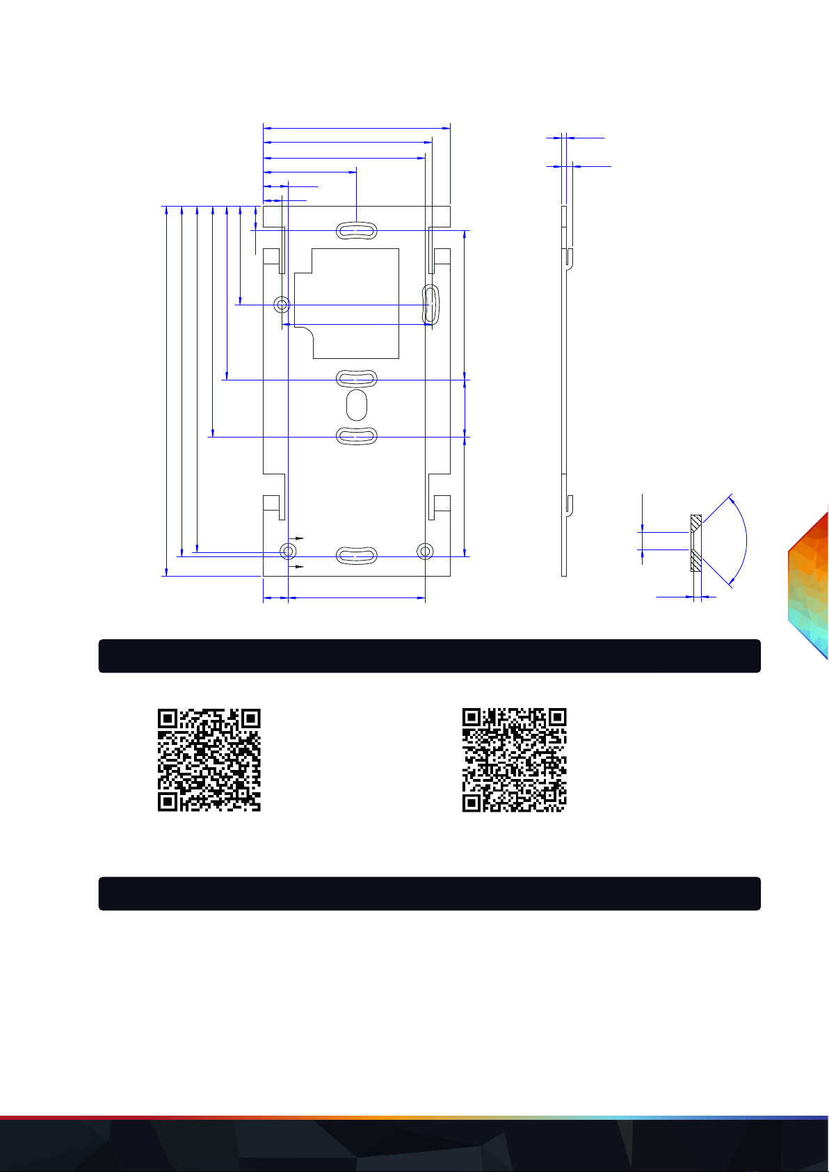
12 Dimensions
All dimensions in mm
Controller 80
160
25.5
4.5
13.5
LIGHTDRIVE+ WiFi — Installation Guide | Certications
content
WWW.TRAXON-ECUE.COM ©2023 traxon technologies. All rights reserved. Installation Guide 02/23 Sheet: 12 / 13
Base plate
A
A
1.49
3.50
2.00
4.50
90.0°
Sectional drawing A-A
(all countersunks)
7.6
10.0
37.5
64.9
67.7
9.6
39.5
69.7
92.7
139.0
140.7
60.0
23.048.0
60.0
10.0 55.0
75.0
148.5
A
A
1.49
3.50
2.00
4.50
90.0°
Sectional drawing A-A
(all countersunks)
7.6
10.0
37.5
64.9
67.7
9.6
39.5
69.7
92.7
139.0
140.7
60.0
23.048.0
60.0
10.0 55.0
75.0
148.5
13 Further guides
Onboarding Guide: Conguration Guide:
Link to PDF Link to PDF
14 Trouble shooting
No function of the device.
Check the power supply and that 12 V DC are available. Check the polarity of the power supply.
Device starts up, but hangs and has no function.
Contact the e:cue support.
LIGHTDRIVE+ WiFi — Installation Guide | Further guides
content

WWW.TRAXON-ECUE.COM ©2023 traxon technologies. All rights reserved. Installation Guide 02/23 Sheet: 13 / 13
Please check for the latest updates and changes on the Traxon website.
© 2022 TRAXON TECHNOLOGIES. ALL RIGHTS RESERVED.
www.traxon-ecue.com
Deviceworks,buttheconnectedxturesdonotreact.
Check correct polarity of the DMX connection. Check the correct assignment of the DMX Zones with the
LIGHTDRIVE+ app.
The Tone button does not work.
Check if using the Tone button is allowed with the DIP switch no. 8 on the backside.
Can I repair the device myself?
No. Do not try to repair the device. Return it to your e:cue distributor for replacement or repair.
15 FAQ
Is it possible to use more than one LIGHTDRIVE+ WiFi?
Yes. You can integrate multiple LIGHTDRIVE+ WiFis in your installation. When you want to synchronize their
activity, use Ethernet cables at the Ethernet connections (C 3 to C 6) and make sure all network settings are
coordinated.
How can I supply power to the LIGHTDRIVE+ WiFi?
You have two options: a) use an external power supply unit at the Power Supply input (connections A 1 and A
2), or b) use PoE at the connections C 1 and C 2.
What is the voltage for powering the LIGHTDRIVE+ WiFi?
The voltage is 12 V DC.
CanIusetheLIGHTDRIVE+WiFitopowerthextures?
No, this is not possible. But you can use one power supply unit for both.
LIGHTDRIVE+ WiFi — Installation Guide | FAQ
content
This manual suits for next models
1
Table of contents
Popular Dj Equipment manuals by other brands

Light O Rama
Light O Rama PixieLink sACN Adapter user manual
Anolis
Anolis ArcSource Outdoor 16 MC Pixel User instructions

American Audio
American Audio DP-2 User guide and reference manual

Kustom
Kustom XII SRM owner's manual

thomann
thomann Stairville DCL Flat Par 18x4W CW/WW user manual

ETC
ETC Irideon FPZ user manual


