ProSpot Fitness PC-1000 User manual

Pno$PoWness
rM
Modet
Pc-tooo
Owners
Manual
1)Assembly
Instructions/Illustrations
2)Use
andOperation
ofPnoSYor/itnessrM
Product
3)Maintenance
ofyour PnoSrory'tzessrM
Product
4)Warranty Information
5)Parts
List
Serial#:
ilililililtililrilililil||il||il
ilillililllililll
34504D00044PC-1000

TableofContents
Assemblylnstructions. ..........1-5
Useand
OperationofYourPROSPOUtnessrM
Product......
.....,..........6-7
Periodic
Maintenance
of
your
PROSPOffrnessrM
Product......................8
WarrantyInformation. .........9
Parts
List.... .....10

lnstructions
for
Assembly
ofthePROSPOTItnessrMPC-1000
. Before
assembly,choosea safelocationforyourPROSPOFJitnessrMPC-1000.ThePROSPOTlrressrMPC-
'1000
has a footprintof approximately6'x 6'. The barbellis approximately7' long. Locateyour
PROSPOTlrressrM
PC-'|000
away
fromanysourceof
water.Donot
allowany
liquid
tobe
near
themachine
orspilledonanyelectrical
part.Donotinsertanyobject
intotheelectrical
box.
. Approximateassemblytimeis1/2
hours.
o Aflatareaof8'x8'willberequiredtoassembleand
properly
usethe
PROSPOTlrtersrM
PC-1000.
. Youwillneedthefollowingtools
anda helpertocompletetheassembly:
. 5mmAllen
Wrench
. 14mmBoxEnd
Wrench
. 17mmBoxEndWrench
. 19mmBoxEnd
Wrench
. FloorPadding,suchascardboard,toavoidscratching
your
floorduringassembly.
. A goodpair
ofscissors
willbehelpfulinseparatingthe
parts
from
oneanotherwhileremovingthemfrom
the
caTtons.
o HANDTIGHTEN
all
bolts.DONOTfullytighten
bolts
until
instructed
todoso.
. Beforeassembly,separate
andidentifytherighfsided
parts
from
the
left-sided
parts.
These
parts
areeasily
distinguishedbythe
mannerinwhich
the
pre-drilled
holesalignwithcorresponding
parts.
orare
identified
by
"L"&"R"stickers.
. ThePROSPO"ffitnessrM
PC-1000usesseveraldifferentlengthsofbolts.Becareful
to usethecorrectlength
ofboltcalledforateachstepofassembly.
Refertothesizingcharts
provided.
r WARNING:Never perform any maintenance
on the PROSPOT/itnesslM
PC-l000whilethePowerSupply
is plugged
intothewall!!!
STEP# 1: MAINFRAMEASSEMBLY
1. PlacethetwoBaseRails
(1& 2) oppositeeachotherinthecenteroftheassembly
areaasshowninthe
lllustration.PlacetheLowerCrossBrace
(3)
betweenthetwoBaseRails
(1
& 2)sothatthe
side
pre-drilled
holesoftheBaseRails
(1
&2)alignwiththeendholesoftheLowerCrossBrace
(3).
2. Carefully
threadtheCrossBraceWireHarness
(8)
throughthecorresponding
side
pre-drilled
holes
ofthe
BaseRails
(1
&2)then
pull
the
WireHarness
(8)
outofthetop
holes
oftheBaseRails
('l&2).
3. AttachthetwoBaseRails
(1& 2)totheLowerCrossBrace
(3)usingtwoUpright
SupportPlates
(6),
four
bolts
(22),
eight
washers
(18)
andfournuts
(20)
asshown.HANDTIGHTENthebolts
atthistime.
4. Attachthe Right
UprightGuidepost
Assembly
(7, 10,23\ to the Lower
CrossBrace
(3)andthe Upright
SupportPlate
(6)
attachedontherightbaserail
(1)
usingtwobolts
(22),
fourwashers
(
18)
andtwonuts
(20)
asshown.
HANDTIGHTEN
theboltsatthistime.
5. Attachthe LeftUprightGuidepostAssembly
(9, 12,23) to the LowerCrossBrace
(3)andthe Upright
SupportPlate
(6)
attachedontheleftbaserail
(2)
usingtwobolts
(22),
fourwashers
(
18)
andtwonuts
(20)
asshown.HANDTIGHTENtheboltsatthistime.
6. Plug
togetherboth
oftheCrossRailWireHarness
(8)
tolowerendsofthe
SpiralSignalCables
(46)
Iocated
just
underthe
perforated
SliderShieldsonback
oftheScreenPanels
(23).
__1__

7. Attach
thetwo
RearSupport
Frames
(4)
tothetwobase
rails
(1
&2)usingfourbolts
(22),
eightwashers
(18)
andfournuts
(20)
asshown.
HANDTIGHTENthe
bolts
at
thistime.
8. Attachthetwo
PulleySupportFrames
(17)
tothe
RearSupportFrames
(4)
andtheUprightGuidePosts
(10
& 12)usingeightbolts
(28),
sixteenwashers
(18)
and
eight
nuts
(20)
asshown.HANDTIGHTEN
thebolts
atthistime.
9. Attach
theUpperCrossBrace
(11)
tothe
twoRearSupport
Frames
(4)
using
fourbolts
(51),
eightwashers
(18)
andfournuts
(20)
asshown.
HANDTIGHTENthebolts
atthistime.
'10.
Tightenallboltsandnutsused
for assembly
in previous
steps.
11.Carefully
insertthe LeftWeightBar
Knuckle
(44)
upthroughtherectangularcutoutinthe PulleySupport
Frame
(17)
andflextheLeft
WeightBarCables
(24)
ontothe
pulleys(27)
sothatthecables
insert
intothe
grooves
of
eachcorresponding
pulleys
andallowing
theLeftWeightBarKnuckle
(44)
tohangfree.Besure
thatthecablesare
straightanduncrossedand
cablesand
pulleys
movesmoothly.
12.Repeatthestep
11
onthe
right
side
ofthePROSPOT/nsssrM
PC-1000.
STEP
#2: SENSOR
WEIGHTBAR
INSTALLATION
1. Standing
infrontofthePROSPOTlrressrM
PC-1000.Insertoneendand
thenthe
other
end
ofthe
Sensor
WeightBar
(25)
intotheKnuckles
(42
& 44).SlidetheknucklesontotheBaruntiltheyrestsnugly
against
thepreinstalled
sensorretainingcollars
(45
&48)at eachendoftheSensorWeightBar
(25).(There
isa
rotationlimi{ing
pinthatprotrudes
fromthebottomoftheSensorWeightBar
(25)
thatmustfitthrough
a slot
intheknuckles
g? A 44tas
itisslid
into
position).
2. PlaceonePlasticLockingSleeve
(39)
onto
eachendoftheSensorWeightBar
(25)
andslidetheminwards
untiltheybuttupagainstandsecure
theWeightBarCable
Knuckle
in
place.
TightenPlasticLockingSleeve
boltssecurely.
3. PlaceoneoftheOlympicAdapters
(30)
ontotheSensor
WeightBar
(25)
andslidethemontotheBaruntil
theytouchthePlasticLockingSleeves
(39).
InsertanOlympicAdapterRetainingPlug
(33)
ontoeachend
oftheSensorWeightBar
(25)
sothattheyalso
go insideof theOlympicAdapters
(30).
Securewithtwo
Allen
bolts
(29),
twowashers
(36)
andtwospring
washers
(56).
4. Attachthefoursmall
plasticpipes(15)
tothetwoPulley
Support
Frames
(17)
using
four
bolts
(34),
eight
washers
(38)
andfournuts
(35)
asshown.
Tightenthe
boltssecurely.
5. Attach
thesixSideWeightPlate
Holders
(14)
tothetwoRearSupportFrames
(4)
using
twelvebolts
(53),
twenty-fourwashers
(18)
andtwelvenuts
(20)
asshown.Tightentheboltssecurely.
6. Carefullythreadthe rear
endsof the CrossBraceWire Harness
(8) throughthe middleholeon the
ElectronicBoxLocating
Plate
(13)
and
thenattachtheLocatingPlate
(13)
to theLower
CrossBrace
(3)
usingtwobolts
(22),
four
washers
(18)
andtwo
nuts
(20).
Tightentheboltssecurely.
7. Attach
theElectronicBoxProtectingCover
(5)
totheLocatingPlate
(13)
usingtwocrossscrews
(52)
and
lwowashers
(57)
asshown.Tightenthescrews
securely.
Note:Inthismanualwhenreferringto Leftand
Right
sideofunit,theleftandright
perspective
arefrom
the
outside,facing
the
frontoftheunit.
--2--

UprightGuidepost
Assembly
Diagram
Left Locklng Stlder
Rlght Locklng Stlder
Bock vlevr
--3--

Assembly
Drawing
ofPROSPOTfitnessrM
PC-1000
2?
*
-4-

PROSP
OTlitnessrM
ModelPC-l000
#22
QTY:74
Bolts&
Bushings
Size
Chart
#29 #34
QTY:2 QTY:4
#35
QTY:4
@
M5
#78
QTY:84
#53
QTY:72
#20
QTY:42
#57
QTY:4
QrY:2 #56 #Bg
QTY:2
,/T\ QTY:8
9ff@ @
#28
QTY:8
=
=
Mt2
#36
8/76 mm M I
72,/24 mm
5/7O mm

!lRead!!
ThisPageBeforeUsing
Your ProSpotJitnessrMProduct
SafeUseof Your ProSpotJitnessrMProduct
1. CAUTION:
Thismachineinvolvestheriskof possible
injury by itsuser.
THE FOLLOWING RULES SHOULD BE CARFULLY FOLLOWED:
1) Consult a physician or other healthcare
provider before beginningan
exercise
program.
2) If you arein badhealthor arehandicapped,askfor the opinionof your
physician
andexerciseonlyunder
qualified
supervision.
3) Discontinueto exerciseif you experienceany light-headedness,dizziness
or shortnessof breath
andconsult
yourphysician.
2. l) Keep smallchildrenandothersat a safe
distancefrom all movingparts.
Theupand
downmovementof theweightscanbedangerous.
2) Neverallow your fingers,toes,
hair,otherbodyparts
or looseclothingto
comenearweightswhiletheyarein motion.
3) Neverattemptto exercise
with moreweightthan
youare
physically
able
to
handle.
4) Periodicallyinspect
your machineto ensureall parts
arefreefrom defect
andarefully operational.
5) Checkall fastenersto makesure
nonehave
loosenedwith use.Tighten
any
loosefastenersif necessary.
3. Warning: Never
performany
maintenanceontheunitwhilethe
power
supply
isplugged
intothewall.
--6--

2.
3.
5.
4.
1.
7.
11.
Donotallowanyliquidto be nearthemachineor spilledonanyelectrical
part.
Donotinsert
any
foreign
object
intotheelectricalboxorattempttoopen
it.
lfyou
haveany
questions
orneed
helprefertoourwebsiteatwww.prospotfitness.com.
Connectthepower
supplytoastandard
'110
volt
grounded
receptacle.
ltisrecommendedthatsurge
protection
is
usedto help
protect
andextendthelifeoftheElectronic
Boxoftheunitfrom
power
surgesandlightingstrikes.A
flashing
green
IightwillappearontheElectronicBoxwhen
power
ison.
AfterassemblyofyourPC-1000
becomefamiliarwiththeGrab
andGo@systembelore
placing
weights
onthe
barbell.
Assumea normalstarting
position
for
your
desired
freeweightexercise.
RotatethebarbellsothattheTouchSensorStripembedded
in
thebarbellistouching
your
fingertips.
ltishiqhlv
recommended
that
when
gripping
the
barbellthat
you
useathumbover
grip.
This
will
prevent
theBarbellsensor
fromcontactwith
the
your
thumbs
whenlockingisdesired.Itisnecessary
tomaintain
skincontactwith
thetouch
sensorstripthroughout
your
freeweightexercise.Once
you
have
grasped
theTouchSensor
Strip,
you
willheara
soft'click'andasolidredlightwillappearontheElectronicBoxinadditionto
theflashing
greenpower
light.
Whilestill
grasping
thebarbell,evenlyliftit upwarda minimumof %"
on bothsidesof thebarbell.Thisupward
movement
willdisengagethelockingmechanism.
lf youhave
performed
thisstepcorrectly,
thebarbellwillnow
beunder
your
control,thecableswillmovefreelyoverthe
pulleys
andtheSlider
Knuckleswillslidesmoothly
up
anddowntheGuidePosts.Youcannowsafely
perform
any
free
weightexercisewithout
theneedofa spotter.
SimplyGrab&Go@!
Lockinq
ofthe
Barbell:
Whilemaintaininga controlled
grip
ofthebarbell,remove
your
fingertips
fromtheTouch
SensorStriponeitherhand
(make
surenoothercontactisbeingmadewithTouch
Sensor)andslowlylower
toa
locking
position.
Thereisalocking
position
every1".Nowrelease
yourgrip
completely.
Barbellisnowlocked
and
readyfor
theyournext
movement.
Alwaysmaintaincontrolofmovementofthebarbell.Donotallowbarbell
toswingagainst
machineframe,asthis
maycausedamage
tothe
finish.Donot
attempttothroworslamthebarbellattachedtothecables,asthismay
resultindamage
tothe
locking
mechanism.
lntentional
misuseofthePC-1000willvoid
anyandallwarrantres.
Once
you
are
familiar
withtheGrab&Go@system,
position
barbellintheproper
starting
position
for
your
desired
exerose,
Makecertainthe barbellis levelbeforeloadingweight
plates.
Level
the barbellby raisingup one endof the
barbelluntillevel.
(ThePC-1000is designedwitha ratchetingfeature
thatallowsit to bemanuallyraisedfrom
sidetoside.)
Or,
level
thebarbellby
grasping
itwithbothhands,making
surethefingertipsmake
contactwiththe
touchsensor
strip.
Lift
onbothsidesthebarbellupwarda minimumof%'to release
thelockingmechanism
and
adjust
barbelluntillevel.Oncethe barbellis level,release
yourgrip
ontheTouchSensor
Stripto engagethe
lockingmechanism.
Loadweightsevenlyonbothsidesofthebarbell.
Secureallweight
plates
withaspringcliporlockingcollar.Youarenow
readytobegin
your
free
weightexercise
routine.
Never
attemptto liftmoreweightsthan
you
can
safely
handle.Never
put
morethan750
pounds
ontheBarbell.
Beforeremovingweight
plates
fromweighted
barbell,
make
surethebarbellisina level
position.
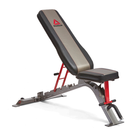
PCB-F10Bench
(FlavDecline):
Thisbenchhasonlytwo
positions,
flatand
decline.Toadjust
bench,
grab
handle
withonehand
andthe otherontheLegholddownsupportrail.
Liftandslidebenchmechanism
to itsfurthest
adjustmentforflatordecline
position.
Donotusean in-betweensefting,
thiscouldcreatea dangeroussituation
andcouldcauseinjury
touser.
PCB-M10Bench
(Military/lncline):
Thisbenchhasonlytwo
positions,
military
andincline.To
adjustbench,
grab
handle
withonehand
andtheotheronthebottomofthebenchseat.Liftmostlywith
thehandle,with
a slightlift
onbenchseatandmovebenchmechanism
toitsmaximum
adjustmentformilitaryorincline
position.
Donot
use
anin-betweensetting,this
couldcreateadangeroussituatjonandcouldcauseinjury
touser.
Never
put
your
handsinthebenchslidingor
pivoting
mechanisms,this
couldcauseinjury.
8.
9.
10.
12.
't4.
15.
16.
17.
--7 --

Maintenance
ofProSpotJitnessru
Product
Intro: Our products
are madeof durablematerialsand havebeenfactory testedto assur'e
proper
function and reliability. Along with our EquipmentWarranty,this givesthe owner of our
producttheconfidenceof a longlasting
relationshipwith ProSpoftnesst* lnc.Oursystemsare
designed
in awayto allow easy
replacementofparts bothmechanicalandelectricalif theneed
should
everarise.If you areanewowner
of a ProSpolftuessnsystem,three
important
things
needto bedone
to assure
prompt
serviceunder
thewarranty:
I. Fill outand
fax or mailto usyourProductWarranty
RegistrationCardalongwith acopyof
your salesreceipt
(proof of purchase)if this hasnot beendoneby your dealerat time of
purcnase.
2. Yoursystemneeds
to besetupproperly
accordingto theassembly
manual.
3. Followuserinstructions
onhowto properly
usethesystem.
Maintenance
Program
Note: Our productsare recommended
for climate controlled environments.Outdoor use is not
recommended
andwill voidthe
warranty.
Carefully
inspectmachine
beforeeachuse
to determinethatit isfreefromdefects.
DoNOT use
machineif youfind:
I. A loose,broken
or frayedcable
- (needs
to bereplaced)
2. A loose,brokenor frayed
power
cord
- (needs
to bereplaced)
3. Any broken,cracked,torn, frayed or defectivepart of the machine
- (needs
to be
replaced)
4. Checkall fastenersto make surenone have loosenedwith use.Tighten any loose
fasteners.
5. Checklorfreemovementofall cable
pulleys.
Adjustifnecessary.
6. Make sureguide rods and upright guide postsare free of dirt, adhesiveresidueor
moisture.Standard
siliconelubricant
(purchased
from fitnessdealers)is recommended
forthe
lubricationofthese
Darts.
Warnine: Never perform any maintenanceon the unit while the power
supply
isplugged
intothewall.
--8--

Warrantv Information
EachPnoSrorf/zessn
Product
comes
witha limited
parls
replacement
wananty.
Pleasereferto the
actual
warranty
cardincluded
withyour
system
forspecific
coverage.If you
haveany
questionsabout
performance
underthis
limited
waranty,
please
write
usat:
PnoSrorlrze.ss,
Inc.
Attn: WarrantyService
1325
Oakbrook
Drive,SuiteE
Norcross,
GA30093
Office
(770)446-9299
Fax (770\-446-7213
--9--

PROSPOTfirness
rM
Model
PC-1000Parts
List
4 RearSupport
Frame 2
Assy#
I Description
1 RightBaseRail
2 LeftBaseRail
3 LowerCrossBrace
5 ElectronicBoxProtectingCover
6 UplghtSupport
Plate
7 RightLo.ckingSlider
9 LeftLocl
ing
Slider
10 Right
UprightGuide
Post
12 LeftUprightGuide
Post
19 ; Electronic
qox
Lgcating
Plate
14 Side
WeightPlateHolder
8 - CrossBraceWire
Harness 2
,QtY
1
l1
.12
1
11 |InnPrCrnssBrace 1
1
1
1
1
6
1
6 PlasticlnnerSleeve
50/90mm 4
17 PulleySupport
Frame 2
I
18 _ Flat
Washer12ll.a1q 8!
1s 9pqqlg
Disc 8
20 Nylon-lockNut
!il! , 42
21 Rr.rbberBumper
Ring45172mm 6
22 HexHeadBoltN412x120
mm 14
23 Screen
Panel
21 welslrtBqCablq,leJt , 2
25 SensorWeight
Bar r1
26 HexHeadBoltM12
x 160mm . 4
27 B!9
f qlley,
dpqQle-groqile : 4
28 : HexHead
BoltM12x125mm 8
29 AllenBoltM8x40mm 2
t2
32
33
34
31 Spring
Clip,50
mmDia
RubberBumper
Ring50/80mm
- OlympicAdapterRetaining
Plug | 2
HexHeadBoltM5
x60mm 4
35 Nylon-lockNut
M5 _ I
36 Fl?twasher
8/1q
nryl _ 2
37 Roundlnnel.Plug,
45mmDia, , 6_
38 FIatWasher
5i10Jnm I
39 PlasticLockingSleeve ', ?
40 Solenoid
41 _ FootEndCap90x
50
mm ' 4
42 light WeightBar
Kluckle - _1
43 _ RlghtSliderKruckle 1
44 LeftWeightBar
Knuckle 1
45 : SqnsorRetaining
Collar,
right , I
46 i i;; c"bte l -?
- t-
47 lVeight
BarCable,.right 2
19 . 9glsqt
Rglqqnlfs_ca[qr,
left
__ , 1_-
49 Slider
KnuckleRetaining
Pin 2
t--
50 ' qottqr
Pin - )-Z
-.xHead
BoltM12
x 115mm : 4
51 HexHead
Boltl\412
x 115mm
!? _ clgssSc1ery
\!{x!0 mm
53 : _fqxlleadBglt
M12x70mm
2
12
2
1
2
2
58 t Block,#SB-90 2

HOWTOUSESPOT
BLOCKS
UsingSpotBlocks
is
quick
and
easy.Just
followtheseinstructions:
ToUseSpotBlocksasaSecondarv
LockinqDevice
1. Before
positioning
Spot
Blocks,
place
thebarbellintothelowest
position
fortheexercise
you
willbe
performing.
2. Once
barbellis
placed
in
desired
position,
lower
Spot
Blockssothat
they
are
touchingthetopoftheslider
lockingblock
(the
black
boxwiththe
ProspotFitness@logoon
it).TomoveSpotBlocks,
placeyour
indexand
middlefingersunderneath
thefinger
grip
and
your
thumbon
the
push-
releaselever.Push
inthe
push-release
leverwith
your
thumband
move
intodesired
position.
Releasethe
push-release
levertolock
the
Spot
lock
in
place,
thenensuretheyare
securely
lockedbeforeusingbarbell.
3. Once
in
place,
thebarbellcannot
beloweredbeyond
the
position
ofthe
Soot
Blocks.
ToUseSpot
Blocks
asaTraining
Aid
1. Determinewhere
your'stickingpoint'
isfordesiredexercise.
(The
'sticking
point'
referstothespecific
portion
of
themovementwhere
you
are
the
weakestandstruggletomovethebarbell
upwardanyfurther.)
2. PositiontheSpotBlocksat
thebeginning
of
your'sticking
point'.(Refer
to
f2 aboveonhowtomoveSpotBlocks.)
3. Performthedesiredexercise
withSpot
Blocksin
place.
You
willnotbe
able
tolowerthebarbelow
your'sticking
point',
causing
your
muscles
to
workharderatthis
point.
Using
thistechnique
willstrengthen
thisareaand
helptoeliminate
your'sticking
point'.
ALWAYSUSESPOT
BLOCKS

ProSpot,
Inc.EquipmentLimitedWarranty
The ProSpot Pxxx (In Home)SeriesandEe11g (Commercial) Seriesof Systemscomewith a limited
parts warranty. This warranty doesnot covermisuse,neglector abuse
of the product, or damage
dueto an 'A.ct of Nature", weather,theft, improper installation and vandalism. All time periods are
from the dateof purchase. Parts are warranted to befree from defectsin materials and
craftsmanship for the duration of the warranty period stated,
DURING TIIE WARRANTY PERIOD FOR EACH WARRANTY DESCRIBED BELOW,
PROSPOTPROMISES TO PROMPTLY REPLACE OR REPAIR ANY DEFECTIVE PART.
TIIERE ARD NO OTIIER EXPRESSEDOR IMPLIED WARRANTIES ON PROSPOT
PRODUCTS.
TO THE EXTENT ALLOWED BY LAW:
r. IF THIS ISA CONSUMERTRANSACTION.ANY IMPLIED WARRANTY OF
MERCIIANTABILITY OF FITNDSS IS LIMITED TO TIIE DURATION OF THIS WRITTEN
LIMITED WARRANTY. IF THIS IS A COMMERCIAL TRANSACTION, ALL IMPLIED
WARRANTIES ONCLI,'DING WITHOUT LIMITATION THE IMPLIED WARRANTIDS OT'
MERCHANTABILITY AND FITNESSFORPURPOSE)
AR-ESPECIFICALLY EXCLUDED.
2. PROSPOT
SIIALL NOT BE LIABLE FORANY DAMAGES,INCLUDING ANY
INCIDENTAL, INDIRS,CT, SPECIAL OR CONSEQUENTIAL DAMAGES RESULTING FROM
TIIE USE OR CONDITION OF THE PROSPOTPRODUCT. THE CONSTJMERSSOLE AND
EXCLUSIYE REMEDMS FOR LIABILITY OF AI.IY KIND (INCLUDING WITHOUT
LIMITATION, DIRECT OR GENERAL DAMAGES) WITH RESPECT TO TIIE PROSPOT
PRODUCT SHALL BE LIMITED TO THE REMEDY PROVIDED IN TIIIS WARRANTY OR AT
THE SOLE OPTION OF PROSPOT,A REFUI\D OF TIIE PI,'RCHASE PRICE PAID.
SOMESTATESDO NOT ALLOW LIMITATIONS ONHOW LONG AN IMPLIED
WARRANTY LASTSORTHE EXCLUSION ORLIMITATION OFINCIDENTAL OR
CONSEQUENTIALDAMAGES,SOTIID ABOVE LIMITATION OR EXCLUSIONSMAY
NOTAPPLYTOYOU,
This warranty givesyou specificlegalrights, which rnayvary from stateto state. This warranty
is limited to the original owner and is nontransferable. To obtain performance of the warranty
obligation
youmayeithercallProSpot,lnc, at770-446-9299or youmaymail your request
to:
Prospot,Inc,
1325Oakbrook Drive. SuiteE
Norcross,
GA 30093
Nor€tum of equipmentor part will beacceptedby Prospot without awritten return goods
authorization number, All warranties include freight and labor for lirst year only. OWNER
MUST CONTACT PROSPOT,INC. FIRST FORANY SERVICEUNDERTHIS WARRANTY.
All freight charges
andlabor chargesare the responsibility of the owner after lirst year. Returns
shippedfreight-collect will not beaccepted.
In Home (original owner only) Commercial (original owner only)
Frame/cables/ Lifetime Lifetime
Touch sensor
Moving parts/ Lifetime Lifetime
Electrical
Pads 2years I year
Rev
(Jan-04)

Spot
BlockPosition
NumberDecal
ApplicationInstructions
I.Cleanfrontfaceof UprightGuide
Post.
2.Raise
WeightBartohighest
position.
3.PositionSpotBlock
at
top
position.
4.Remove
backinsondecal
to exDoseadhesive.
5.Apply decalstartingatthebottomedge
of SpotBockin thecenterof thepost.
6.Removetoplayerof decaland
smooth
out.Avoid makingcreases.
7.Repeatforotherside.
8.Usenumbersondecal
to position
SpotBlocksatsameandcorrectheight
for eachexerciseto be
performed.
(sB
7-e-04)
Table of contents
Other ProSpot Fitness Fitness Equipment manuals
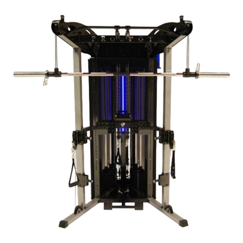
ProSpot Fitness
ProSpot Fitness FUSION HG-5 User manual
ProSpot Fitness
ProSpot Fitness HG-1 User manual

ProSpot Fitness
ProSpot Fitness P-50 User manual
ProSpot Fitness
ProSpot Fitness P-100 User manual
ProSpot Fitness
ProSpot Fitness P-600 User manual
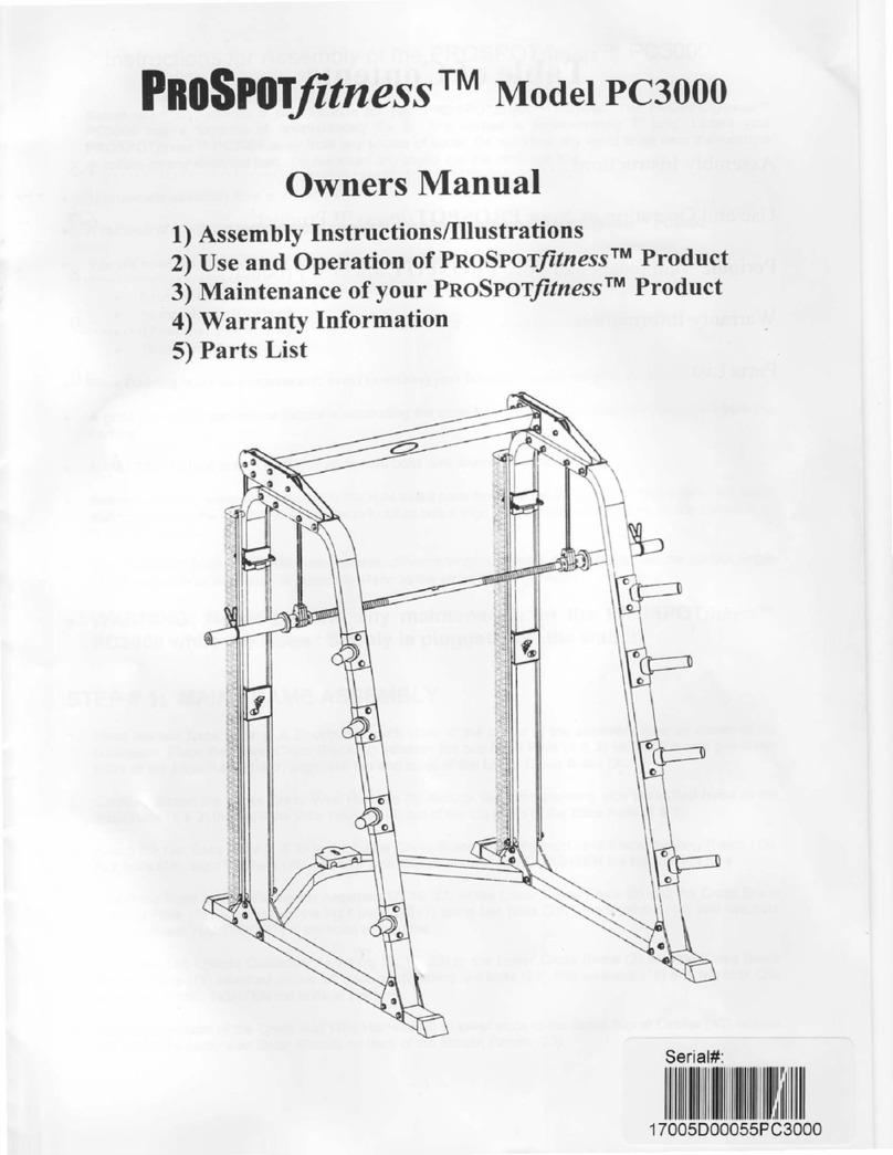
ProSpot Fitness
ProSpot Fitness PC3OOO User manual
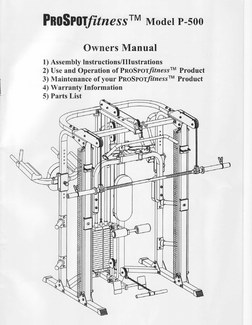
ProSpot Fitness
ProSpot Fitness P-500 User manual
