ProSpot Fitness P-100 User manual

Pno$p
olfitness
rM
Moder
P-roo
Owners
Manual
1)AssemblyInstructions/Illustrations
2)UseandOperationofPnoSnory'lzessrM
Product
3)Maintenance
ofyour PnoSrofirzessrM
Product
4)Warranty Information
5)PartsList

Table
ofContents
AssemblyInstructions. .............1-5
UseandOperationofYour
PROSPOffrnessrMProduct..............
........6-7
Periodic
Maintenanceof
yourPROSPOTttnessrM
Product.....................8
WarrantyInformation. .........9
Partslist.... ............10

lnstructions
forAssembly
ofthe
PROSPOTy'tnessrMP-100
Beforeassembly,
chooseasafe
locationfor
your
PROSPOffttuessrMP-100.
ThePROSPOTlrzessrMP-100
hasafootprintofapproximately6'x
6'.Thebarbell
isapproximately
7'long.Locate
your
PROSPOTltrressrM
P-100
awayfromanysource
of water.
Donotallowanyliquid
lo be near
themachine
or spilledon any
electrical
part.Donotinsertanyobject
intotheelectrical
box.
Approximateassembly
time
is1/2hours.
A flatareaof8'x 8'willbe
requiredtoassembleand
properly
usethePROSPOTIT/gssIMP-100.
Youwillneedthefollowing
toolsanda helpertocomplete
theassembly:
. 5 mm
AllenWrench
r 14mmBoxEndWrench
o 17mmBox
EndWrench
. 19mmBoxEndWrench
FloorPadding,suchascardboard,toavoidscratching
your
floorduringassembly.
A good
pair
ofscissorswillbehelpful
jn
separating
the
parts
fromone
another
whileremoving
themfromthe
cartons.
HANDTIGHTENallbolts.
DO
NOTfullytighten
boltsuntilinstructedto
do
so.
Beforeassembly,separate
andidentifythe rightsidedparts
fromthe left-sided
parts.
These
parts
areeasily
distinguishedbythemanner
inwhich
the
pre-drilled
holesalignwithcorresponding
parts,
orare
identified
by
"L"&"R"stickers.
ThePROSPOTlrressrMP-100usesseveraldifferentlengthsof bolts.Becarefulto usethecorrectlengthof
boltcalled
forateachstepof assembly.
Refertothesizingcharts
provided.
. WARNfNG:Never
perform
anymaintenanceonthePROSPOTfitnessrM
P-
100whilethePowerSupplyisplugged
intothewall!!!
STEP#1: MAINFRAMEASSEMBLY
1. Place
thetwoBase
Rails
(1& 2) opposite
eachotherinthecenter
oftheassemblyareaas showninthe
lllustration.Place
the
LowerCrossBrace
(3)
betweenthetwoBaseRails
(1
& 2)sothattheside
pre-drilled
holes
of
theBaseRails
('1,
2)alignwiththeendholesoftheLower
Cross
Brace
(3).
CarefullythreadtheBaseRailWireHarness
(8)
throughthecorrespondingbig
end
holes
ofthe
Lower
Cross
Brace
(3)
then
pull
theWireHarness
(8)
outofthebackbigholesoftheLowerCrossBrace
(3).
AttachthetwoBaseRails
(1
& 2)totheLowerCrossBrace
(3)
using
twoCross
BraceBacking
Plates
(13),
fourbolts
(28),
eightwashers
(18)
andfournuts
(20)
asshown.HANDTIGHTENthe
boltsatthistime.
AttachtheRight
Upright
GuidepostAssembly
(7,
10,53)andthe
twoUprightSupportPlates
(6)
totheRight
BaseRail
(1)usingfourbolts
(28),
eight
washers
(18)
and
four
nuts
(20)
asshown.HANDTIGHTEN
the
boltsatthistime.
(Note:
Thelong endof the UprightSupportPlate
(6)
should point
to the rear
of the
machine
asshowninthe illustration).
AttachtheLeftUprightGuidepostAssembly
(9,12,53)andthetwo Upright
Support
Plates
(6)
totheLeft
Base
Rail
(2)using
four
bolts
(28),
eight
washers
(18)
andfournuts
(20)
asshown.HANDTIGHTENthe
boltsat
thistime.
(Note:
Thelongendof the UprightSupportPlate
(6)
should point
to the rearof the
machineasshownintheillustrationl.
2.
3.
5.
I

o_
7.
9.
L
Plugtogetherboth
oftheBaseRail
WireHarness
(8)
tolower
endsofthe
Spiral
SignalCables
(46)
located
just
under
the
perforated
SliderShields
onbackoftheScreen
Panels
(53).
AttachthetwoRearSupport
Rails
(4)
totheLower
CrossBrace
(3)
andtheCrossBraceBackingPlates
(13)
usingfourbolts
(28),
eightwashers
(18)
andfournuts
(20)
asshown.HAND
TIGHTEN
theboltsatthistime.
Attachthe
twoBigPulleys
(27)
tothe
twoUpper
LinkingPlates
(17)
using
twobolts
(19),
four
washers
(23)
andtwo
nuts
(26)
asshown.
HANDTIGHTENtheboltsatthistime.
LifttheUpperLinking
PlatesAssembly
(17
&271
and
place
itontopoftheLeftUprightGuidepostAssembly
(9,
12,53),andattachthetwo
UpperLinkingPlates
(17)
totheLeftUprightGuidePost
(12)
using
twobolts
(22),
fourwashers
(18)
andtwo
nuts
(20)
asshown.HAND
TIGHTEN
theboltsatthistime.
'10.
Carefully
flextheLeftWeightBarCables
(24)
ontothe
pulleys
(27)
sothatthecablesinsertintothe
grooves
ofeachcorresponding
pulleys
andallowingthe
LeftWeightBarKnuckle
(44)
tohangfree.
Besurethatthe
cablesarestraightanduncrossedandcables
and
pulleys
movesmoothly.
11.AligntheholesontopoftheRearSupportRail
(4)
withthecorrespondingholesonthe
twoUpperLinking
Plates
('17)
andattachtheRearSupport
Rail
(4)
totheLinkingPlates
(17)
usingtwo
bolts
(22),
four
washers
(18)
andtwonuts
(20)
asshown.
HANDTIGHTENtheboltsatthistime.
12.Repeatthesteps8
- 11
onthe
right
sideofthe
PROSPOTT/rressrMP-'l00.
13.AttachtheUpperCross
Brace
(11)to
thefourUpperlinkingPlates
(17)
usingfourbolts
(22),
eightwashers
(18)
andfournuts
(20)
asshown.HAND
TIGHTENtheboltsat
this
time.
14.
Tightenallboltsand
nutsusedfor assembly
in previous
steps.
STEP
#2: SENSORWEIGHTBARINSTALLATION
1. Standinginfront
of thePROSPOTlaessrMP-100.Insertoneend
andthentheotherendof theSensor
WeightBar
(25)
intotheKnuckles
(42
& 44).
Slide
theknuckles
ontotheBar
untrlthey
rest
snuglyagainst
the
preinstalled
sensorretainingcollars
(45
&48)at eachendoftheSensorWeightBar
(25).(There
isa
rotationlimiting
pin
that
protrudes
fromthebottomoftheSensorWeightBar
(25)
that
must
fitthroughaslot
intheknuckles
U2 & 44\
as
itisslidinto
position).
2. Place
one
Plastic
LockingSleeve
(39)
ontoeachendoftheSensorWeightBar
(25)
andslidetheminwards
untiltheybuttup
againstandsecurethe
WeightBar
Cable
Knuckle
in
place.
TightenPlasticLocking
Sleeve
boltssecurely.
3. Place
oneoftheOlympicAdapters
(30)
ontotheSensor
Weight
Bar
(25)
andslidethem
ontotheBaruntil
theytouchthePlasticLockingSleeves
(39).
lnsertanOlympicAdapterRetaining
Plug
(33)
onto
eachend
oftheSensorWeightBar
(25)
sothattheyalso
go insideoftheOlympicAdapters
(30).
Securewith
two
Allenbolts
(29)
andtwowashers
(36).
4. Attachthefoursmall
plasticpipes(15)
to thefourUpperlinkingPlates
(17)
using
fourbolts
(34),
eight
washers
(38)
andfournuts
(35)
asshown.Tightentheboltssecurely.
5. Attach the ElectronicBox LocatingBoard (40) to the LowerCross Brace (3) usingtwo bolts (22), tour
washers
(18)
and
two
nuts
(20)
asshown.Tightentheboltssecurely.
6. Attachthesix
Side
Weight
PlateHolders
(14)
totheRear
Support
Rails
(4)
usingsix
backing
plates(16),
twelve
bolts
(22),
twenty-fourwashers
(18)
andtwelvenuts
(20)
asshown.Tighten
theboltssecurely.
Note:Inthismanualwhen
referringtoLeftandRightsideofunit,
theleftandright
perspective
arefromtheoutside,
facingthefrontoftheunit.
--2--

Upright
GuidepostAssemblyDiagram
Leat Lockihg Slide.
Right Locking Stide.
--3--

Assembly
Drawing
ofPROSPOTfirnessrM
P-100
--4--

PROSPOTJitnessrM
ModelP-1
00
#r
lil=l
mul
u.r
_l r!t8 l._
#36
QTY:2
@
8/76 mm
#26
QTY:4 @@
7O/2O
mm Mt2
Bolts
&
Bushings
SizeChart
#29
QTY;2 #79
QTY:4
#38
QTY:8
#22
QTY:26
#23
QTY:8 #20
QTY:46
#28
QTY:76 #34
QTY:4
#78
QTY:92
#52
QTY:4
#35
QTY:4
@
M5
5/7O mm
72/24 mm

l.
!!Read!!
ThisPageBeforeUsingYour ProSpotJitne^s^s
rM
Product
SafeUseof Your ProSpotJitnessrM
Product
CAUTTON:
Thismachineinvolves
the
risk of possible
injury by itsuser.
THE FOLLOWING RULES SHOULD BE CARFULLY FOLLOWED:
Consultaphysician
orotherhealthcare
provider
before
beginninganexercise
program.
Ifyou areinbadhealthorarehandicapped,askfortheopinionofyour physician
and
exerciseonlyunder
qualified
supervision.
Discontinueto exerciseif youexperience
anylight-headedness,
dizziness
or shortness
of breathandconsult
yourphysician.
Keepsmallchildren
andothersatasafedistancefromall movingparts.Theupand
downmovementof theweightscan
be
dangerous.
Neverallowyourfingers,
toes,
hair,other
bodyparts
or loose
clothingto comenearweightswhiletheyarein motion.
Neverattemptto exercise
with more
weight
than
youare
physically
ableto handle.
Periodicallyinspectyourmachine
to ensureall parts
arefreefromdefectand
arefully
operational.
Checkall fasteners
to makesurenonehaveloosened
with use. Tighten
anyloosefastenersif necessary.
J. Warning: Neverperform
anymaintenanceonthe
unitwhilethe
power
supplyis
plugged
intothewall.
2.
--6--

Do not allow any liquid to be nearthe machine
or spilledon any electrical
part.Do not insertany
foreignobjectintotheelectricalboxor attempt
to open
it. If youhaveany
questionsor needhelp
refer
toour
websiteat: www.prospotfitness.com.
1. Connectthepower
supply
to a standard
110-volt
householdcurrent.
While connecting
the
powersupplydonottouchthebarbell
asthismayinterfere
with thecomputer's
initial settings.
If you needto resetthe computer,
simply unplug the power supply,wait 10 seconds
and
reconnect
it. It isrecommended
thatsurge
protectionis usedto help
protect
and
extendthelife
of theElectronic
Box of theunit from powersurges
andlightening
strikes.
A flashing
green
light
will appearonthe
Electronic
Boxwhen
power
ison.
Become
familiar with the Grab and Go@operation BEFORE placing weightson the barbell.
2. PositiontheSpot
Blocks:
Before
positioningthe
SpotBlocks,
placethebarbell
into
thelowest
position
for theexercise
youwill beperforming.Movethebarbellby grasping
it andraising
it
1"to unlock.While grasping
thebarbell
raiseor lowerit intothedesired
position.
Open
hands
to lock the barbellin place.To movethe SpotBlocks,placeyour indexandmiddlefingers
undemeaththefingergrip and
yourthumb
onthepush-release
lever. Pushin thepush-release
Ieverwith yourthumband
movetheSpot
Blockssothat
theyaretouching
thetopof theslider
locking
block(the
black
blockwith theProSpot
FitnessrMlogoonit). Releasethepush-release
levertolocktheSpot
Block
inplace.
3. Assumeanormal
starting
positionfor yourdesired
free-weightexercise.
4. Graspthe
barbell:
I. RotatethebarbellsothattheTouchSensorStripembedded
in thebarbell
is touching
your fingertips. It is necessary
for your fingertipsto maintain
skin contact
with the
TouchSensor
Stripthroughout
yourfree-weight
exercise.
Il. Leam the Rule Of Thumb: Sometimes
referredto asa "false grip" or "sissygrip",
ProSpot's
RuleOf Thumbis a styleof grip in which thethumbdoes
not wraparound
thebarbutrests
alongside
theindex
fingers.Usingthistypeof grip with yourProSpot
FitnessrM
equipment
will prevent
your thumbfrom maintaining
skin contactwith the
TouchSensor
Stripwhen
youattempt
to lockthebarinplace.
IIL Once
you
have
grasped
thebarbell,
you
will hearasoft
'click'and
asolidred
lightwill
appe.uontheElectronic
Boxin additionto theflashing
green
power
light.
5. While still grasping
thebarbell,
lift about1",usinganevenupward
lifting motiononbothsides
of the barbell.This upwardmovement
will disengage
the locking mechanism.
If you have
performedthisstepcorrectly,
thebarbell
will nowbeunder
yourcontrol,
thecables
will move
freelyover
the
pulleys
and
theslider
knuckles
will slidesmoothly
upand
downthe
guideposts.
You cannow safelyperformany free-weight
exercise
without the needof a spotter.
Simply
Grab
and
Go@!
6. Lockingthebarbell
in place:Whenyouare
finishedwith using
thebarbell,
open
yourhandsto
remove
yourfingertips
from the
TouchSensor
Stripatthesamecontinue
to support
thebarbell
with yourpalms.
(Makesure
noother
skincontactis being
made
with theTouchSensorStrip.)
Slowlylowerthe
barbelluntil
it locks
into
position.
There
isalocking
position
every
1".
Now
--7 --

removeyour palms from the barbell.The barbell is now locked and readyfor your next
exerclse.
7. Always maintaincontrolof the movementof the barbell.Do not allow thebarbellto swing
againstthemachineframe,asthismaycausedamageto thefinish.Do notattemptto throwor
slamthebarbellattachedto thecables,
asthismayresultin damageto thelocking
mechanism.
Intentionalmisuseof theP-100will voidanyandall warranties.
Once
familiar with the Grab anil Go@
operation, lou can now begin using the barbell with weight
plates.
8. PositionSpotBlocks
for thedesiredexercise.
(Refer
to#2 above.)
9. Makecertainthebarbell
is levelbefore
loadingweightplates.
Levelthebarbell
by raisingup
oneendof thebarbelluntil it is level.(TheP-100
is equippedwith a ratcheting
featurethat
allowsthebarbellto bemanually
raisedfrom side+o-side.)Or, levelthebarbellby graspingit
with bothhands,
making
surethefingertips
makecontactwith thetouchsensorstrip.Lift the
barbellupwardabout l" to release
it from the locking mechanismand placeit in a level
position.
Oncethebarbell
is level,open
yourhands
to lock it in place.
Loadweightsevenlyon
bothsidesof thebarbell.
10. Secureall weight
plates
with aspring
clip or lockingcollar.You arenow readyto begin
your
free-weightexerciseroutine.
11. Perform
yourexercise
following thestepsoutlined
in#2-6above.
12. Beforeremovingtheweight
plates
fromthebarbell,makesure
it isin alevelposition.
13. Never attemptto lift more weightsthan you can safelyhandle.Never put more than 500
ooundsonthebarbell.
Instructions for using optional high/low pull (PHL-20 or PtilS-200) and weight bench
l. Whenperforming
thehigMow pulleyexercises,add
resistanceby eitherloading
weightplates
ontotheweight
plate
holder
(PHL-20)orusetheweightselector
pin to selectamountof weight
desired
onthe
weight
stack
(PWS-200).
2. Clip desired
attachmenthandletoeitherthe
highor low pulleyclip.
To perform
cableexerciseson thebench,attach
thebench
cableto thelow pulley.
Makesurethe
cable
istautby pullingoutthebenchuntilthereisnomoreslackin thecable
--8--

Maintenance
of ProSpoty'fzessrM
Product
Intro: Ourproducts
aremadeofdurablematerials
andhavebeen
factorytested
to assure
proper
function
andreliability.Along
with
our
Equipment
Warranty,this
gives
the
ownerofour
product
the
confidence
of alonglastingrelationshipwith ProSpot/nessrM
Inc. Oursystems
aredesigned
ina
wayto allow easyreplacement
ofpartsbothmechanical
andelecttical
if theneed
should
everarise.
Ifyou areanewowner
ofa ProSpoflnessrM
system,three
important
thingsneed
to be
doneto
assure
prompt
service
underthe
warranty:
l. Filloutandfax
ormailtous
your
Product
WarrantyRegistration
Cardalongwith
a
copyof
your
salesreceipt
(proof
ofpurchase)
ifthishas
notbeen
doneby
your
dealer
attimeol
purchase.
2. Your
systemneeds
tobesetup
properly
according
tothe
assemblymanual.
3. Followuserinstructions
onhow
toproperly
usethe
system.
Maintenance
Program
Note: Our
products
arerecommendedfor
climatecontrolled
environments.
Outdoor
useis
not
recommended
and
will voidthewarranty.
Carefullyinspect
machinebeforeeach
usetodetermine
thatit is
freefromdefects.
DoNOT usemachineif you
find:
l. A loose,broken
orfrayed
cable (needs
tobe
replaced)
2. A loose,
brokenor frayedpower
cord
- (needs
to bereplaced)
3. Any broken,
cracked,
torn,
frayed
ordefective
parlofthe machine
- (needs
to bereplaced)
4. checkall fasteners
to makesurenonehave
loosenedwith use.Tighten
anyloose
fasteners.
5. Checkfor
freemovement
ofall cable
pulleys.
Adjustifnecessary.
6. Make
sure
guide
rods
andupright
guideposts
arefree
of dirt,adhesive
residue
ormoisture.
Standardsilicone
lubricant
(purchased
fromfitnessdealers)
is
recommended
forthe
lubrication
ofthese
oarts.
Warning: Neverperform
anymaintenance
ontheunit while the
power
supply
is
plugged
intothewall.
--9--

Warrantv Information
EachPnoSeof/nessrM Productcomeswith a limited parts
replacement
warranty.Please
referto the
actualwarrantycardincluded
with yoursystemfor specificcoverage.If youhaveanyquestions
about
performance
underthislimitedwarranty,
please
write usat:
PnoSnoffrzess,Inc.
Attn: Warranty Service
1325OakbrookDrive.SuiteE
Norcross,
GA 30093
Office (770\446-9299
Fax (770)-446-7213

PROSPOTfitness
rM
ModelP-100
Parts
List
Assy
{ De9grlpliogr Qty
'f RightBaseRail . 1
a left
BasqRai!
. . 1
3 Lower
Cross
Brace I
4 RearSupportRail 2
5 PlasticInnerSleeve60/75
mm 4
6 UprightSupportPlale
7 RightLockingSlider
BaseRailWireHarness
LeftLocking
Slider 1
10 RighlUprightGuiqe
?g!t 1
11 llnnpr Crnss Rra.p 1
12 LeftUpright
guide
Post I 1
13 , 9rq!s
BraceBacking
?ate ' 2
14 SideWeightPlate
Holder 6
SmallPlastic
Pipe 4
1
2
15
16 PlateHolder
Backingq!a!g 6
17 UpperLinking
Plate 4
lq _ FlatWasher121?4
t!\1 92
19 Hex
HeadBolt
lil10
x80
EL i 4
20 Nylon-lock
NutN412 46
21 RubberBumper
Bing
45lZ2mm i 6
22 HexHeadBoltM12
x85mm 26
23 FlatWasher1Ol20
mm _ I
24 WeightBarCable,left _- 2
25 Sensor
WeightBar 1
25 Nylon-lockNut
M10 - 4
27 Big
Pulley,doqbLe-gloqve 4
28 HexHead
BoltM12
!9_0
mm , 16
29 AltenBott
M8x40mm | 2
30 OlympicAdapter 2
31 Spring
Clip.50mm
Dia 2
Assy# Description C
3] I Rr.!!q
I Bgmper
Ring50/80mm 2
33 _ OlylllllglldapterRetaitingPlug , 2_
34. i lex Heqd
BoltM5x 75
mm 4
35 I rylo!:lqc!1
N!1!M5 4
RoundInner
Plug,45mm
Dia
37
38
39 . llqtwqsllq!
q/10
mm q
l2
Plastic
Locking
Sleeve
40
41 Solenoid
42 Rig-ht
WeightBar
Knuckle
43 RightSlider
Knuckle
I
1
1
44 . L,Cllwetghlq9I
llrtqckle 1
45 Sensor
Retaining
Collar,righl 1
46 _ qprel
qeqle 2
47 WeightBarCable,
right
Sensor
RetaininqCollar.
left
Hetarnrng I,
49 , Sliqer
{qrc!!e
Relglning
Pin t
50 CotterPin 2
I
51 Foot
EndCap
60x60mm 4
5? I tlex HeadBollM'12
x 130mm 4
53 Sclggrl
?glel z
56 Spring
Washer
M8
58 qpllqLogk,
#sq:60. 2
_l
n1

HOWTOUSESPOT
BLOCKS
UsingSpotBlocksis
quick
andeasy.Justfollowtheseinstructions:
ToUseSpotBlocks
asaSecondarvLockinoDevice
Before
positioning
SpotBlocks,
place
thebarbellintothelowest
position
fortheexercise
you
willbe
pedorming.
Oncebarbell
is
placed
indesired
position,
lower
SpotBlockssothatthey
aretouching
thetopofthesliderlockingblock
(the
blackbox
with
the
ProspotFitness
@logoonit).Tomove
Spot
Blocks,
placeyour
indexand
middle
fingersunderneaththefinger
grip
and
your
thumbonthe
push-
release
lever.Pushinthe
push-release
leverwith
your
thumbandmove
intodesired
position.
Releasethe
push-release
levertolockthe
Spot
lock
in
place,
then
ensuretheyaresecurelylockedbefore
using
barbell.
Oncein
place,
thebarbellcannotbeloweredbeyondthe
position
of
the
SootBlocks.
ToUseSpotBlocks
asaTraininqAid
1. Determinewhere
your
'sticking
point'
isfor
desiredexercise.
(The
'sticking
point'
referstothe
specific
portion
of
the
movementwhere
you
arethe
weakest
andstruggletomovethe
barbellupwardanyfurther.)
2. Position
theSpotBlocks
at
the
beginningof
your'stickingpoint'.(Refer
to
f2 aboveonhowtomove
Spot
Blocks.)
3. Perform
thedesired
exercise
with
Soot
Blocks
inolace.Youwillnotbe
abletolowerthe
barbelow
your'stickingpoint',
causing
your
musclesto
workharder
atthis
point.
Using
thistechniquewill
strengthenthisareaand
helpto
eliminate
your
'sticking
point'.
1.
3.
ALWAYSUSESPOT
BLOCKS
Table of contents
Other ProSpot Fitness Fitness Equipment manuals
ProSpot Fitness
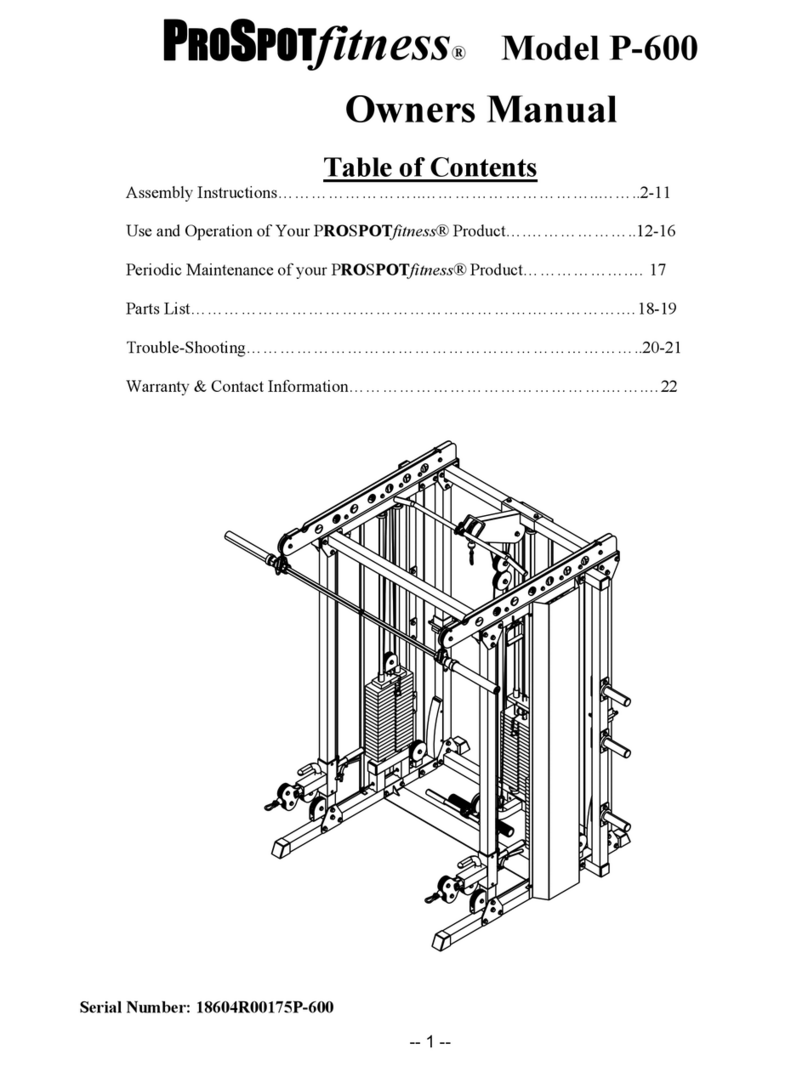
ProSpot Fitness P-600 User manual
ProSpot Fitness
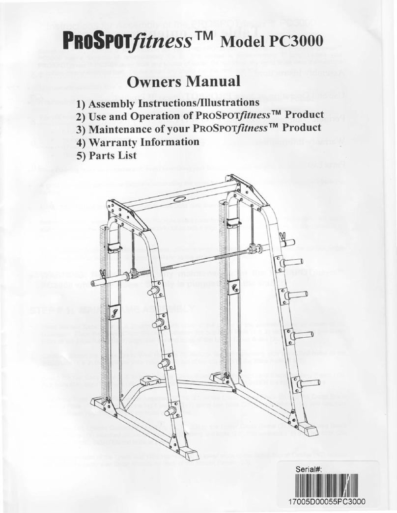
ProSpot Fitness PC3OOO User manual
ProSpot Fitness
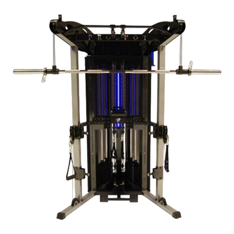
ProSpot Fitness FUSION HG-5 User manual
ProSpot Fitness
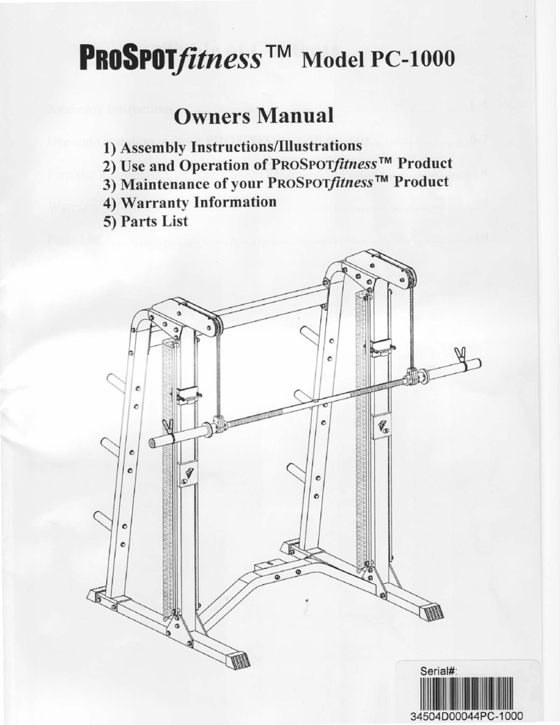
ProSpot Fitness PC-1000 User manual

ProSpot Fitness
ProSpot Fitness P-50 User manual
ProSpot Fitness
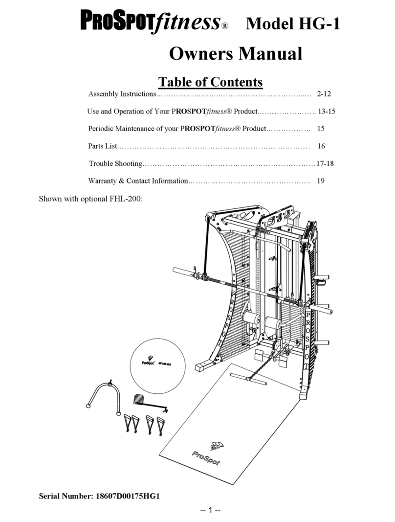
ProSpot Fitness HG-1 User manual
ProSpot Fitness
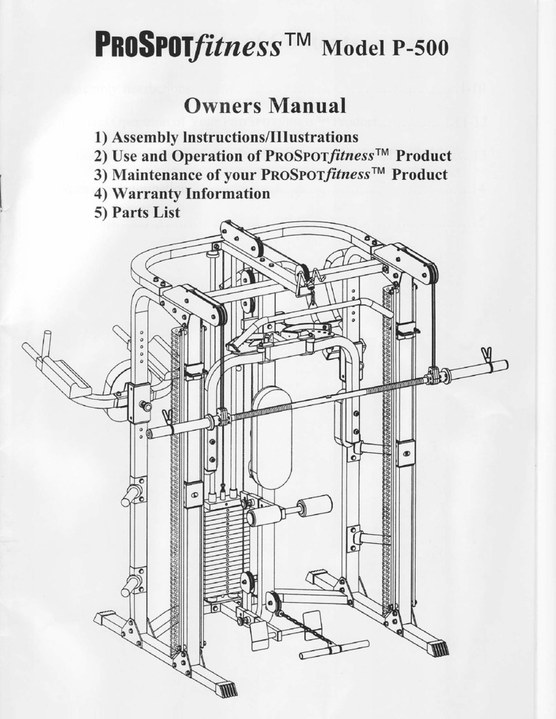
ProSpot Fitness P-500 User manual
Popular Fitness Equipment manuals by other brands

G-FITNESS
G-FITNESS AIR ROWER user manual

CAPITAL SPORTS
CAPITAL SPORTS Dominate Edition 10028796 manual

Martin System
Martin System TT4FK user guide

CIRCLE FITNESS
CIRCLE FITNESS E7 owner's manual

G-FITNESS
G-FITNESS TZ-6017 user manual

Accelerated Care Plus
Accelerated Care Plus OMNISTIM FX2 CYCLE/WALK user manual


