ProSpot Fitness P-500 User manual

PnoSP
olfitne,ss
rM
ModerP-5oo
Owners
Manual
1)Assemblylnstructions/Illustrations
2)UseandOperationofPnoSrorf/zessrM
3)Maintenance
ofyourPnoSroty'lzessrMProduct
Product
4)WarrantyInformation
5)Parts
List

Table
ofContents
Assembly
Instructions. ........1_10
Useand
Operation
ofYour
PnoSroffrnessrM
product.
..
.....
........1
|_12
Periodic
Maintenance
ofyour
pnoSror/aessrM
product.
....
..
....
.....
.I3
Warranty
Information. .....14
Partslist.... ...........15

lnstructionsforAssembly
ofthePROSPOT/tnessrM
P-500
. Beforeassembly,choosea safelocationforyour
PROSPOTJitnessrM
P-500.ThePROSPOTlrzessn
P-500hasa footprint
of approximately8'x 8'. The barbellis approximately7' long.
Locate
your
PROSPOTlrzessnP-500awayfromanysource
of water.
Do notallow
anyliquid
to be nearthe
machineorspilledonanyelectrical
part.
Donotinsert
anyobjectintothe
electricalbox.
. Approximate
assemblytimeis1-1l2hours.
. Aflat
areaof9'x9'willberequiredtoassembleand
properly
usethePROSPOT/itressrM
P-500.
. Youwillneed
thefollowingtoolsandahelpertocomplete
theassembly:
. 5mmAllenWrench
. 14mmBoxEndWrench
. 17mmBoxEndWrench
. 19mmBoxEndWrench
. FloorPadding,
such
ascardboard,
toavoidscratching
your
floorduringassembly.
. A goodpair
ofscissorswillbehelpfulinseparating
the
parts
from
oneanotherwhile
re-:, 19
themfromthecartons.
r HANDTIGHTEN
allbolts.DONOTfully
tightenboltsuntilinstructed
todoso.
. Before
assembly,separate
andidentifytheright-sided
parts
fromtheleft-sided
parts.
These
.61sa-e
easily
distinguishedby
the
manner
inwhjchthe
pre-drilled
holesalignwith
corresponding
rals :- a.e
identified
by
"1"
&"R"
stickers.
o ThePROSPOTfitnessrM
P-500usesseveral
differentlengths
of bolts.Becarefulto use
:^e::..e.t
length
ofboltcalledforateach
stepofassembly.Referto
thesizingcharts
provided.
o WARNING: Never perform any maintenance on the PROSPOffiressn P-500
whilethePower
Supplyis plugged
into
thewatl
!!!

Upright
Guidepost
Assembly
Diagram
Leat Locki.g Slide.
Right Lockihg Sli.te.

STEP#1: MAINFRAMEASSEMBLY
1. Placethe two BaseRails
(1 & 2) oppositeeachother
in the centerof the assemblyarea as shown
in the
lllustration.PlacetheLowerCrossBrace
(3)
betweenthetwo
BaseRails
(1
&2) so
that
theside
pre-drilled
holes
ofthe
BaseRails
(1
&2)alignwiththeend
holesoftheLowerCrossBrace
(3).
2. Carefully
threadtheCross
BraceWireHarness
(8)
through
thecorresponding
side
pre-drilled
holesoftheBase
Rails
(1
&2)then
pull
the
WireHarness
(8)
out
ofthetopholesoftheBase
Rails
(1
&2).
3. Attachthe two Base Rails
(1 & 2) to the LowerCrossBrace(3) usingtwo CrossBraceBackingPlates
(13),
four
bolts
(22),
eight
washers
('18)
andfournuts
(20)
asshown.
HANDTIGHTENtheboltsatthistime.
4. Attachthe RightUprightGuidepost
Assembly
(7,10,23\to the RightBase
Rail
(2)usingtwo UprightSupport
Plates
(6),
fourbolts
(22),
eight
washers
(18)
andfour
nuts
(20)
asshown.
HANDTIGHTEN
theboltsatthistime.
5. Attachthe
LeftUprightGuidepostAssembly
(9,
12,23)totheLeftBaseRail
(1)
using
two
Upright
SuppurtPlates
(6),
four
bolts
(22),
eightwashers
(18)
and
fournuts
(20)
asshown.HANDTIGHTENthebolts
atthistime.
6. Slidethe
VKRSlidingAdjuster
('111)
uponto
theleftoneofRearUprights
(4)
asshown.Pullthehandle
onthe
screwdown
pullpin
(68)
previously
installed.Thiswillallowthe
VKR
SlidingAdjuster
(11'l)
toslide
up.
Release
the
pin
tolock
in
place
andsecure
byturningknobclockwise.
7. AttachtheVKRFrame
(59)
tothe
VKRSlidingAdjuster
(111)
using
twobolts
(110) fourwashers(18)
and
two
nuts
(20)
asshown.
Tightentheboltssecurely.
8. AttachtheleftRearUpright
(4)
totheLowerCross
Brace
(3)
andlheCross
BraceBacklngPlate(13)
attachedon
theLeftBaseRail
(1)
usingtwobolts
(22),
fourwashers
(18)
andtwonuts
(20)
asshown.
HAND
TIGHTEN
the
boltsatthistime.
9. SlidetheChin-upBarSlidingAdjuster
(1
12)upontotherightone
ofRearUprights
(4)
asshownPullthehandle
onthescrew
down
pullpin
(68)
previously
installed.
ThiswillallowtheChin-upBafS
idngAdtuster(1
'12)
toslide
up.Releasethe
pin
tolockin
place
andsecurebyturning
knob
clockwise.
10. AttachtheChin-upBar(61)tothe Chin-upBarSlidingAdjuster
(1
12)usingtwobolts
(
11
0) fourwashers
('18)
and
twonuts
(20)
asshown.
Tighten
theboltssecurely.
11. AttachtherightRearUpright
(4)
totheLowerCrossBrace
(3)
andtheCrossBraceBackrngPlate
(13)
attached
ontheRightBaseRail
(2)
usingtwobolts
(22),
fourwashers
(18)
andtwo
nuts
(20)
assholvnHANDTIcHTEN
theboltsatthistime.
12. Plug
together
bothof
the
CrossRailWireHarness
(8)
tolower
endsoftheSpiralSignalCables
(46)
located
just
underthe
perforated
SliderShieldsonbackoftheScreen
Panels
(23).
'13.
AttachonePulley
Support
Frame
(17)
tothe
Left
Upright
GuidePost
(12)
usingtwobolts
(22).
four
washers
(18)
andtwo
nuts
(20).
HANDTIGHTEN
theboltsatthistime.
'14.
CarefullythreadtheLeftWeightBarKnuckle
(44)
upthrough
the
rectangular
cutoutinthePulley
SupportFrame
(17).
CarefullyflextheLeftWeightBarCables
(24)
sothatthecables
arebetweentheiwopuliey
support
plates
and insertintothe grooves
ofeachcorresponding
pulleys.
Be sure that the cables are straight and uncrossed
and pulleys
movesmoothly.
15. Attach
the
twosmall
plasticpipes
(15)
tothePulley
Support
Frame(17)
using
twobolts
(34).
four
washers
(38)
andtwonuts
(35)
asshown.Tighten
thebolts
securely.
16. Repeatsteps11-13ontherightsideof
the
PROSPOTlirrressrMP-500.
'17.
Attach
thetwoRearUprights
(4)
andtheTopBeam
(60)
tothetwoPulley
SupportFrames
(17)
usingfour
bolts
(28),
eightwashers
(18)
andfournuts
(20)
asshown.HAND
TIGHTEN
thebolts
at
this
time.
18. Attach
thePecDeck
SupportPost
(16)
andthe ElectronicBoxLocating
Plate
(5)
totheLower
CrossBrace
(3)
using
two
bolts
(22),
fourwashers
(18)
andtwonuts
(20)
asshown.
HANDTIGHTENthebolts
atthistime.
19. AttachthePecDeck
SupportPost
(16)
totheTopBeam
(60)
using
a bolt
(51),
twowashers
(18)
and
a nut
(20)
asshown.HANDTIGHTEN
theboltsatthistime.
20. Tighten
all boltsand nuts usedfor assembly
in previous
steps.
21. Insertbothof theGuide
Rods
(77)
intoeachof theGuideRodCups
(74)
located
onthe lowerendofthePec
DeckSupportPost
(16).
SlidetheWeightStacks
(67)
onto
theGuideRods
(77)
and
carefully
slide
themto the
bottom.SlidetheWeightTopPlateAssembly
(63,
70)ontotheGuideRods
(77)
andguide
themdown
sothat
theyrestontopof theWeight
Stacks
(67).
InserttwoAllenbolts
(71)
into
thethreadedholesintheGuideRod
CupPocketsofthePecDeck
SupportPost
(16).
Tightensecurely.

23.
24.
Insert
theSelect
Pin
(65)
intothedesired
holeinthe
CenterGuide
Rod
(70)
asshown.Carefullytolockthe
pin
in
place.
Place
theGuide
RodTopPlate
(73)
ontopof thetwoGuideRods
(77)
andslidethetwoGuide
RodCups
(74)
onto
theGuideRods
(77)
withdownward
pressure.
lnserttwoAllenbolts
(71)
into
thethreadedholesin
theGuide
RodCupPocketsoftheGuide
RodTopPlate
(73).
Tightensecurely.
Attachthe Pec Deck SupportFrame (62)and the Pec Deck BackingFrame(64)to the Pec DeckSupportPost
(16)
usingone
longerbolt
(57),
oneshorterbolt
(58),
fourwashers
(18)
andtwonuts
(20)
asshown.
Besurethis
assembly
is centeredand levelandthentighten
theboltssecurely.
STEP#1: MAIN
FRAME
ASSEMBLY
a3-
69
e0
18

STEP#2: SENSORWEIGHTBARINSTALLATION
'1. Standinganfrontof thePROSPOTlrressruP-500.
lnsert
oneendandthentheotherendof the
SensorWeightBar
(25)
intotheKnuckles
(42
& 44).Slide
the
knuckles
ontothe
Bar
untiltheyrest
snuglyagainstthe
preinstalled
sensor
retaining
collars
(45
&48)
ateachendoftheSensorWeight
Bar
(25).(There
isarotationlimiting
pin
that
protrudes
from
thebottomoftheSensorWeightBar
(25)
thatmust
fit
throughaslot
intheknuckles
(42
&44)asitisslidinto
position).
2. PlaceonePlasticLockingSleeve
(39)
ontoeach
endof
theSensorWeightBar
(25)
andslidethem
inwardsuntiltheybuttupagainstandsecurethe
WeightBar
CableKnuckle
(42
& 44)inplace.
TightenPlasticLockingSleeveboltssecurely.
3. PlaceanOlympicAdapter
(30)
ontoeachendofthe
Sensor
WeightBar
(25)
andslide
them
onto
the
BaruntiltheytouchthePlasticLockingSleeves
(39).
SlideanOlympicAdapterRetainingPlug
(33)
ontoeachendoftheSensor
WeightBar
(25)
so
thattheyalso
go
inside
oftheOlympicAdapters
(30).
SecuretheRetaining
Plugs
(33)
withtwoAllenbolts
(29),
two
flat
washers
(36)
andtwospring
washers
(86).
4'AttachtheUpperCrossBrace(,l1)tothetopofthetwoRearUprightS(4)usingfourbo|ts(28)'eight
washers
(
18)andfournuts
(20)
asshown.HANDTIGHTENtheboltsatthis
time.
5. Attach
the
Lat
SupportRail
(76)
tothe
Pec
DeckSupportPost
(16)
usingtwobolts
(53),
four
washers
(18)
andtwonuts
(20)
asshown.HANDTIGHTENtheboltsatthistime.
6. AttachtherearendoftheLatSupportRail
(76)
totheUpper
Cross
Brace
(1'1)
andtheGuideRod
TopPlate
(73)
usingtwobolts
(22),
foutwashers
(18)
andtwonuts
(20)
asshown.HANDTIGHTEN
theboltsatthistime.
7. InserttheendboltoftheLatCable
(80)
downthroughthe
pre-drilled
holesinthemiddle
of
the
Upper
CrossBrace
(11)
andtheGuideRodTopPlate
(73)
andthenthread
theendbolt
into
thethreaded
hole
ontopoftheCenterGuideRod
(70)
andsecuretheboltwith
the
lock
nut
provided.
8. AttachthefourSideWeightPlateHolders
(14)
tothetwoRear
Uprights
(4)
usingeightbolts
(53),
sixteenwashers
(18)
andeightnuts
(20)
asshown.Tighten
theboltssecurely
9. Attach
the
VKRBackrest
Cushion
(79)
totheVKRFrame
(59)
usingtwobolts
(84)
andtwowashers
(36).
Tightentheboltssecurely.
10. Attach
the
VKR
ArmPads
(81
&83)totheVKRFrame
(59)
using
four
bolts
(85),
fourflatwashers
(36)
andfour
springwashers
(86).
Tightentheboltssecurely.
11. Attachthe
two
VKR
Handlebars
(82)
totheVKRFrame
(59)
usingtwobolts
(84)
and
twowashers
(36).
Tightenthe
boltssecurely.

STEP#2: SENSOR
WEIGHT
BARINSTALLATION

STEP#3: PECDECK
ARMSAND
CABLESINSTALLATION
'1. AttachonePecDeckArm
(87)
and
theLeftPecDeckAdjustingPlate
(88)
tothePecDeckSupport
Frame
(62)
usingabolt
(52),
two
washers
(90)
andanut
(92)
asshown.Tightentheboltssecurely.
2. AttachtheotherPecDeck
Arm
(87)
andthe
RightPecDeckAdjustingPlate
(100)
tothePecDeck
SupportFrame
(62)
usinga bolt
(52),
two
washers
(90)
anda nut
(92)
asshown.
Tighten
thebolts
securely.
3. Fastenthetwoendsofthe
PecDeckCable
(721to
thecamarmsofthetwoPecDeckArms
(87)
using
twoshoulderbolts
(102)
asshown.Tighten
theboltssecurely.
4. LaytheLowRowConnector
Cable
(96)
onto
the
pulley(99)
locatedinthelower
position
oftheDouble
PulleyAssembly
(78)
sothatthe
looseend
points
tothefrontofthemachineandtheninsertthecable
endbetweentheretaining
tabsofthePec
DeckFreePulleyCover
(66)
andaligntheholesandsecure
withabolt
(106),
two
washers
(90)
andanut
(92).
5. Lay
the
LowRowConnectorCable
(96)
underapulley
(99)
and
press
downinto
the
pulley
socket
(B)
onbackof
thePecDeckSupport
Post
(16)
andalignthe
holes.Insert
a bolt
(95)
into
the
holes
and
securewithtwo
washers
(90)
andnut
(92).
6. Slidethe
LegFrame
(103)
down
intothesocket
(C)
locatedontheleftsideofthe
Pec
DeckSupport
Post
(
16)
as
shown.Pullthehandle
onthescrewdown
pullpin
(68)
previously
installed.Thiswillallow
theLegFrame
('103)
to slidedown.Releasethe
pin
to lockin place
andsecurebyturningknob
clockwise.
7. Slide
a FoamRoller
(104)
ontoeach
sideoftheLegFrame
(103)
andinserta RollerRetainingCap
(101)
intoeachsideofthetube.
8. SlidetheFootBoard
(94)
into
the
socket
(D)
locatedonthebottomofthe
Pec
DeckSupportPost
(16)
asshown.Pullthe
handle
on
thescrewdown
pullpin
(68)
previously
installed.Thiswill
allowthe
Foot
Board
(94)
to
slidein.Releasethe
pin
tolockin
place
andsecurebyturning
knob
clockwise.
9. AttachtheBackrestCushion
(98)
tothePecDeckSupportPost
(16)
usingtwobolts
(108)
andtwo
washers
(36).
Tightenthe
bolts
securely.
10.
Attach
theArm
Pads
(97)
tothePecDeckArms
(87)
usingfourAllenBolts
(105)
andfourrubber
bumperwashers
(107)
asshown.Tightenthe
boltssecurely.
11.ConnecttheLowRowPullBar
(93)
tothe
LowRowConnector
Cable
(96)
usingtwocableclips
(89)
andaChain
(91).
12.
Connectthe
LatPullBar(109)
tothe
LatCable
(80)
usingacableclip
(89).
IMPORTANT:1. Beforeeach use,check the CableClips (89)on the end of the cablesto
ensuretheyare
securely
fastened.
2. Beforeeach use, pull the cablesa few timesto be sure that the cablesmovesmoothly
overthe pulleys.
lf the cablesdo not movesmoothly,find and correctthe problem.
3. Forsafety,
when the Lat Pull Bar('t09)
is not being usedeitherremove
it completelyor
leaveit attachedto the cableand rest it in the bar holder providedon the lat support rail
(76).
4. Note: In this manual when referringto Left and Right side of unit, the left and right
perspective
are
from the outside,
facingthefront of the unit.

STEP
#3: PEC
DECK
ARMS
AND
CABLES
TNSTALLATTON
68

PROS
POT
fitnes
srMP-500
Bolts
&
Bushings
Size
Chart
#57
QTY:7 #22
QTY:24
#95
QTY:72
#28
QTY:8
#38
QTY:8
#52
QTY:2
#29
QTY:2
#57
QTY:7
#77
QTY:4
#36
QTY:7O
rA)
\z
8/76 mm
5,/7Omm
--9--

PROSPoTfitnessrM
P-500
#8s #s3 #70s #708
QTY:4 QTY:IO QTY:4 QTY:2 #34
QTY:4
#58
QTY:7
#90
QTY:38
7O,/2O
mm
#20
QTY:53
@e
M70
#78
QTY:7O6
#92
QTY:79
#770
QTY:4 # 706
QTY;7
#84
QTY:4
#86
QTY:8
#35 n ,,N
erY:4 -4+
(O+
@ u \z
MS 8mm
a
q
I
ttg
Nt0
M72 72/24 mm
-- 1n--

!lRead!!ThisPageBeforeUsing
Your ProSpotlitness
rMProduct
SafeUseof Your ProSpotJitnessrMProduct
1. CAUTION:
Thismachineinvolvestherisk of possible
iniurv by itsuser.
THE FOLLOWING RULESSHOULD
BE CARFULLY FOLLOWED:
Consult a physician or other healthcare
provider before beginning an
exercise
program.
If you arein badhealthor arehandicapped,ask for the opinion of your
physician
andexerciseonly
under
qualified
supervision.
Discontinueto exercise
if you experienceanylight-headedness,dizziness
or shortnessofbreath and
consult
yourphysician.
2. Keep small childrenandothersat a safedistance
from all moving parts.
The up and down movementof the weights can be dangerous.Never
allow your fingers,toes,hair, otherbodypartsor looseclothingto come
near weights while they are in motion. Never attemptto exercisewith
moreweight thanyou are
physicallyableto handle. Periodicallyinspect
your machine to ensureall parts are free from defect and are fully
operational.Check
all fastenersto make
surenonehave
loosened
with use.
Tightenanyloosefastenersif necessary.
3. Warning: Neverperformany maintenanceon theunit while thepower
supplyisplugged
into thewall.

1.
7.
2.
3
5.
6.
8.
10.
't1.
14.
15.
17.
'18.
User
Instructions
forthe
P-500
Do
notallow
any
liquidtobenearthemachine
orspilled
onanyelectrical
part.
Donotinsertany
foreignobject
into
theelectrical
boxorattempttoopen
it.
lfyou
haveany
questions
orneedhelprefertoourwebsiteat www.
DrosDotfitness.com
Connectthepower
supplyto a standard
110volthouseholdcurrent.lt is recommended
that
surge
protection
is usedto help
protect
andextendthelife
oftheElectronic
Boxoftheunitfrom
power
surgesand
lightingstrikes.A flashing
green
light
willappearontheElectronicBoxwhen
power
ison.
Afterassemblyoi your
P-500becomefamiliarwiththeGrabandGofr systembefore
placing
weightsonthebarbell.
Assume
anormalstarting
position
for
your
desired
freeweight
exercise.
Rotate
thebarbellsothattheTouchSensor
Stripembeddedin thebarbell
is touching
your
fingertips.ltisnecessarytomaintainskincontact
with
thetouchsensorstripthroughout
your
free
weight
exercise.Once
you
have
grasped
the
Touch
SensorStrip,
you
will
hear
asoft
'click'
anda
solid
redlightwillappearontheElectronicBox
in
additiontothe
flashing
green
power
light.
Whilestill
grasping
thebarbell,
liftita minimumof%",usinganevenupward
lifting
motionon
both
sidesofbarbell.Thisupwardmovement
willdisengage
the
locking
mechanism.lf
you
have
performed
thisstepcorrectly,thebarbellwill
nowbeunder
your
control,thecableswillmove
freelyoverthe
pulleys
andtheSlider
Knuckleswillslide
smoothlyupanddowntheGuidePosts.
Youcannowsafely
perform
anyfree
weightexercisewithout
theneed
ofa spotter.SimplyGrab
andGorM!
Remove
fingertipsfrom
the
TouchSensorStriptolockthebarbellin
place.
Alwaysmaintaincontrolofmovementofthebarbell.
Do
notallowbarbellordumbbellstoswing
against
machineframe,
asthis
maycausedamagetothefinish.Donotattempt
tothroworslam
thebarbell
attachedto thecables,asthismayresultin damageto thelockingmechanism.
IntentionalmisuseoftheP-100willvoidanyandallwarranties.
Once
you
are
familiarwith
the
GrabandGorMsystem,
position
barbell
intheproper
starting
position
for
your
desiredexercise
Makecertainthebarbellislevelbeforeloadingweight
plates.
Levelthebarbellbyraising
upone
endofthebarbelluntillevel.
(The
P-500isdesignedwitharatchetingfeaturethatallowsit
tobe
manually
raised
fromsidetoside.)
Or,levelthebarbell
by
grasping
itwithbothhands,making
surethe
fingertips
makecontact
with
thetouchsensorstrip.Liftthebarbellupwardaminimum
of
%"to release
itfrom
thelocking
mechanismand
adjustbarbelluntillevel.Oncethebarbellis
level,
release
yourgrip
ontheTouch
Sensor
Strip
to engagethelockingmechanism.Load
weightsevenly
onbothsidesofthe
barbell.
Secureallweight
plates
witha springclipor
locking
collar.Y,,'r re
nowreadytobegin
your
free
weightexerciseroutine.
12.
'13.
Never
attempt
toIiftmoreweightsthan
yo
theBarbell. 'r safelvha, i i ,ver
DUt
morethan750 lbs
on
Beforeremovingweight
plates
from
weighte. jrbell,
mak€ l i ,
barbellisinalevel
position.
Insertweightselector
pin
intothe
weightstack
to add
| ',il. , e forusewiththehigh-pulley
exercisesandthe
low-pulley
exercises.
Toperform
cableexercisesonPBL-20Benchunitattachlov,
l'inch cable
to low-pulley.Make
surecableistightby
pulling
out
#94Footboardasastopand
r--ater
forBench.
Whendoinghigh-pulleyexercises,
pullout
#103LegFrametoholddownUseror
il:*rnch.
AdjustVKR&Chin-Upheightby
pulling
the
selector
pop-pin
and
then
tighten
knob.
to.

MaintenanceofProSpotfitnes{M
Product
Intro: Our productsare madeof durablematerialsand have beenfactory testedto assure
proper function and reliability. Along with our EquipmentWarranty,this gives the
owner of our product the confidence of a long lasting relationship r.vith
ProSpolffru
essrMInc. Our systems
aredesignedin away to allow easyreplacementof
partsboth mechanicalandelectrical
if the needshouldeverarise. If you area ne\\
ownerof a ProSpotf/nessrM
system,tkee important
thingsneedto bedoneto assure
prompt serviceunder the walranty:
1. Fill outandfaxormailto usyour
ProductWanantyRegistrationCardalong
withacopyof your
sales
receipt
(proof
of purchase)
if this.hasnotbeendone
by
your
dealerattimeofpurchase.
2. Yoursystemneeds
tobesetup
properly
accordingtotheassemblymanual.
3. Followuserinstructionson
howtoproperly
usethesystem.
Maintenance
Program
Note: Our products
arerecommendedfor climatecontrolledenvironments.Outdooruseis not
recommendedandwill void thewarranty.
Carefullyinspectmachinebeforeeach
useto determinethatit isfreefrom defects.
Do NOT usemachineif youfind:
1. A loose,brokenor frayedcable (needs
to bereplaced)
2. A loose,
broken
or frayed
power
cord
- (needs
to bereplaced)
3. Any broken,cracked,torn, frayedor defective
partof themachine
- (needs
to be
replaced)
4. Checkall fasteners
to makesurenonehaveloosenedwith use.Tightenanyloose
fasteners.
5.
6-
Checkfor freemovementof all cable
pulleys. Adjust if necessary.
Make sure
guiderodsandupright guideposts
arefreeof dirt, adhesiveresidue
or
moisture. Standard silicone lubricant (purchased from fitness dealers) is
recommendedfor thelubricationoftheseparts.
Warning: Never performanymaintenanceon theunit while thepowersupply
is
plugged
intothe
wall.

WarrantyInformation
EachPnoSeo/irressrMProduct
comeswith alimited parts
replacement
wananty. Pleasereferto
the actualwanarty card included with your systemfor specific coverage.If you haveany
questions
about
performance
underthislimitedwananty,
please
writeusat:
PnoSrorlirz€.r.r,Inc.
Attn: WarrantyService
1325
Oakbrook
Drive.
SuiteE
Norcross,GA30093
Office
(770\446-9299
Fax (770)-446-7213

PROSPOTfitness
rM
ModelP-500PartsList
Assy # Description Qtv
1LeftBaseRail 1
2RightBaseRail 1
3LowerCross
Brace 1
4RearUpriqht )
5ElectronicBoxLocatino
Plate 1
6UpriqhtSupportPlate 4
7Riqht
LockingSlider 1
8Cross
BraceWireHarness
9LeftLockingSlider 1
'10 RiqhtUpriqhtGuide
Post 1
11 Uoper
CrossBrace 1
12 LeftUoriohtGuidePost 1
13 Cross
BraceBackinqPlate
14 Side
WeiohtPlateHolder 4
15 Small
PlasticPipe 4
16 PecDeckSuoDortPost 1
17 PullevSupport
Frame
18 FlatWasher12124mm 106
'19 SpacinqDisc d
20 Nylon-lockNut M12 53
V-shaped
Rubber
Bumper
Rinq
22 HexHeadBoltM12x '105
mm 24
23 ScreenPanel 2
24 Weioht
Bar
Cable.
left 2
SensorWeiohtBar 1
HexHeadBoltlvl12x 150mm 4
Big
Pulley,
double-groove
28 HexHeadBoltNrl'l2x '1
10mm 8
29 AllenBoltlVlSx40mm 2
30 OlympicAdapter
3t SprinqClip.50mm Dia 2
32 RubberBumperRinq50/80
mm 2
33 OlympicAdapterRetainingPlug 2
34 CableKeep
bolt
M5x
60
mm
35 Nvlon-lockNutM5
36 FIatWasher
8/16
mm 10
37 RoundInnerPluo,45mmDia
38 FlatWasher5i10mm I
39 PlasticLockino
Sleeve 2
40 Solenoid 2
41 FootEndCao 75x45 mm 4
42 Riqht
Weiqht
BarKnuckle 1
43 RiqhtSliderKnuckle 1
44 LeftWeiohtBarKnuckle 1
SensorRetaining
Collar,
right 1
46 SpiralCable 2
47 WeiqhtBarCable.riqht 2
48 SensorRetaininq
Collar,left 1
49 SliderKnuckleRetaininqPin 2
50 CotterPin 2
51 HexHeadBoltM12x100mm 'l
52 HexHeadBolt
M10
xI10mm 2
53 HexHeadBoltM12x 70 mm '10
Nvlon
lnnerPluq
75x45mm 9
55 LeftSliderKnuckle 1
5t) SliderlnnerSleeve 45175mm
Assy
#Description Qtv
58 HexHeadBolt
M12x 75mm
59 VKRFrame
60 .Tgp
Bg€m
61 c!t! ltp
Bat
62 PecDeck
Support
Frame
63 WeightTopPlate
64 PecDeckBackinoFrame
65 SelectPin
oo Pec DeckFreePullev
67 WeiqhtStack '19
68 ScrewDownPullPin 4
69 VKRFramelnnerSleeve
70 CenterGuideRod
71 Hex
HeadBoltM8x 15mm 4
PecDeckCable 1
73 GuideRodTopPlate
74 Guide
Rod
Cup 4
75 BackingPlate 4
76 Lat
SupportRail
77 WeiqhtStackGuideRod 2
78 DoublePullevAssemblv
79 VKRBackrestCushion
80 Lat
Cable
81 VKRArmPad,left
82 VKRHandbar 2
83 VKRArmPad,riqht
84 Hex
HeadBolt
lilS
x20mm
85 HexHeadBoltlil8x75mm
86 SprinqWasher
8
mm 8
87 PecDeckArm 2
88 PecDeckAdiustinqPlate,
left
89 CableClip 3
90 FlatWasher10/20mm 38
91 Chain
92 Nylon-lockNut M10 19
93 Low
RowPullBar
94 Foot
Board
95 HexHeadBoltNil'10
x45mm
96 LowRowConnectorCable
97 PecDeckArmPad 2
98 Backrest
Cushion
99 SinglePulley 12
100 PecDeckAdjustingPlate,
riqht
't01 RollerRetaininq
Cap 2
'102 ShoulderBoltM8x19.5mm
'103 LegFrame
104 FoamRoller
105 Allen Boltl\il8x 85 mm
106 Hex
HeadBoltl\i!10x 35mm 1
107 RubberBumper
Washer
108 AllenBoltNilSx75 mm 2
109 LatPullBar I
110 HexHeadBoltM12x80mm 4
111 VKRSlidinoAdiuster 'l
't
12 Chin-upBarSlidinqAdiuster 1
113 Electronic
Box
Protectino
Cover 1

HOWTOUSESPOT
BLOCKS
UsingSpotBlocksis
quick
andeasy.Justfollowtheseinstructions:
ToUse
Spot
Blocks
asaSecondarvLockinqDevice
1. Before
positioning
SpotBlocks,
place
thebarbellintothelowest
position
forthe
exercise
you
willbe
performing.
2. Oncebarbellis
placed
indesired
position,
lower
Spot
Blocks
so
thatthey
aretouchingthetopofthesliderlockingblock
(the
blackbox
withthe
ProSpot
Fitness@logoonit).TomoveSpotBlocks,
placeyour
index
and
middlefingers
underneath
thefinger
grip
and
your
thumbonthe
push-
releaselever.Push
inthe
push-release
lever
with
your
thumbandmove
intodesired
position.
Releasethe
push-release
levertolocktheSpotlock
in
place,
then
ensuretheyaresecurely
locked
beforeusingbarbell.
3. Oncein
place,
thebarbellcannotbeloweredbeyondthe
position
ofthe
Soot
Blocks.
ToUseSpotBlocksasaTraininqAid
1. Determinewhere
your'stickingpoint'
isfordesired
exercise.
(The
'sticking
point'
referstothe
specific
portion
ofthemovementwhere
you
are
the
weakest
andstruggletomovethebarbell
upwardany
further.)
2. Positionthe
Spot
Blocks
at
thebeginningof
your'stickingpoint'.(Refer
to
f2 aboveonhow
tomove
Spot
Blocks.)
3. Perform
thedesiredexercise
with
Spot
Blocksin
place.
Youwillnot
be
abletolowerthebarbelow
your'stickingpoint',
causing
your
musclesto
workharder
atthis
point.
Using
thistechniquewillstrengthenthisareaand
helptoeliminate
your
'sticking
point'.
ALWAYSUSE
SPOT
BLOCKS
Table of contents
Other ProSpot Fitness Fitness Equipment manuals
ProSpot Fitness
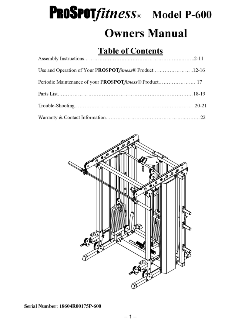
ProSpot Fitness P-600 User manual

ProSpot Fitness
ProSpot Fitness P-50 User manual
ProSpot Fitness
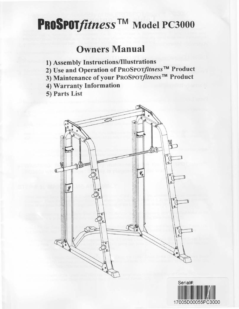
ProSpot Fitness PC3OOO User manual
ProSpot Fitness
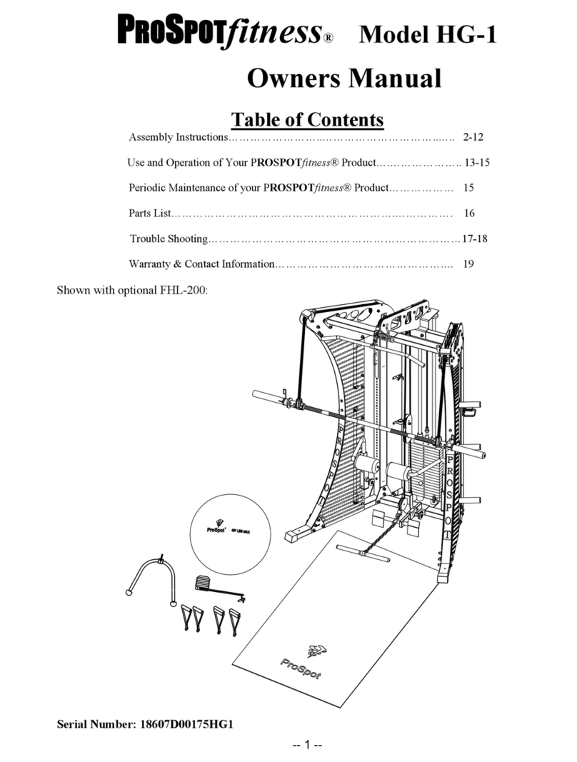
ProSpot Fitness HG-1 User manual
ProSpot Fitness
ProSpot Fitness FUSION HG-5 User manual
ProSpot Fitness
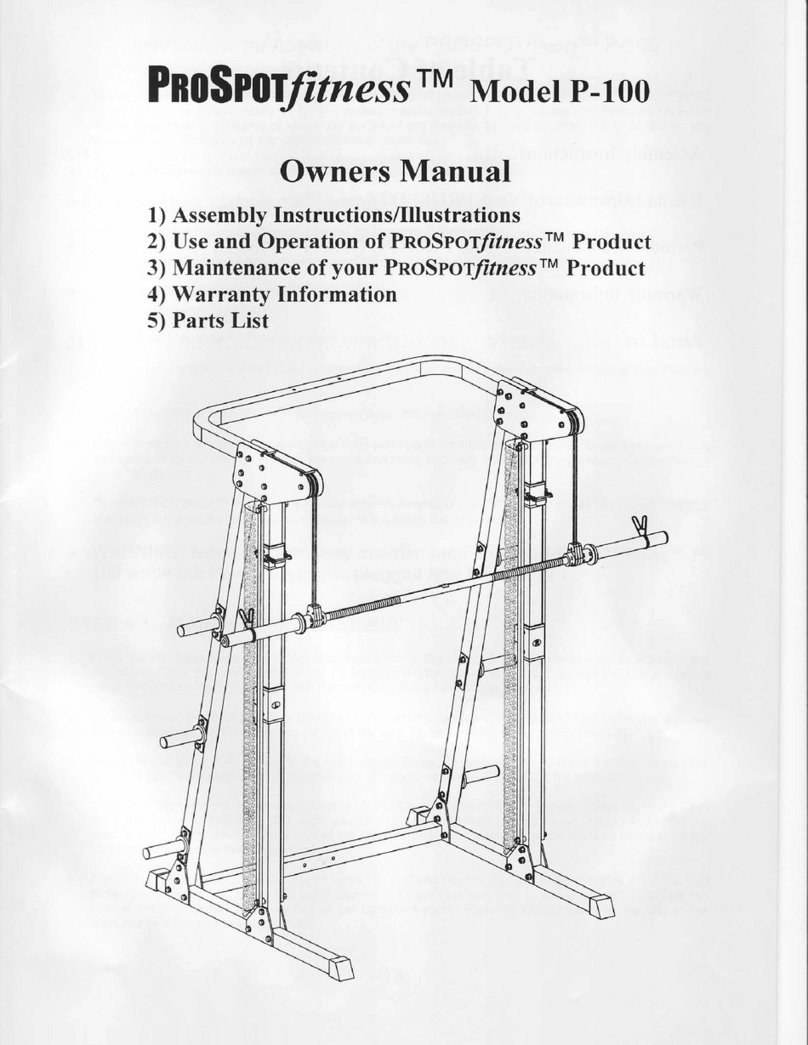
ProSpot Fitness P-100 User manual
ProSpot Fitness
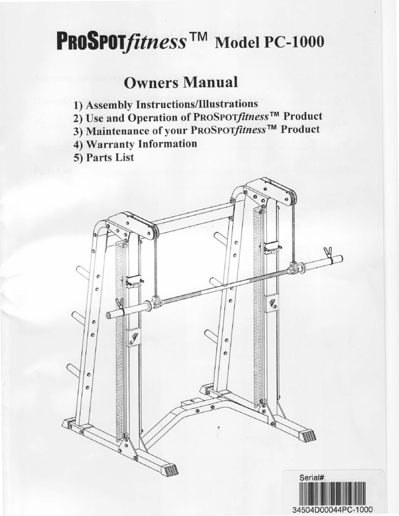
ProSpot Fitness PC-1000 User manual
Popular Fitness Equipment manuals by other brands

G-FITNESS
G-FITNESS AIR ROWER user manual

CAPITAL SPORTS
CAPITAL SPORTS Dominate Edition 10028796 manual

Martin System
Martin System TT4FK user guide

CIRCLE FITNESS
CIRCLE FITNESS E7 owner's manual

G-FITNESS
G-FITNESS TZ-6017 user manual

Accelerated Care Plus
Accelerated Care Plus OMNISTIM FX2 CYCLE/WALK user manual


