Italiano
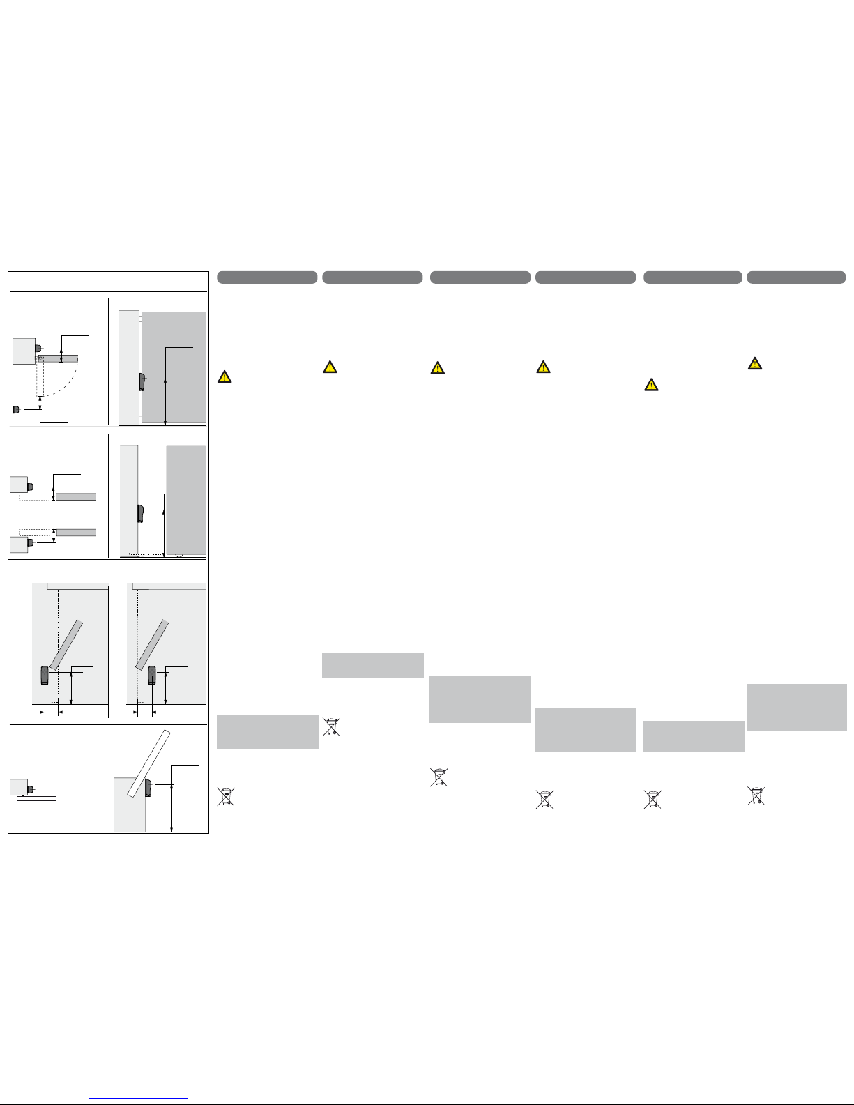
<700 mm
<150 mm
<150 mm
<300 mm <300 mm
<150 mm <150 mm
<150 mm
<150 mm
<700 mm
AVVERTENZE E PRECAUZIONI PER LA
SICUREZZA E L’USO
Il presente manuale è rivolto esclusivamente a
personale professionalmente competente.
Leggere attentamente prima di procedere con
l’installazione: un’errata installazione può
essere fonte di pericolo.
Conservare con cura questo manuale per
interventi futuri di manutenzione.
Prima di iniziare l’installazione verificare
l’integrità del prodotto.
Verificare che la superficie prescelta per
l’installazione sia solida e possa garantire un
fissaggio stabile.
Prima di collegare le fotocellule
accertarsi che la tensione di
ingresso sia uguale alla tensione di
uscita della centrale elettronica.
DESCRIZIONE PRODOTTO
E DESTINAZIONE D’USO
Questo prodotto è un dispositivo di sicurezza
destinato agli impianti di automazione per
cancelli, portoni, porte garage, barriere
stradali o similari.
Qualsiasi altro uso diverso dal quello descritto
è da considerarsi improprio e vietato.
Le fotocellule RF40 creano una barriera ottica
a raggi infrarossi modulati a fascio ristretto per
evitare fenomeni di riflessione e rispondere
alle normative vigenti.
Sono costituite da una scheda ricevente (RX)
e una scheda trasmittente (TX) integrate in
due contenitori schermati dai raggi solari che
possono essere fissati a parete o su coloninne
acquistabili separatamente.
Vengono normalmente installate ai 2 lati
dell’apertura: quando un ostacolo interrompe il
raggio a infrarossi, viene inviato un segnale
alla centrale elettronica che blocca o inverte il
movimento dell’automazione.
INSTALLAZIONE
a) Togliere il copriviti facendo leva nella parte
inferiore con un cacciavite per circa 1mm -
aggancio a scatto (Fig. 1)
b) Svitare le viti di fissaggio del coperchio alla
base (Fig. 2)
c) Togliere il coperchio (Fig. 3)
d) Predisporre la fotocellula per il passaggio
dei cavi sfondando i prefori sul retro (Fig. 6)
o nella parte inferiore (Fig. 7) della base.
Rispettare le caratteristiche di cablaggio
indicate nella tabella tecnica
e) Fissare la base alla parete o alla colonnina
tramite le viti e i tasselli in dotazione.
Accertarsi che la morsettiera sia nella
parte inferiore (Fig. 4)
f) Verificare le altezze e la direzione: TX e RX
devono essere allineati in posizione
frontale, sullo stesso asse e alla stessa
altezza (Fig. 5)
g) Collegare i fili in morsettiera: a fotocellula
alimentata e allineata si avrà un contatto
N.C .sui morsetti 1-3
h) Alimentare entrambe le schede RX e TX a
12/24V ac/dc come indicato da schema di
tensione.
i) Verificare il corretto allineamento delle
fotocellule: il led rosso deve risultare
acceso (per aperture superiori ai 3-4m è
necessario posizionare il coperchio con
lente integrata perché il led si accenda).
Interrompendo il raggio delle fotocellule il
led si spegne e il contatto del réle (morsetti
1-3) passa da N.C. a N.O.
Importante: per testare il corretto allineamento
delle fotocellule spostare il ponticello nella
modalità PORTATA RIDOTTA e accertarsi che
il led di allineamento resti correttamente
acceso. A test effettuato riportare il ponticello
in modalità PORTATA MASSIMA.
Utilizzo della fotocellula come dispositivo
comando di START
Per il collegamento della fotocellula come
dispositivo di comando utilizzare i morsetti 2-3
della scheda RX (contatto N.O.)
SMALTIMENTO
Non disperdere nell’ambiente.
Alcuni componenti elettronici
potrebbero contenere sostanze
inquinanti. Smaltire i materiali
attraverso i centri di raccolta previsti
e nel rispetto delle norme in vigore a
livello locale.
<700 mm
TIPOLOGIE DI APPLICAZIONE - INTENDED USE
APPLICATIONS - DESTINACIÓN DE USO
UTILIZAÇÃO DO PRODUTO- MONTIERUNGSARTE
English Français Español Português Deutsch
Cancello Battente
Swing gate
Portail Battant
Puerta batiente
Portão de braço
Schrankenbaum
Cancello Scorrevole
Sliding gate
Portail Coulissant
Puerta corredera
Portão de correr
Schiebetor
Porta da Garage - Garage door - Porte de Garage
Puerta de garaje - Porta de garagem - Garagentor
Barriera Stradale
Park barrier
Barrière routière
Barrera
Barreira de estacionamento
Schrankenbaum
GEBRAUCHSANWEISUNGEN
Dieses Handbuch ist an sachkundigen
Fachmännern gewandt. Bitte sorgfältig lesen
bevor Sie die Montierung anfangen: eine
fehlerhafte Installation kann gefährlich sein.
Behalten Sie es bitte in einem bestimmten Ort
im Falle zukünftiger Wartungseingriffe
Bevor Sie die Installation anfangen, die
Produktsunversehrtheit bitte überprüfen
Überprüfen, dass die Montierungsoberfläche
fest und geeignet für eine gute Installation ist.
Vor dem Anschließen der
Lichtschranke überprüfen, ob die
Ausgangsspannung aus dem
Kraftwerk gleich der Eingangs-
spannung der Lichtschranke ist.
ALLGEMEINES
Dieses Produkt ist eine Sicherheitsvorrichtung
für die Torantriebesanlagen sowie
Garagentorantrieben und Schrankenbäume
bestimmt. Jeder anderer Gebrauch ist
ungeeignet und verboten.
Bediengrät
Für die Verbindung der Lichtschranke als
Bediengerät (z. B. Öffnung des Tores beim
Durchlauf über die Lichtschrankenstrecke) bitte
die Klemmen 2-3 vom Empfänger benutzen
(Kontakt N.O.).
ENTSORGUNG
Nicht in die Umwelt werfen.
Einige elektronische Komponente
können Schadstoffe enthalten.
In den Recycle-Punkten entsorgen
mit Beachtung der herrschenden
Normen.
SAFETY INSTRUCTIONS
AND PRELIMINARY CHECKS
This manual is only for professional or
qualified installers.
Improper installation may cause serious
damage, follow all installation instructions
carefully.
Keep this manual for future consultation and
maintenance.
Before installing check the integrity of the
product. Make sure the chosen location is
suitable for a stable fixing.
Before connecting make sure the
photocells input voltage and the
pcb’s output voltage are the same.
DESCRIPTION AND INTENDED USE
This product is a safety device intended for the
automation of gates, garage doors, park
barriers and similar systems.
Any installation and/or use other than that
specified in this manual is forbidden.
The synchronized infrared-beam prevents
from interferences and does comply to the
reference regulations in effect.
RF40 photocells include a receiver RX and
transmitter TX integrated in UV proof cases for
wall or vertical mounting (mounting columns
available as accessory).
The photocells must directly face each other:
when an obstacle cuts the infrared beam, a
signal is sent to the pcb’s that stops or
reverses the movement.
INSTALLATION
a) Remove the screw covers by levering
the bottom with a screwdriver to about
1mm - snap hook (Fig. 1)
b) Unscrew the screws securing the casing
cover to the base (Fig. 2)
c) Remove the casing cover (Fig. 3)
d) Perforate the back or alternatively the
bottom casing base to push through the
cables (Fig. 6 and Fig. 7).
e) Comply with wiring specifications indicated
in the technical table.
f) Fix the casing base on the wall or on the
column using the supplied screws and
dowels. Make sure the terminal block is at
the bottom (Fig. 4)
g) Check ground height and orientation:
TX and RX must directly face each other
(Fig. 5)
h) Wire the cables to the terminals: you get a
NC contact on terminals 1-3 once the
photocells are aligned and powered.
i) Feed both RX and TX to 12/24V ac/dc
according to the voltage diagram.
j) Photocells must be properly aligned:
the red LED has to be ON (fit the cover
casing for entries over 3 – 4 m).
Breaking the infrared beam the LED turns
off and the relay contact (terminals 1-3)
turns N.O.
Important: Photocells are supplied with a
calibration jumper. In order to get a perfect
alignment move the jumper to LOW RANGE
mode and make sure the LED stays ON.
START command function (option)
The RF40 photocells can operate as well as a
START command.
Just connect terminals 2-3 on the receiver
interface RX (contact N.O.)
DISPOSAL
RESPECT THE ENVINRONMENT.
Dispose of the packaging and the
device properly at the end of its life
cycle, following the applicable laws
in the country where the device is
installed.
ADVERTENCIAS
Este manual es para el uso exclusivo de
personal cualificado y competente.
Lea cuidadosamente antes de instalar: el
empleo inadecuado puede ser causa de
situaciones peligrosas.
Aguarde este manual para consulta futura.
Antes de comenzar la instalación, compruebe
la integridad del producto.
Asegúrese de que el lugar elegido para la
instalación es robusto y puede garantizar una
fijación estable.
Antes de conectar las fotocélulas
compruebe que la tensión de
entrada sea igual a la tensión de
salida del cuadro de maniobra.
DESCRIPCIÓN Y USO
Las fotocélulas RF40 están diseñadas para
detectar obstáculos en instalaciones de
puertas, portones, puertas de garaje, barreras
o dispositivos semejantes.
Cualquier otro uso distinto debe ser
considerado incorrecto y por eso prohibido.
Las fotocélulas RF40 llevan la función
sincronismo para evitar interferencias y cumplir
con las disposiciones de seguridad en vigor.
Se componen de un módulo receptor RX y un
módulo emisor TX, protegidos por tapas
resistientes a los rayos infrarrojos.
Fijación a pared o peana.
Se recomienda instalarlas en sentidos
opuestos de la puerta: si una persona u objeto
interrumpe con su presencia el rayo de luz
emitido por el emisor, el receptor activa el relé
correspondiente, informando al cuadro de
maniobra, deteniendo o invertiendo asi el
recorrido de la puerta.
MONTAJE Y CONEXIONADO
a) Quite los cubretornillos.
Por medio de un desatornillador haga
presión en la parte inferior por 1 mm
(enganche a presión, Fig. 1)
b) Quite los tornillos de la tapa de
protección (Fig. 2)
c) Quite la tapa (Fig. 3)
d) Utilizando las plantillas suministradas,
realice los orificios apropriados,
dependiendo de la superficie de
fijación (Fig. 6 y Fig. 7). Respete las
características de conexionado como
se indica en la ficha técnica adjunta.
e) Fije la plantilla a la pared o a la peana
utilizando los tornillos y tacos
suministrados. La bornera debe
colocarse en la parte inferior (Fig. 4)
f) Compruebe la altura y el sentido: los
módulos TX y RX deben estar lo más
alineados posible (Fig. 5)
g) Introduzca el cableado y realice las
conexiones: una vez alimentada y
alineada la fotocélula se tendrá un
contacto N.C. en los terminales 1-3
h) Conecte la alimentación a ambos
módulos RX y TX a 12/24V ac/dc como
se indica en el esquema de tensión.
i) Compruebe la correcta orientación de
los módulos: el led rojo debe estar
encedido( para un alcance mayor de
3-4m es necesario colocar la tapa con
lente integrada). Al interrumpir el haz
infrarrojo el led se apaga y se abre el
contacto N.O. (terminales 1-3).
Importante: Las fotocélulas llevan de fabrica
un contacto de calibración.
Para comprobar el correcto funcionamiento
de las fotocélulas mude el contacto de
sitio, poniendolo en posición ALCANCE
REDUCIDO y asegurese de que el led quede
permanentemente encendido.
Función comando de START
(seleccionable)
Las fotocélulas RF40 disponen de la función
START, seleccionable mediante los bornes
2-3 del módulo receptor RX (contacto N.O.).
ELIMINACIÓN
NO DISPENSAR EN ELAMBIENTE
Algunos componentes de este
equipo pueden contener sustancias
contaminantes.
Elimine en centros de recogida
selectiva respetando las normas
locales vigent.
AVISOS DE SEGURANÇA
Este manual tem informações importantes
para a segurança de pessoas e por isso deve
ser utilizado exclusivamente por pessoal
qualificado e experiente.
A instalação ou uso incorreto deste produto
pode causar danos físicos e materiais.
Mantenha estas instruções num local seguro
para obras de manutenção ou futura
referência.
Antes de iniciar a instalação, verifique a
integridade do produto.
Certifique-se de que o local escolhido para a
instalação é robusto e pode garantir uma
fixação estável.
Antes de ligar as fotocélulas
certifique-se de que a tensão de
entrada seja igual à tensão de
saída da central electrónica.
DESCRIÇÃO E UTILIZAÇÃO DO PRODUTO
As fotocélulas RF40 foram desenvolvidas
exclusivamente para instalação de portões
de braço, de correr, de garagem, barreiras e
outros automatismos semelhantes.
Qualquer outro uso está proibido.
As fotocélulas RF40 criam uma barreira de
raios infravermelhos modulados que
impedem interferências indesejadas e
cumprem com as normas em vigor.
As RF40 incluem um receptor RX e um
emissor TX, integrados numa caixa a prova
de raios UV para fixação na parede ou coluna
(disponível como acessório).
Funcionamento com transmissor e receptor
contrapostos: de cada vez que o raio seja
interrompido, a central electrónica recebe um
sinal que para ou inverte a carreira do portão.
INSTALAÇÃO
a) Tire as buchas dos parafusos.
Por médio dum parafusador faça
pressão na parte inferior para cerca
de 1mm – encaixe de gatilho (Fig. 1)
b) Solte os parafusos da tampa da base
(Fig. 2)
c) Tire a tampa da caixa (Fig. 3)
d) Arrombe os prefuros na parte traseira
da base ou na parte inferior para a
passagem dos fíos (Fig. 6 e 7).
Faça as conexões como indicado no
esquema.
e) Fixe a base à parede ou na coluna por
médio dos parafusos e tapulhos
subministrados. Certifique-se de que
os terminais fiquem na parte inferior
(Fig. 4)
f) Fixe o receptor RX e o emissor TX em
posição frontal, alinhados no mesmo
eixo e à mesma altura (Fig. 5)
g) Conecte os cabos ao terminal de
bornes: alimentada e alinhada a
fotocélula se terá um contato N.C. nos
terminais 1-3.
h) Alimente as fotocélulas com corrente
de 12/24V ac/dc como no esquema de
tensão.
i) Se o posicionamento, alinhamento e
conexão estiverem correctos o LED
vermelho acenderá (para aberturas
superiores a 3-4m coloque a tampa com
lente integrada).
De cada vez que o raio seja interrompido,
o LED vermelho apagará e o contato do
réle (bornes 1-3) passará a ser de N.C. à
N.O.
Importante: As fotocélulas levam um Jumper
de calibração. Para certificar a resposta do
relé e o correcto alinhamento coloque o jumper
no modo ALCANCE REDUZIDO e certifique-se
de que o led permaneça acendido.
Função comando de START (opção)
As fotocélulas RF40 podem trabalhar
também como comando de START, é só ligar
os terminais 2-3 do receptor RX (contato
N.O.).
EESCOAMENTO
NÃO DISPERSAR NO AMBIENTE
Partes deste produto podem
conter substâncias poluentes.
Elimine o material através de
centros de recolha em conformidade
com as normas em vigor.
RECOMMANDATIONS GENERALES
DE UTILISATION ET SECURITE
Cette notice est destinée exclusivement aux
professionnels qualifiés.
Lire soigneusement avant: une mauvaise
installation peut être cause de dommages
et/ou danger.
Conservez cette notice pour toute référence et
entretien future.
Vérifiez que la surface d’installation soit solide
et puisse garantir une fixation sûre du
dispositif.
Avant de brancher le photocellules
vérifiez que la tension d’entrée
correspond à la tension de sortie
de la carte de gestion.
DESCRIPTION DU PRODUIT
ET APPLICATIONS
Ce dispositif de sécurité est conçu pour des
portails, portes de garage, barrières routières
et similaires. Tout autre emploi est considéré
inapproprié et interdit.
Les cellules RF40 créent une barrière à
rayons infrarouges à faisceau étroit pour éviter
des réflexions et répondre aux normatives en
vigueur.
Les deux cartes électroniques réceptrice (RX)
et transmetteur (TX) sont intégrées dans des
boîtes protégées du soleil que peuvent être
fixées en applique ou sur potelets disponibles
en option.
Normalement installées aux côtés du
passage: quand un obstacle coupe le rayon à
infrarouge, un signal est envoyé à la carte de
gestion que bloque ou inverse le mouvement
de l’automatisme.
INSTALLATION
a) Enlevez le petit couvercle avec le logo à
l’aide de un tournevis (max 1mm) (Fig. 1)
b) Dévissez le couvercle (Fig. 2)
c) Enlevez le capot (Fig. 3)
d) Préparez le passage des câbles à l’arrière
(Fig. 6) ou au fond (Fig. 7) de la base en
pvc en perçant les pré-trous existants.
Respecter les indications de câblage
indiqué dans le tableau technique
e) Fixez les bases au mur ou au potelet à
l’aide des vis et goujons en dotation.
Assurez-vous que le bornier soit sur le côté
inférieur (Fig. 4)
f) Vérifiez les côtes et la mise au niveau:
TX et RX doivent être alignés frontalement,
sur les même axe et hauteur (Fig. 5)
g) Branchez: quand la cellule est alimentée il
y aura un contact N.C. sur les bornes 1-3
h) Branchez le deux platines RX et TX à
l’alimentation 12/24V ac/dc comme indiqué
sur le schéma de branchement
i) Vérifiez le bon alignement des cellules:
la Led rouge doit être allumée (pour
passages plus grands de 3-4 m il est
nécessaire de positionner le couvercle
avec la lentille).
En coupant le rayon des photocellules la
Led s’éteint et le contact du relais (bornes
1-3) change de N.C. à N.O.
Important: Les photocéllules sont equippées
d’un pontage d’étallonage.
Pour vérifier la précision de l’alignement il est
conseillé de positionner le pontage sur la
position de PORTEE REDUITE, s’assurer que
la Led d’alignement reste correctement
allumée et retourner en suite le pontage sur la
position de PORTE MAXIMALE.
Utilisation des photocellules comme
dispositif de commande
Pour brancher les photocellules en modalité
dispositif de commande, utiliser les contacts
2-3 sur le bornier de la platine réceptrice
(contact N.O.).
MISE AU REBUT
Ne pas abandonner dans la nature.
Certains composants électroniques
pourraient contenir des substances
polluantes.
Confier les matériels aux déchetter-
ies et aux points de recyclage selon
les normes en vigueur.