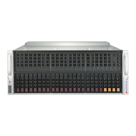
Protogate Freeway 3414 Owner's manual

Protogate, Inc.
12225 World Trade Drive, Suite R
San Diego, CA 92128
Freeway®3414/3414R
Hardware Maintenance
Guide
DC 900-2031A
September 2019

Protogate, Inc.
12225 World Trade Drive, Suite R
San Diego, CA 92128
(858) 451-0865
Freeway 3414/3414R Hardware Maintenance Guide
© 2019 Protogate, Inc. All rights reserved
Printed in the United States of America
This document can change without notice. Protogate, Inc. accepts no liability for any errors this
document might contain.
Copyright notice: Portions of this document are taken from manuals copyrighted December
2005 by Advantech Co., Ltd. and used with permission.
Freeway® is a registered trademark of Protogate, Inc.
Intel®, Pentium® 4, and Celeron® are trademarks of Intel Corporation.
All other trademarks and trade names are the properties of their respective holders.

DC 900-2031A 3
Contents
List of Figures 7
List of Tables 9
Preface 11
Safety Precautions 15
1 Introduction 17
1.1 Maintenance Philosophy. . . . . . . . . . . . . . . . . . . . . . . . . . 18
1.2 Preventative Maintenance . . . . . . . . . . . . . . . . . . . . . . . . . 19
1.3 Freeway Overview. . . . . . . . . . . . . . . . . . . . . . . . . . . . . 19
1.4 Hardware Overview . . . . . . . . . . . . . . . . . . . . . . . . . . . . 21
1.5 Major Functional Features and Components . . . . . . . . . . . . . . . 21
1.6 Multi-Processor Architecture . . . . . . . . . . . . . . . . . . . . . . . 22
1.7 CPU Board. . . . . . . . . . . . . . . . . . . . . . . . . . . . . . . . . 22
1.7.1 CPU . . . . . . . . . . . . . . . . . . . . . . . . . . . . . . . . . . 22
1.7.2 PCI/PCIe Bus Interface . . . . . . . . . . . . . . . . . . . . . . . . 23
1.7.3 LAN Interface . . . . . . . . . . . . . . . . . . . . . . . . . . . . . 23
1.7.4 Serial I/O . . . . . . . . . . . . . . . . . . . . . . . . . . . . . . . . 23
1.8 WAN Processors (ICP Boards) . . . . . . . . . . . . . . . . . . . . . . 23
1.9 Freeway Cabinet . . . . . . . . . . . . . . . . . . . . . . . . . . . . . . 24
1.10 Front Panel. . . . . . . . . . . . . . . . . . . . . . . . . . . . . . . . . 25
1.11 Back Panel . . . . . . . . . . . . . . . . . . . . . . . . . . . . . . . . . 26
2 Maintaining the Freeway Cabinet 27
2.1 Shutdown and Startup Procedures. . . . . . . . . . . . . . . . . . . . . 28

4DC 900-2031A
Freeway 3414/3414R Hardware Maintenance Guide
2.1.1 Preparing for Shutdown . . . . . . . . . . . . . . . . . . . . . . . . 28
2.1.2 Shutdown Procedure (Standard Freeway) . . . . . . . . . . . . . . . 28
2.1.3 Shutdown Procedure (Freeway with SRA). . . . . . . . . . . . . . . 29
2.1.4 Startup Procedure. . . . . . . . . . . . . . . . . . . . . . . . . . . . 29
2.2 Anti-Static Precautions. . . . . . . . . . . . . . . . . . . . . . . . . . . 31
2.3 Opening the Top Cover . . . . . . . . . . . . . . . . . . . . . . . . . . 32
2.4 Replacing the Cooling Fans . . . . . . . . . . . . . . . . . . . . . . . . 33
2.5 Maintaining the Fan Filters . . . . . . . . . . . . . . . . . . . . . . . . 36
3 System Indicators and Power Supply 37
3.1 LED Indicators. . . . . . . . . . . . . . . . . . . . . . . . . . . . . . . 38
3.1.1 System Status LEDs . . . . . . . . . . . . . . . . . . . . . . . . . . 38
3.1.2 Power Status LEDs . . . . . . . . . . . . . . . . . . . . . . . . . . . 39
3.2 Replacing a Power Supply . . . . . . . . . . . . . . . . . . . . . . . . . 41
4 Replacing Freeway Components 43
4.1 Freeway Hardware Configuration . . . . . . . . . . . . . . . . . . . . . 44
4.1.1 Front View . . . . . . . . . . . . . . . . . . . . . . . . . . . . . . . 44
4.1.2 Rear View. . . . . . . . . . . . . . . . . . . . . . . . . . . . . . . . 44
4.2 Replacing a Disk Drive . . . . . . . . . . . . . . . . . . . . . . . . . . 46
4.3 Replacing a CD/DVD drive . . . . . . . . . . . . . . . . . . . . . . . . 48
4.4 Replacing an ICP Board . . . . . . . . . . . . . . . . . . . . . . . . . . 50
4.5 Replacing a CPU CMOS Battery . . . . . . . . . . . . . . . . . . . . . 52
5 Installing New Components 55
5.1 Installing a New ICP Board . . . . . . . . . . . . . . . . . . . . . . . . 55
5.1.1 Installing the Hardware. . . . . . . . . . . . . . . . . . . . . . . . . 55
5.1.2 Updating the bootcfg file . . . . . . . . . . . . . . . . . . . . . . . . 57
5.2 Installing an Additional Ethernet Board . . . . . . . . . . . . . . . . . . 61
5.2.1 Installing the Hardware. . . . . . . . . . . . . . . . . . . . . . . . . 61
5.2.2 Updating the bootcfg file . . . . . . . . . . . . . . . . . . . . . . . . 62

DC 900-2031A 7
List of Figures
Figure 1–1: Freeway Configuration . . . . . . . . . . . . . . . . . . . . . . . . . . . 20
Figure 1–2: Front View of the Freeway 3414/3414R (access door not shown) . . . . 25
Figure 1–3: Example Back View: Freeway 3414 . . . . . . . . . . . . . . . . . . . . 26
Figure 1–4: Example Back View: Freeway 3414R . . . . . . . . . . . . . . . . . . . 26
Figure 2–1: Freeway Power Switch (front) . . . . . . . . . . . . . . . . . . . . . . . 29
Figure 2–2: Freeway 3414 with top cover open. . . . . . . . . . . . . . . . . . . . . 32
Figure 2–3: Fan Tray and Power Connectors . . . . . . . . . . . . . . . . . . . . . . 33
Figure 2–4: Fan Tray Thumb Screw. . . . . . . . . . . . . . . . . . . . . . . . . . . 34
Figure 2–5: Fan Tray Assembly . . . . . . . . . . . . . . . . . . . . . . . . . . . . . 35
Figure 2–6: Fan Filters . . . . . . . . . . . . . . . . . . . . . . . . . . . . . . . . . 36
Figure 3–1: LED Indicators . . . . . . . . . . . . . . . . . . . . . . . . . . . . . . . 38
Figure 3–2: Removable Power Supply . . . . . . . . . . . . . . . . . . . . . . . . . 42
Figure 4–1: Freeway 3414/3414R Front View . . . . . . . . . . . . . . . . . . . . . 44
Figure 4–2: Freeway 3414R Rear View . . . . . . . . . . . . . . . . . . . . . . . . . 45
Figure 4–3: Disk Drive Tray. . . . . . . . . . . . . . . . . . . . . . . . . . . . . . . 46
Figure 4–4: CD/DVD Drive Bay . . . . . . . . . . . . . . . . . . . . . . . . . . . . 49
Figure 4–5: CPU CMOS Battery . . . . . . . . . . . . . . . . . . . . . . . . . . . . 53
Figure 5–1: Slot Numbering: Freeway 3414/3414R . . . . . . . . . . . . . . . . . . 58

DC 900-2031A 9
List of Tables
Table 3–1: System Status LEDs . . . . . . . . . . . . . . . . . . . . . . . . . . . . 39
Table 3–2: Power Status LEDs. . . . . . . . . . . . . . . . . . . . . . . . . . . . . 40
Table 5–1: Bus Numbers: Freeway 3414/3414R . . . . . . . . . . . . . . . . . . . 59
Table A–1: Power Supply Specifications . . . . . . . . . . . . . . . . . . . . . . . . 66

DC 900-2031A 11
Preface
Purpose of Document
This manual describes the maintenance and repair procedures for Protogate’s Freeway
3414 and Freeway 3414R.
Intended Audience
This manual is intended primarily for qualified field support technicians. System
administrators and system integrators might find it useful as well. It can also serve as a
reference guide for manufacturers who incorporate Freeways into their networking
products.
Required Equipment
You may need a number one Phillips-head screwdriver or a straight-blade screwdriver.
Organization of Document
The “Safety Precautions” section on page 15 describes important safety guidelines that
you should review before starting the installation.
Chapter 1 is an overview of the Freeway hardware.
Chapter 2 explains the startup and shutdown procedures, anti-static precautions, how to
open the Freeway cabinet, and how to replace the fans and fan filters.
Chapter 3 describes the system indicators and power supplies.

12 DC 900-2031A
Freeway 3414/3414R Hardware Maintenance Guide
Chapter 4 describes how to replace an ICP board, disk drive, CDROM drive, or CPU
battery.
Chapter 5 describes how to install a new ICP or Ethernet board.
Appendix A lists the hardware specifications.
Appendix B describes how to pack the Freeway for shipping.
References
Document Conventions
The term “Freeway” refers to both of the Freeway models, 3414 and 3414R.
Revision History
The revision history of the Freeway 3414/3414R Hardware Maintenance Guide, Proto-
gate document DC 900-2031A, is recorded below:
•Freeway 3414 Hardware Installation Guide DC 900-2028
•Freeway User Guide DC 900-1333
Document Revision Release Date Description
DC 900-2031A September 2019 Original release
07/01/99
Ginni:
Reworked
table to show
only released
(or almost
released:
1651 and
1677) docs.
Moved
restricted
docs.

Preface
DC 900-2031A 13
Customer Support
If you are having trouble with any Protogate product, call us at (858) 451-0865 Monday
through Friday between 8 a.m. and 5 p.m. Pacific time.
We are always interested in suggestions for improving our products. You can use the
report form in the back of this manual to send us your recommendations.

DC 900-2031A 15
Safety Precautions
Be sure to take the following safety precautions during installation and maintenance of
the Freeway:
•Observe the warnings and directions printed on the Freeway and its associated
equipment.
•Check the electrical rating label on the Freeway chassis. Be sure that the voltage
of your power source matches this rating.
•The Freeway must be plugged into a grounded, three-wire power outlet. Do not
use an adapter that permits a three-wire electrical cord to be plugged into a two-
wire power outlet.
•Use appropriately rated extension cords or power strips only.
•To ensure proper cooling, always operate the Freeway with its covers in place. Do
not cover or block any of the openings on the Freeway chassis. Do not place the
unit near a heater.
•Do not insert objects through openings in the Freeway chassis. Doing so could
result in a short circuit that might cause a fire or an electric shock.
•Do not modify the Freeway equipment in any way. Protogate, Inc. is not respon-
sible for regulatory compliance of any Freeway that has been modified. Altering
the Freeway enclosure in any way other than the installation of Protogate-pro-
vided options may invalidate Freeway’s safety certifications.
•Always unplug the Freeway AC power cord before removing the top or bottom
covers for servicing.
05/12/98:
Per Jean, I
am leaving
only the
English
version of
this in for
now. I also
changed the
spacing
above and
below
everythingso
it would all
fit on one
page.
08/06/99:
Molly needs
this in a few
hours, so I’m
not trying to
kluge the
1532 safety
for SR.

DC 900-2031A 17
Chapter
1Introduction
This chapter covers the following topics:
•Maintenance Philosophy
•Preventative Maintenance
•Freeway Overview
•Hardware Overview
•Major Functional Features and Components
•Multi-Processor Architecture
•CPU Board
•WAN Processors (ICP Boards)
•Freeway Cabinet
•Front Panel
•Back Panel

18 DC 900-2031A
Freeway 3414/3414R Hardware Maintenance Guide
1.1 Maintenance Philosophy
The Freeway 3414 is designed to be repaired in the field, in a repair depot, or at Proto-
gate’s manufacturing facility. A qualified technician must perform all repairs because
many of the devices inside the Freeway are sensitive to static; also, removing or insert-
ing a printed circuit board must be done very carefully to prevent damage to the con-
nectors and avoid causing incorrect power distribution due to a misaligned board.
Later chapters include basic information that will be needed before performing any
maintenance operation:
•Shutdown and Startup Procedures (Section 2.1 on page 28)
•Anti-Static Precautions (Section 2.2 on page 31)
•Opening the Top Cover (Section 2.3 on page 32)
The following units can be replaced in the field:
•Fan filters (Section 2.5 on page 36)
•Cooling fans (Section 2.4 on page 33)
•Hard or flash drive (Chapter 4.2 on page 46)
•CPU CMOS Battery(Section 4.5 on page 52)
•ICP board (Section 4.4 on page 50)
The following units can be added in the field:
•ICP board (Section 5.1 on page 55)
•Ethernet board (Section 5.2 on page 61)

1: Introduction
DC 900-2031A 19
Protogate does not recommend replacing the CPU board or single power supply (3414
only) in the field, therefore they are not documented in this manual. Replacing the CPU
board requires multiple cable connections and specific BIOS settings. To replace the
single power supply, you must remove most of the internal components. Because of this
complexity, it is recommended that these two items be replaced only at the repair depot
or at the Protogate factory.
1.2 Preventative Maintenance
The following are the recommended preventative maintenance actions for the Freeway:
1. Check and clean the fan filter every three months as described in Section 2.4 on
page 33.
2. Replace the CPU CMOS battery every 5 to 10 years as described in Section 4.5
on page 52.
1.3 Freeway Overview
The Freeway enables client applications to access specialized wide-area networks
(WANs). It is user programmable and communicates in real time. It provides multiple
data links and a variety of network services to LAN-based clients in financial, defense,
telecommunications, and process-control applications. To maintain high data through-
put, the Freeway uses a multi-processor architecture to support the LAN and WAN ser-
vices. Figure 1–1 shows a block diagram of the Freeway configuration in a typical
application.
The LAN interface is managed by the server processor (on the CPU board).This single-
board computer uses the FreeBSD operating system to provide layered services needed
by the Freeway.
The WAN interface is managed by one or more intelligent communications processors
(ICPs). These boards communicate with the CPU board through a Peripheral Compo-

20 DC 900-2031A
Freeway 3414/3414R Hardware Maintenance Guide
nent Interconnect (PCI) bus and use Protogate’s OS/Protogate real-time operating sys-
tem to run the protocol software.
Figure 1–1: Freeway Configuration
Freeway
3027
ICPs
ICP Device Driver
TSI
TCP/IP Socket Interface
TSI
MSGMUX
Ethernet (LAN)
Client Application
DLI
Client
TCP/IP Socket Interface
Serial Lines (WAN)
This manual suits for next models
1
Table of contents
Other Protogate Server manuals


