Providence STV-1JB User manual

SYSTEM TUNER
STV-1JB
OWNER’S MANUAL
Handcrafted in JAPAN
TOTAL ROUTING SYSTEM with TUNER

Thank you for choosing a Providence product. In order to take full advantage of the
features and performance the product provides, please read this owner’s manual
thoroughly, and keep it in a safe place for future reference.
■Main Features
●Overall Routing & Junction Box Functions
With its IN/OUT and SND/RTN connectors, the STV-1JB System Tuner can
function as a routing system that provides overall pedal system muting while
tuning. It can also function as a junction box and splitter.
(a) Splitter
The STV-1JB functions as an active splitter when the built-in VITALIZER circuit is
turned ON and output is taken in parallel from the SND and OUT connectors. This is
ideal when you want to use two amplifiers simultaneously, when you need a dry
signal in addition to the “wet” signal to which effects have been added, when you
want to send a signal to an amplifier and mixing console at the same time, and more.
(b) Easy-to-use Layout
The connector layout has been specifically designed for maximum space efficiency
and ease-of-use when the STV-1JB is used in a pedal board.
●VITALIZER
The Providence VITALIZER has become an indispensable part of many professional
pedal board systems. It is an active impedance converter that prevents
degradation of the instrument signal and makes it more resistant to noise even after
passing through multiple jacks, contact points, and cables, all while retaining the
instrument’s natural tone. A VZ THRU switch allows the VITALIZER circuit to be
bypassed in situations where a fully passive true-bypass signal path is required.
●Overall Mute for Series-connected Pedal Systems
Because tuners are normally placed first in a pedal chain, their mute function
mutes the signal before it is sent to subsequent pedals. When a pedal system is
connected to the STV-1JB SND/RTN loop the tuner becomes the first component
in the pedal chain, as usual, but muting occurs right at the end the pedal chain to
completely shut off any residual noise or spurious reverb signals when not actually
playing.
●Ultra-precise, High-visibility KORG Pitchblack Advance Tuner Built In
When the footswitch is pressed to activate the tuner, the audio signal is muted so
that tuning can be carried out without sending any signal or noise to the amplifier.
When the tuner is switched off, the tuner and signal circuits are completely isolated
by a relay switch so that digital noise cannot affect the audio signal.
●DC9 ~ 18V Power Supply Output
The power supply connected to the DC IN jack can be supplied to a second
device or multiple devices via the DC OUT jack. The DC IN supply voltage range is
from 9V to 18V, and the same voltage is available at the DC OUT jack. If a fault or
short occurs in any cable or device connected to the DC OUT jack, an internal
overcurrent protection circuit will prevent damage to the AC adapter or other
external power supply used. The overcurrent protection circuit recovers
automatically when the fault has been corrected.
●006P Battery Power
As an alternative to external power, the STV-1JB can be powered from an internal
006P 9V battery that also retains tuner calibration and mode settings.

①
TUNER ON/OFF
:
This switch turns the tuner ON and OFF. The OUT signal is muted
when the tuner is turned ON.
②TUNER ON/OFF LED
:
This LED indicates whether the tuner is ON or OFF. The LED
lights red when the tuner is ON. The TUNER ON/OFF LED also indicates remaining
battery power by flashing when the battery voltage falls below 6 volts. Replace the
battery as soon as possible when the LED begins to flash.
③
LED Tuning Meter
:
These LEDs light in flowing patterns that facilitate precise tuning.
(refer to“Tuning” for details)
④
Tuning Guide LEDs
:
The left tuning guide LED lights when the pitch is too low, and
the right tuning guide LED lights when the pitch is too high. Both tuning guide LEDs
light when the pitch is correct.
①
⑦
⑧
⑨⑩
⑪
⑫
⑬
⑭
■Controls and Functions
③④
④
⑤
⑥
②

⑤
Note Display
:
When a single note is input, the name of the nearest note is displayed here.
⑥
DC IN Jack
:
An external power supply (AC adapter) connects here. The STV-1JB
accepts input voltages from 9V DC to 18V DC. Use a voltage regulated power supply
with a center-negative ( ) plug.
⑦
IN Jack
:
This is the audio input jack. Connect your guitar or bass here.
⑧
VZ THRU Switch
:
This switch determines whether the internal VITALIZER circuit is
inserted into the signal path or bypassed. Set the switch to “VZ” to insert the VITALIZER
into the signal path. When set to “THRU” the VITALIZER circuit is bypassed and the unit’s
true bypass circuit is engaged so that the IN signal is connected directly to the OUT jack.
⑨
OUT Jack
:
The OUT (output) jack
connects to the input of your amplifier, mixer, or
similar device. The STV-1JB mute circuit is located immediately before the OUT jack so
that muting always occurs after any effects connected between the SND (send) and
RTN (return) jacks, completely shutting off any residual noise while tuning.
⑩
RTN Jack
:
The RTN (return) jack receives the output from any effect units fed by the
unit’s SND (send) jack.
⑪
DISP Switch
:
The DISP switch is used to change tuner display modes.
(
refer to
“Tuning” -> “Display Modes” for details)
⑫
CALIB Switch
:
The CALIB switch is used to calibrate the tuner.
(
refer to
“Tuning” -> “Calibration” for details)
⑬
SND Jack
:
The SND (send) jack connects to the input of the first or only effect unit in
an effect chain to be connected into the STV-1JB SND/RTN loop.
⑭
DC OUT Jack
:
The voltage from a power supply connected to the DC IN jack is
output via this jack. The DC OUT jack ( ) can be connected to the power input
jack of a separate effect unit. The voltage input at the DC IN jack (9V ~ 18V DC) is
output via the DC OUT jack without modification, so it is important to check the power
input specifications of any secondary device(s) being powered via this jack.
*The DC OUT jack cannot be used to power a second device when the STV-1JB is
being powered by an internal battery.
CAUTION!
The output voltage from the DC OUT jack cannot be adjusted. The voltage from an external AC
adapter/power supply connected to the DC IN jack is output via the DC OUT jack unchanged. Be sure to
use a power supply that is suitable for any external effect units that are to be powered from the STV-1JB
DC OUT jack. The maximum total power output capacity of the STV-1JB DC OUT jack is 1.5 amps. Be
sure not to exceed this value.
When the DC OUT jack is to be used to power external devices, the AC adapter/power supply
connected to the DC IN jack should have a power output capacity that is approximately twice the total
power consumption of the device(s) to be powered.
Example: If the total power consumption of all devices to be powered is 500mA (500 milliamps), an AC
adapter/power supply that can deliver 1A (1 amp) should be used. The STV-1JB DC OUT circuit features
overcurrent protection*2 that will prevent damage to the connected AC adapter/power supply if a short
or other fault occurs in a cable or device connected to the DC OUT jack. The overcurrent protection
circuit will recover automatically when the fault is corrected.
*2 The overcurrent protection circuit is activated when a continuous output current of greater than 1.5
amps is detected.
About the VITALIZER
The Providence VITALIZER circuit is an active low-impedance converter that makes audio
signals more resistant to noise and prevents signal degradation that can occur when audio
passes through cables and switch contacts. The VITALIZER circuit is most effective when used
with instruments that have passive pickups, but it can help reject spurious noise with active
pickups as well.

■Tuning procedure
1. Press the TUNER ON/OFF switch to activate the tuner.
The TUNER ON/OFF LED will light. Because STV-1JB has a Muting circuit,
you can only tune silently, meaning you will not hear your audio signal
through an amp etc.
2. If desired, adjust the calibration and/or select the display mode.
STV-1JB comes from the factory with the calibration set to A=440 and
the tuning mode set to Meter (see “Adjusting the calibration” &
“Choosing a display mode”).
3. Play a single note on your instrument and tune it so that the desired
note appears in the note name display.
The note name closest to the entered note appears in the note name
display.
4. Tune your instrument using the tuning LED meter.
The method for indicating whether your instrument is in tune, sharp or flat
depends on which display mode you choose. (see “Choosing a display
mode”)
5. After you finish tuning your instrument, press the TUNER ON/OFF
switch to turn the tuner off.
The TUNER ON/OFF LED turns off. Now your signal will be heard through
your amp.
■Adjusting the calibration
STV-1JB comes from the factory with the calibration set to A=440 Hz. If an
adjustment is necessary, you can do so within a range of 436–445 Hz.
1. Press the CALIB button.
The current calibration setting will blink for several seconds in the note
name display (Light →Blink).
2. While the current calibration setting is shown in the note name
display, press the CALIB button again to adjust the setting.
Each time you press the CALIB button you will cycle through the following
settings.
0: 440Hz, 1: 441Hz, 2: 442Hz, 3: 443Hz, 4: 444Hz, 5: 445Hz, 6: 436Hz,
7: 437Hz, 8: 43 Hz, 9: 439Hz
3. After you have selected your desired calibration setting, wait
approximately two seconds without pressing any buttons.
The new setting will blink in the note name display indicating the calibration
has been set. STV-1JB will automatically return to tuner mode.
■Choosing a display mode
STV-1JB allows you to choose one of four display mode settings. The
factory setting is Regular mode.
1. Press the CALIB button.
The current calibration setting will blink for several seconds in the note
name display (Light →Blink).
2. While the current calibration setting is shown in the note name
display, press the CALIB button again to adjust the setting.
Each time you press the CALIB button you will cycle through the following
settings.
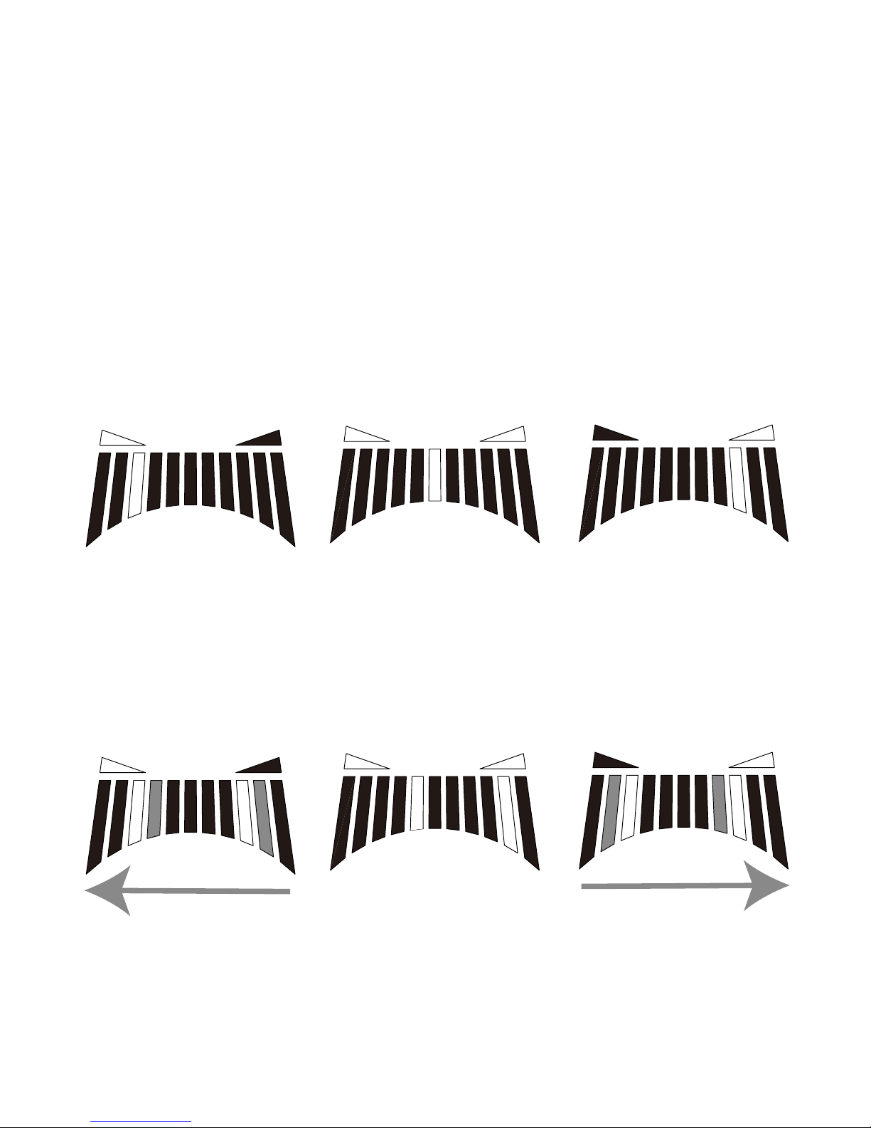
1: Regular
Tune your instrument until the LED at the center of the LED meter is lit. An
LED on the right will light up if the pitch is high, and an LED on the left will
light up if the pitch is low.
The pitch
is low.
In tune. The pitch
is high.
The pitch
is low.
In tune. The pitch
is high.
2: Strobe
Tune your instrument until the LEDs stop running. Since the strobe meter
has a higher precision, it allows you to tune with greater accuracy. The
LEDs light up,
running from left to right if the pitch is high and from right to left if the pitch
is low.
The display mode setting will be remembered even if the power is
turned off. However, this setting will be reset to the factory default
(Regular) if the battery is removed. In addition, this setting will be reset
to the factory default if an adapter not connected to an AC outlet is
plugged into the tuner, even if the battery is installed.
The pitch
is low.
In tune. The pitch
is high.
The pitch
is low.
In tune. The pitch
is high.
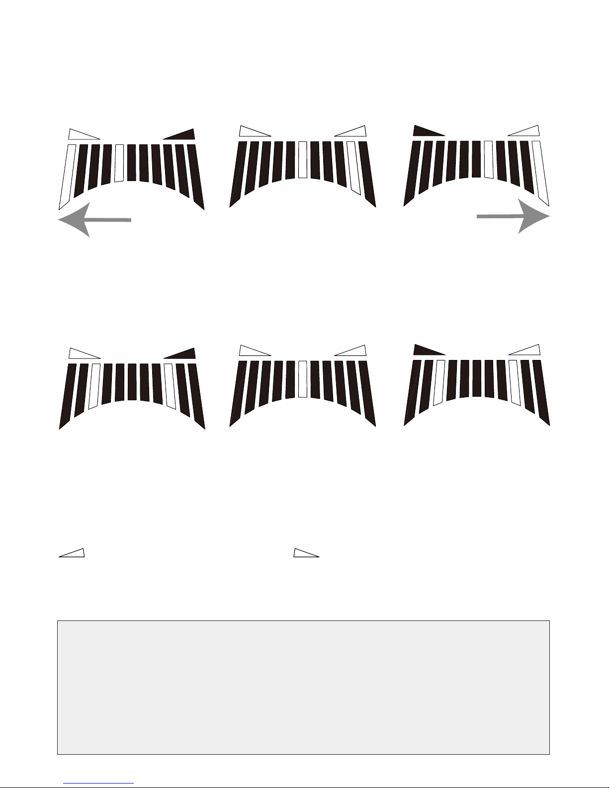
3: Half-strobe
Tune your instrument until the LEDs stop running and only the center LED is
lit. The LEDs on the right will strobe if the pitch is high, and the LEDs on the
left will strobe if the pitch is low. When the pitch is in tune, only the center
LED is lit.
4: Mirror
Tune your instrument so that the two illuminated LEDs in the left and right
side of the LED meter coincide in the center. The farther your instrument is
from the correct pitch, the farther apart the illuminated LEDs will be.
3. After you’ve chosen the display mode you would like to use, wait
approximately two seconds without pressing any buttons.
The note name display will blink, the display mode will be set, and STV-1JB
will automatically return to tuner mode. With all display modes, the tuning
guide LEDs indicate whether the pitch is high or low.
will light up if the pitch is high, will light up if the pitch is low, and
both will light up when the pitch is in tune.

■EX.1 (Signal Junction Box)
Using with several effect pedals
■EX.5 (Signal splitter)
2 Tracks through audio interface
OUTPUT GAIN
BASS TREBLE
IN
OUT
LEVEL DRIVE
TONE

■EX.2 (Signal Junction Box)
Using with Routing system
■EX.6 (Signal splitter)
Signal to amp and another to
mixer through DI
OUTPUT GAIN
BASS TREBLE
IN
OUT
LEVEL DRIVE
TONE
IN
OUT
LEVEL DRIVE
TONE
OUT IN EXT.TAP
BPM
mSec
A/B
TAP
MIX ECHO HARDNESS FEED BACK TIME
BEAT SPLIT
ON/OFF A/B
TAP
3
3
D.I.
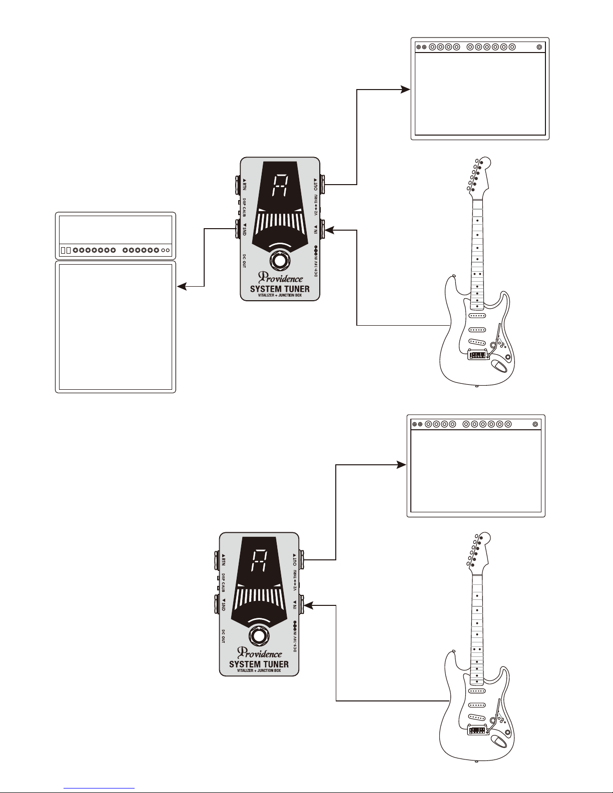
■EX.3 (Signal splitter)
Using two amps
■As a Tuner

■EX.4 (Signal splitter)
Using two amps with DRY and WET
IN
OUT
LEVEL DRIVE
TONE
OUT IN EXT.TAP
BPM
mSec
A/B
TAP
MIX ECHO HARDNESS FEED BACK TIME
BEAT SPLIT
ON/OFF A/B
TAP
3
3
■Using DC OUT
Supply power to other devices
from DC OUT
IN
OUT
LEVEL DRIVE
TONE
ACadapter
(DC9V〜18V) OR
*Powerconsumption
mustbelessthen1.5A
intotal. Powersupply
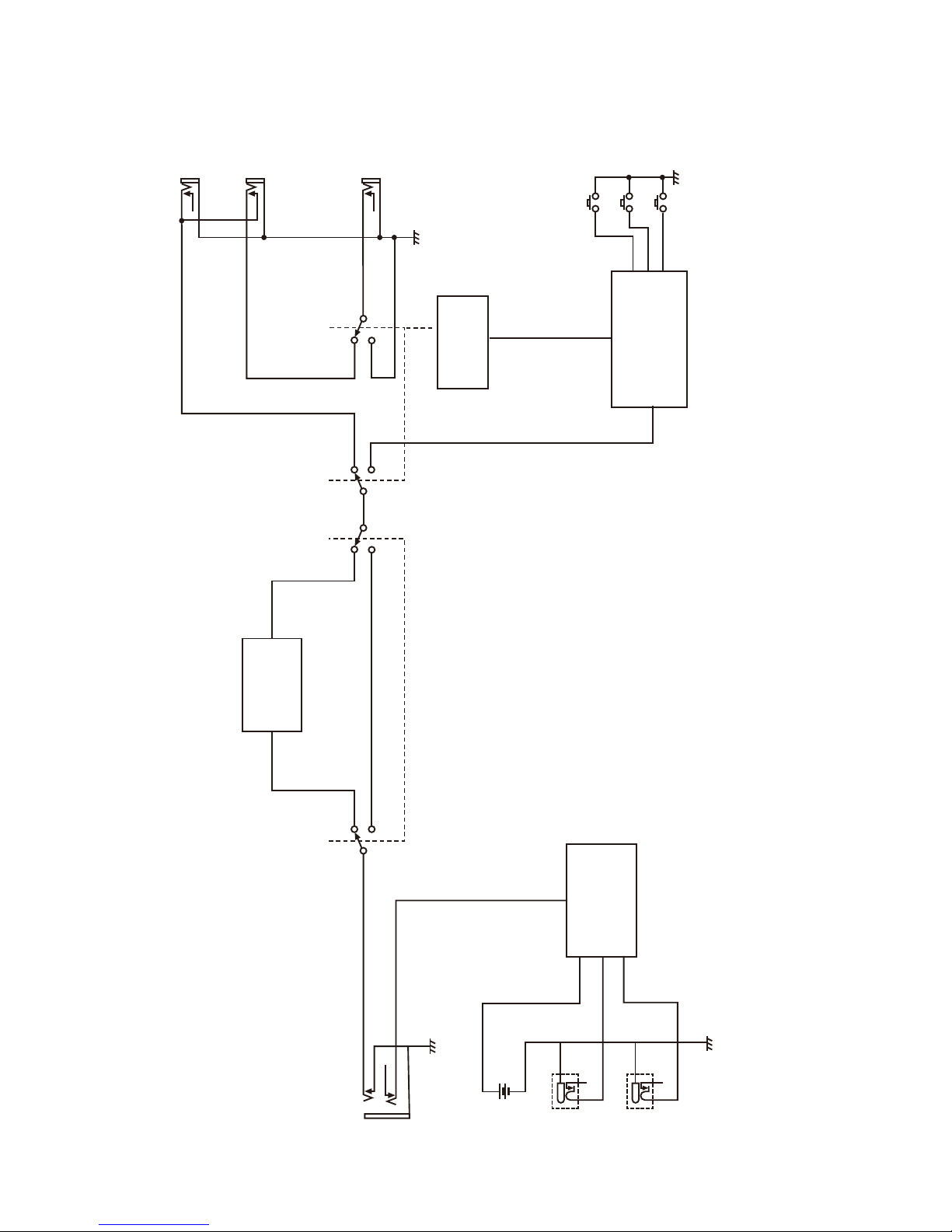
■Block Diagram
IN
BATT 9V
DC OUT
POWER SUPPLY
CIRCUIT
TUNER ON/OFF
(F.SW)
SEND
RETURN
OUT
CALIB
DISPLAY
TUNER UNIT
VITALIZER
RELAY
DC IN
9-18V

■Specifications
●VITALIZER
Input impedance: 1 MΩ
Output impedance: 100 Ω or less
●Jacks
IN, OUT, SEND, RETURN, DC IN, DC OUT
●Controls
Tuner: CALIB (tact switch), DISPLAY (tact switch)
Signal:
VITALIZER ⇔ THRU (slide switch), TUNER ON / OFF (foot switch)
●TUNER (KORG Pitchblack Advance)
Scale: 12-note equal temperament
Detection range: E0 (20.60 Hz)–C8 (4186 Hz)
Calibration range: A4 = 436–445 Hz (1 Hz steps)
Detection accuracy: +/-0.1 cent
●Power
9V battery (1 piece), DC 9 ~ 18V, AC adapter (Not included)
●Power consumption
Maximum 27 mA (when using AC adapter)
Maximum 12 mA (when using 9 V battery)
●Battery life
Tuner on, continuous 30 hours
(Using 9 V manganese battery, A4 continuous input, display mode: regular)
Tuner on, continuous 60 hours
(Using 9 V alkaline battery, A4 continuous input, display mode: regular)
●Size
115 (D) x 76 (W) x 50 (H) mm
●Weight
Approximately 220g (without batter)
■Battery Replacement & Calibration/Display Mode Settings
Calibration and display mode settings are reset to their default values
when the internal battery is disconnected for replacement.*
* The calibration and display mode settings can be retained during bat-
tery replacement if a cable is plugged into the IN jack and an AC adapt-
er/power supply is connected to the DC IN jack to maintain power to the
unit while the battery is disconnected.
●Never open the case to modify or take apart the product.
●No user serviceable parts inside. Contact the store you purchased or authorized
distributor in your area if you have trouble with your apparatus.
●Be sure to use the proper AC Adapter depending on the voltage system in your
country/area. Refer to the product manual for specific required voltage and
current draw information. Never unplug or plug the AC adapter when your
hands are wet.
●Do not excessively bend the power cord or leave heavy objects on top of it.
Damaging the power cable could cause fire, electronic shock, and / or short
circuit.
●In the following circumstances, turn off the apparatus and unplug the AC
Adapter immediately, and contact the store the item was purchased at or
authorized distributor in your area to place a repair order.
○The power supply cord or the plug is damaged.
○Liquid is has been spilled or objects have fallen into the apparatus.
○The apparatus has been exposed to rain or extreme moisture.
○The apparatus does not operate normally or changes in performance happens
in a significant way.
●Do not use or keep the apparatus in the following places.
○Places where there is excessive heat such as radiators, heat registers, stoves,
or other apparatus that produce extreme heat.
○Places the apparatus is exposed to direct sunlight.
○Places near water or high humidity such as a bathtub, washstand, wet floor, etc.
○Places surrounded by dust.
○Places that will vibrate the apparatus a lot.
Safety Information
Warning:
Warning:
Caution:
Please be sure to read this manual and follow the instruction before
using this product in order to insure safe operation of the product.
This symbol indicates an item that can result in
death or serious personal injury if ignored.
This symbol indicates an item that can result in
serious personal injury or material damage if
ignored.
The following precaution symbols alert you and others to the risk of personal
and material injury that may be caused if the precaution is ignored.

■Notes about replacing the battery:
●When replacing a battery, do not pull the snap cord too hard.
●When closing and screwing the back cover of the pedal, make sure the snap
cord is placed inside of the box and does not get caught in the back cover.
Closing the back cover with the snap cord caught will cause snapping of a wire
or shorting the power circuit. Please be careful.
■Notes about the product with external power
input jack (AC adapter jack):
●We highly recommend you to keep the battery in the pedal in case the AC
adapter plug is accidentally disconnected, the power circuit will automatically
switch to the battery and you can keep playing it.
If you have to run it with external power (AC adapter) only, please cover the
battery snap's polarities with electrical tape in order to avoid touching it to the
circuit and chassis. Please be careful that polarities are not touching the circuit
as this could cause the product to breakdown.
●Unplug this apparatus during lightning storms or when unused for long periods
of time to reduce the risk of fire.
●Be sure the battery is firmly connected to battery snap with the correct
polarities.
●Remove the battery if the apparatus is not used for a long period of time.
●Do not drop the apparatus or step on it to give extreme stress and shock.
●Do not step on the switch with barefoot. It may cause an unexpected injury.
●Do not use solvents such as paint thinner or benzine to clean the apparatus.
Clean your apparatus with a damp cloth only.
Caution:

Follow us!
https://www.instagram.com/providence.jp/
https://www.facebook.com/ProvidenceLTD
https://twitter.com/providence_jp
3-21-7, Tsurumi-Chuo, Tsurumi-ku Yokohama-shi, Japan 230-0051
TEL. +81-45-510-4060 FAX, +81-45-510-4061
E-mail: overseas1@pacifix-ltd.com
http://www.providence-ltd.com
Table of contents
Other Providence Tuner manuals


