— 4 —
4. Release ENTER and RETURN . The KEY CHECK mode will be set.
5. All key numbers will be displayed.
Key Number : 12
6. Each time the key is pressed, the key number will be counted down.
Each key will be counted only once, at the first time.
7. When all keys have been pressed, the process will end.
NOTE : As contents of the Factory Preset will be written into memory after completing this check mode, delete contents of memory
according to 4. Forced RESET.
3. Entering the Factory Preset (In case perform just to write memory of the Factory Preset.)
1. Turn OFF the power.
2. While pressing ENTER and MEMORY together, turn ON the power.
4. Forced RESET (Used to delete the contents of Factory Preset when it is written into the preset memory.)
Clears all the RAMs and sets the initial state
1. Turn OFF the power.
2. While pressing ENTER and ANTENNA together, turn ON the power.
3. When “All clear” is indicated on the display tube.
SECTION 3
ELECTRICAL ADJUSTMENTS
Precautions in Repairing
If the front end unit fails, it is difficult to repair the inner circuits, so
replace the entire front end unit.
Set “IF : WIDE” after the all adjustments.
FM SECTION 0dB = 1µV
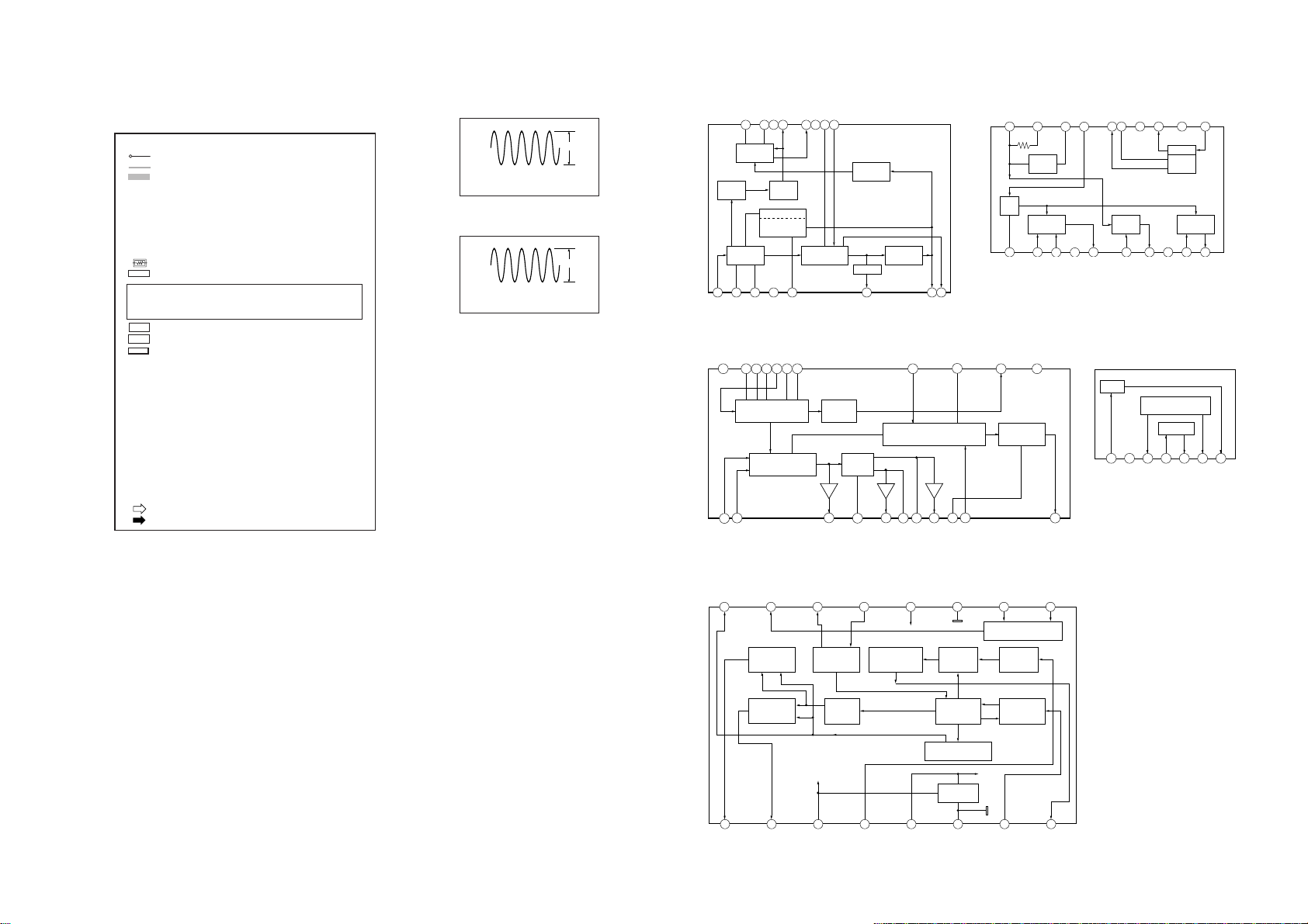
• Standard Setting of FM Stereo RF Signal Generator.
STEREO STANDARD SIGNAL MONAURAL
STANDARD SIGNAL
Carrier frequency : 98MHz
Modulation : Audio 1kHz
Main channel (L+R) :33.75kHz
deviation
Sub channel (L–R) :33.75kHz
deviation
Pilot :7.5kHz
deviation
Carrier frequency : 98MHz
Modulation : Audio 1kHz
75kHz deviation
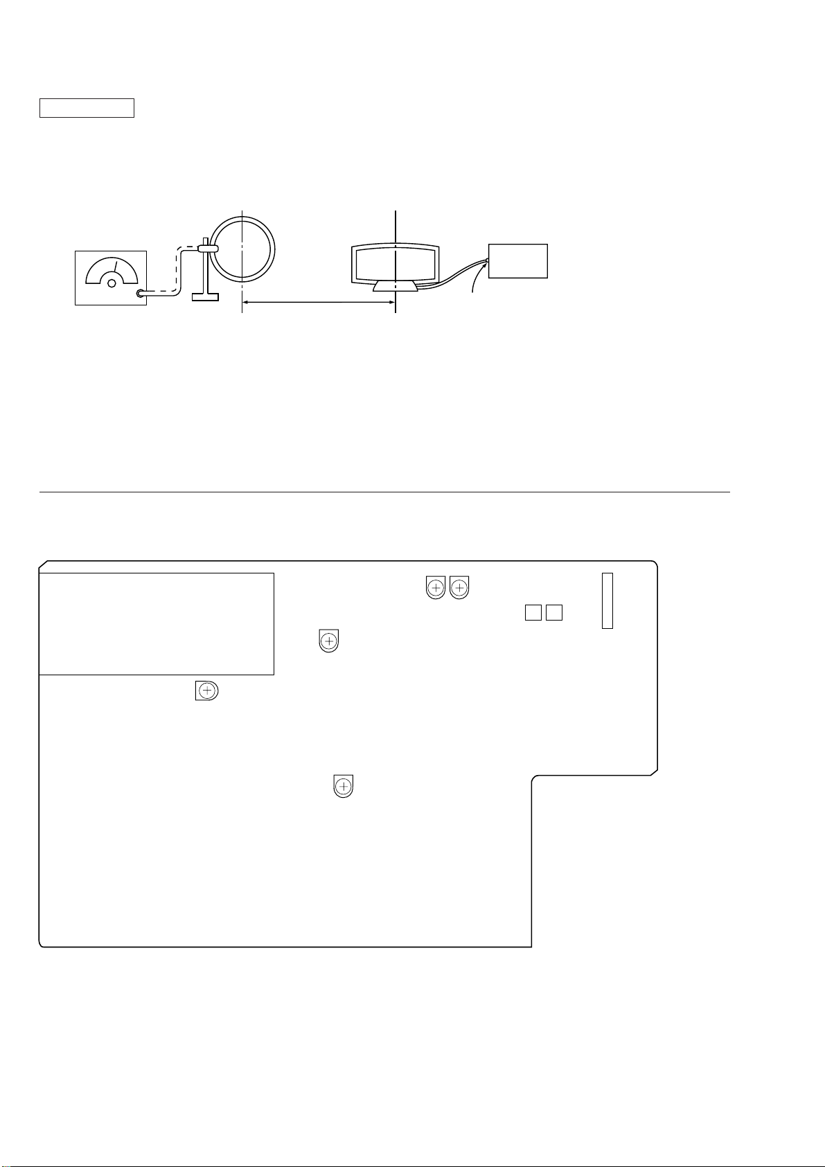
FM RF SSG 1 kHz
highpass
filter distortion meter
FM ANTENNA (75
Ω
)LINE OUT
set
How to switch IF BAND : WIDE/NARROW and ANT ATT :
ON/OFF
Method:
1. Press the power button to turn the power on and set to FM.
2. Press the MENU button and press the TUNING/SELECT –, +
button to indicate “Reception” on the fluorescent display tube,
then press the ENTER button.
3. Press the TUNING/SELECT –, + button to indicate “ATT/IF
Band”, and press the ENTER button.
4. “ANT ATT: OFF” is indicated on the fluorescent display tube
and press the TUNING/SELECT –, + button to indicate “ON”
or “OFF”, then press the ENTER button.
When theANTATT is set, “ANTATT” is indicated on the fluo-
rescent display tube.
5. “IF:Wide” is indicated on the fluorescent display tube, and press
the TUNING/SELECT –, + button to indicate “Wide” or “Nar-
row”, then press the ENTER button.
When the “IF: Narrow” is set, “NARROW” is indicated on the
fluorescent display tube.
6. Set WIDE after the operation.