Proview HV205 User manual

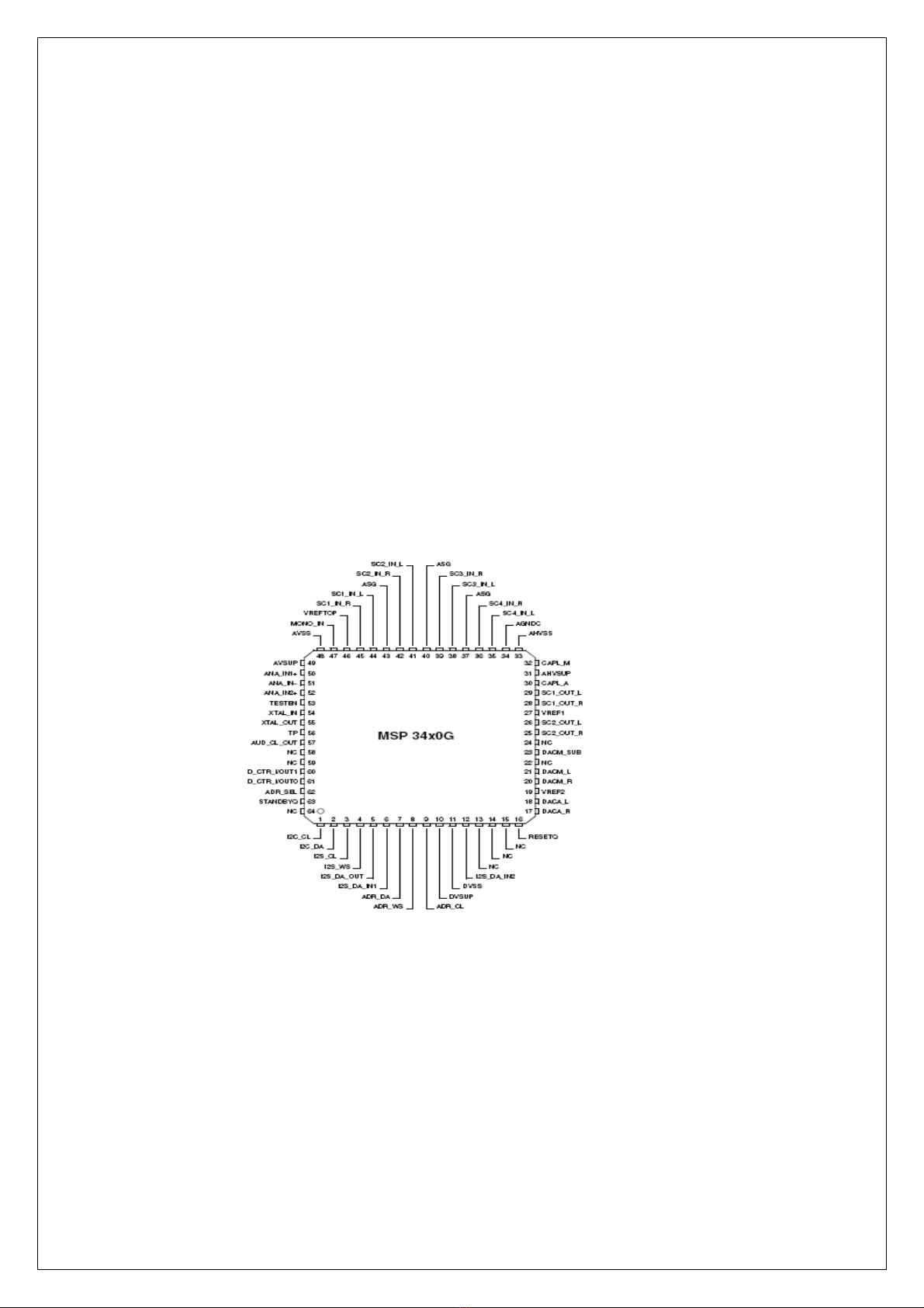
HV205
Service Manual

TABLE OF CONTENTS
1. Precautions and Safety Notices………………………………………………………….3
2. Specification…………………………………………………………………………………4
3. Function Control Description……………………………………………………………..8
4. Circuit Description…………………………………………………………………………14
5. Adjusting Procedure………………………………………………………………………19
6. Trouble Shooting Flow Chart……………………………............................................20
7. Spare Parts List……………………………………………………………………………..24
8. Recommended Spare Parts List………………………….………………………………28
9. Exploded Diagram and Spare Parts List……………………………………………….29
10.Block Diagrams……………………………………………………………………………..31
11.Schematic Diagrams……………………………………………………………………….32
12.PCB Layout Diagrams……………………………………………………………………...44

1. Precautions and Safety Notices
Prior to using this service manual,please ensure that you have carefully followed all the procedures outlined in
the user's manual for this product.
(1) Read all of these instructions.
(2) Save these instructions.
(3) Follow all warnings and instructions marked on the product.
(4) Unplug this product from the wall outlet before cleaning.Do not use liquid cleaner or aerosol
cleaner, use a damp cloth for cleaning.
(5) Do not use this product near water.
(6) Do not place this product on an unstable cart,stand or table.The product may fall,causing serious
damage to the product.
(7) Slots and openings in the cabinet and the back or bottom are provided for ventilation,to ensure
reliable operation of the product and to protect it from overheating.Those openings must not be
blocked or covered.The openings should never be blocked by placing the product on a bed,sofa, rug,
or other similar surface.This product should not be placed in a built-in installation,since proper
ventilation is provided.
(8) This products should be operated with the type of power source indicated on the marked label.
If you are not sure of the type of power is available, consult with your dealer or local power company.
(9) This product is equipped with a 3-wire grounding type plug,a plug having a third (grounding)
pin.This plug will only fit into a grounding-type power outlet.This is a safety feature.If you are
unable to insert the plug into the outlet,contact your electrician to replace your obsolete outlet.Do
not damage the purpose of the grounding-type plug.
(10)Do not allow anything to rest on the power cord.Do not locate this product where persons will walk
on the cord.
(11)Never push any kinds of objects into this product through cabinet slots as they may touch dangerous
voltage points or short out parts that could result in a risk of fire or electric shock.Never spill any kinds
of liquid on the product.
(12)Do not attempt to service this product yourself,as opening or removing covers may expose you to
dangerous voltage points or other risk.Refer all servicing to service personnel.
(13)Unplug this product from the wall outlet and refer servicing to qualified service personnel under the
following conditions.
a. When the power cord or plug is damaged or frayed.
b. If liquid has been spilled into the product.
c. If the product has been exposed to rain or water.
d. If the product does not operate normally,when the operating instructions are followed.Adjust
only those controls involved in the operating instructions ,since improper adjustment of
other controls may result in damage and will often require extra work by a qualified
technician to restore the product to normal operation.
e. If the product has been dropped or the cabinet has been damaged.
f. If the product exhibits a distinct change in performance,indicating a need for service.
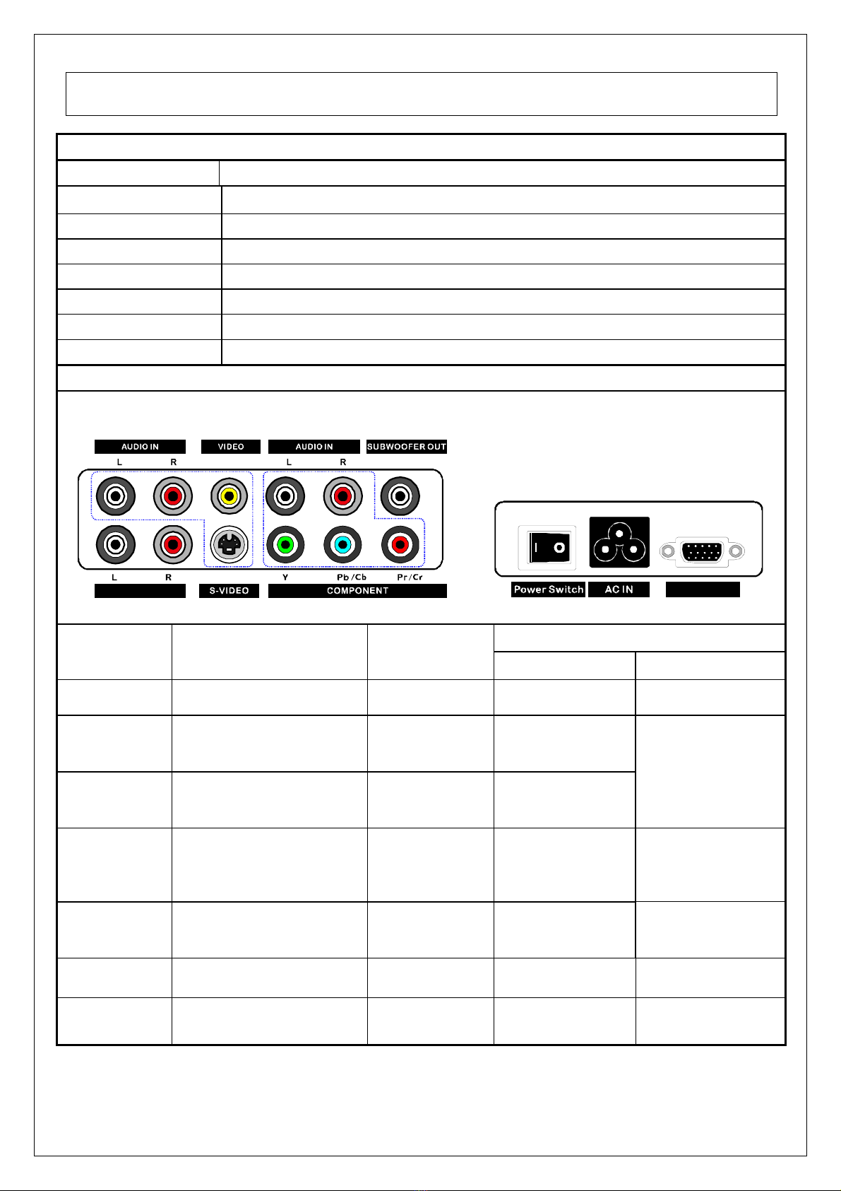
2. Specification
Panel General Specification
MODEL No. HV205
Display Pixel
800 (H) x 600 (V) pixels ( 1 pixel = 1 RGB cells )
Pixel pitch
0.51mm (H) x 0.51mm (V)
Active Display Area
408.0mm (H) x 306.0mm (V)
Number of Colors
16.7M
View Angle
±80°degree(H), ±60°degree (V) Typical
Brightness
350cd/m
2
typical with 16 pieces of CCFL
Contrast
450:1 typical at CR 10
Input Source
Interface Board
VGA LINE IN
VGA
Connector type
Inputs &
Output Signals Video Format Video
TV Main-TV NTSC F / IH Type TV
C-VIDEO Composite
+ L/R Audio CVBS RCA x 1 (Yellow)
S-VIDEO S-Video
+ L/R Audio Y/C Mini Din 4 Pin
RCA x 2 (Red ,
White)
Component YCbCr / YPbPr
+ L/R Audio
480i/480p,
720p, 1080i
RCA x 3
(Red,
Blue ,Green)
RCA x 2
(Red , White)
VGA IN Analog RGB
+ L/R AudioAnalog RGB D-Sub 15 Pin
RCA x 2
(Red , White)
AC IN Inverter AC Power IN AC 110~220V YC14 AC IN
Woofer Out External Subwoofer N/A N/A RCA x 1
(Black)
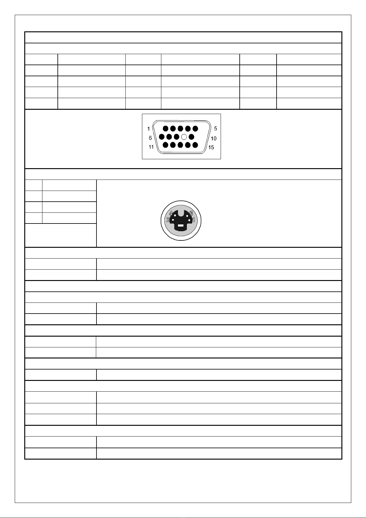
VGA Connector
D-Sub type connector pin assignment
1. Red Video 6. Red Ground 11. GND
2. Green Video 7. Green Ground 12. SD
A
3. Blue Video 8. Blue Ground 13. H-s
y
nc.
4. Gnd. 9. +5V 14. V-s
y
nc.
5. None 10. S
y
nc Gnd 15. SCL
Mini DIN for S-video
1. Ground
2. Ground
3. Y
4. C
4-PIN MINI DIN CONNECTOR
TV broadcasting system input
NTSC For USA or relative areas
PAL/SECAM Optional for Europe or relative areas
Component Video signal
YCbCr / YPbPr for SDTV 480i mode
Y Signal 1Vp-p/75 Ohm
C Signal +/- 350 mV(MAX)/75 Ohm, when input pattern is 100% color bar.
S-Video(Y/C) Signal
Y Signal 1Vp-p/75 Ohm
C Signal +/- 286 mV(MAX)/75 Ohm, when input pattern is 100% color bar.
Video(Composite) CVBS Signal
Single 1Vp-p/75 Ohm, when input pattern is 100% color bar.
Sync Signals
Type Positive and negative sync of Separate Horizontal/Vertical Sync.
Level TTL level HL: 2V – 5V Vpp , LL: 0V – 0.8V Vpp.
Impedance 2 K Ohm minimum
Audio Signals
Input 2 Vrms/47 K Ohm.
Output 2 Vrms/3.3 K Ohm

Signal Timing
NTSC: National Television System Committee.
Basic Parameters NTSC M
line/field 525/60
horizontal frequency 15.734 kHz
vertical frequency 60 Hz
color subcarrier freq. 3.579545 MHz
video bandwidth 6.0 MHz
audio carrier 4.5 MHz (FM)
PAL: Phase Alternation Line.
Basic
Parameters
PAL B-G-H PAL I PAL D PAL N PAL M
line/field 625/50 625/50 625/50 625/50 525/60
horizontal
frequency 15.625 kHz 15.625 kHz 15.625 kHz 15.625 kHz 15.734 kHz
vertical
frequency 50 Hz 50 Hz 50 Hz 50 Hz 60 Hz
color
subcarrier
freq.
4.433618 MHz 4.433618
MHz. 4.433618 MHz. 3.582056
MHz. 3.575611 MHz.
video
bandwidth 5.0 MHz 5.5 MHz. 6.0 MHz. 4.2 MHz. 4.2 MHz.
audio
carrier 5.5 MHz. (FM) 6.0 MHz. 6.5 MHz. 4.5 MHz 4.5 MHz.
SECAM: Sequential Couleur Avec Memoire.
Basic Parameters SECAM B-G-H SECAM D-K-K1-L
line/field 625/50 625/50
horizontal frequency 15.625 kHz. 15.625 kHz.
vertical frequency 50 Hz. 50 Hz.
video bandwidth 5.0 MHz 6.0 MHz.
audio carrier 5.5 MHz (AM) 6.5 MHz (AM)
In general, these subsystems are used for broadcast in
B VHF G UHF H UHF I VHF/UHF
D VHF N VHF/UH
F
M VHF/UHF K UHF
K1 VHF/UHF L VHF/UH
F
Video Inputs
No Resolution H-
Freq.(KHz) V-Freq.(Hz) Pixel clock
(MHz) Proposed
1 640 x 480 15.73 60 13.500 NTSC 525i
2 640 x 480 15.63 50 13.500 PAL 625i
3 960 x 483 31.5 60 18.00 SDTV 480i
MODEL No HV205
Power Source 100-240V~,50/60Hz,70W
Power Consumption 60W Max with speaker Standby : < 5W
Physical 24.5(W) x10.1(D) x18.6(H)(Inch)
622.3(W) x256.54(D) x472.44(H)(mm)
Dimension
(W×H×D)
Carton 27.48 X11.15 X21.46(Inch)
698 X 283 X 545MM
Net 10.2Kg(22.4lbs)
Weight
Gross 12.5Kg(27.5lbs)
Sound Output 5W X2, 8Ohm.
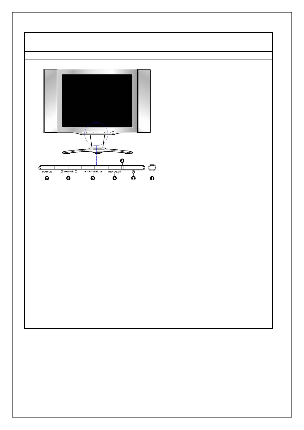
3. Function Control Description
Operation, Adjust and Programming
1. IR Infrared Receiver(IR)
2. POWER Button
Push this button to turn the unit on, and press it one more time to turn it off.
3. LED The LED light indicates when the LCD TV is activated(Green light indicates on and
amber indicates off)
4. MENU/EXIT Button
Press this key to pop up the OSD menu under the current selected input
mode.Press again to turn the OSD off
5.CHANNEL (▲, ▼) Buttons
Press CHANNEL -or + to browse through the TV channels which are not skipped.
Press CHANNEL -or + as up or down select keys to select the OSD menu item.
6.VOLUME (- ,+) Buttons
Press VOLUME -or + to adjust the audio volume increase and decrease.
Press VOLUME -or + as right or left select key to adjust values for the OSD main
menu
7.SOURCE Button
Press the key to select input signal source

HV205
1. POWER
Turns the LCD TV on and into standby mode
2. MUTE
Mutes and restores your LCD TV
3. MTS
Selects the Multi-channel TV Sound (MTS)
options: Stereo, SAP and Mono.
4. SLEEP
Sets up the LCD TV sleep time.
5. SOUND MODE
Selects Sound Mode : Music Hall, News,Stereo,
Surround,Custom,Cinema
6. DISPLAY
Displays information on the LCD TV screen such
as channel and channel label.
7. C.C.
Selects from the following CC functions: OFF,
CC1, CC2, CC3, CC4,
8. 0-9/- --
Select and switch to a channel using 0-9 button,
-/--
To select the channel No., press -/-- to be able to
direct input channels greater than 9.
9. JUMP
Switches back and forth between the current and
previous channels.
10. CHANNEL+/-
Changes the channels up and down
11. VOLUME+/-
Adjusts the volume
12. TV
Directly enter TV mode
13. SOURCE
Selects from different input signal sources:
TV, AV,S-VIDEO,YCbCr/YPbPr, VGA
14. EXIT
Exits the OSD menu(on- screen display)
15. MENU
Displays the OSD menu(on screen display)
16.
Allows to move, select and set the OSD
options
17. CAT MODE(Color Temperature Adjustment)
Selects CAT mode:Standard, Warm, Cool
18. PIC MODE
Selects picture mode:Bright, Soft,Standard,
Custom

ON-SCREEN DISPLAY (OSD)
The On-Screen Display (OSD) shall be an easy to use icon based menu through keypad OSD buttons or
remote control unit. The unit shall leave the factory with all OSD controls set to their default values.
OSD Keypad Buttons
When OSD Menu displayed through pressing MENU button of keypad or remote control unit, the buttons of
VOLUME
and
CHANNEL
in the keypad can be used as the OSD control keys. The functions are:
VOLUME + or - : To select main menu of
IMAGE, PC SETUP, AUDIO, OSD SETUP
and
TV SETUP/CC Mode
DISPLAY
as right or left control keys, or adjust the menu settings when the sub-menu
selected.
CHANNEL cor d: To select sub-menu item as up or down control keys.
OSD Remote Control Buttons
The OSD functions are easy to control and suggested to be through Remote Control Unit. There are 6
buttons including MENU, c, d, f,e, and OK to control it.
MENU button is used to display the OSD, then usef,eas a right or left control key to select the main menu
of
IMAGE, PC SETUP, AUDIO, OSD SETUP
and
TV SETUP/CC Mode DISPLAY
after that c, dto select the sub-
menu item, then use f,eto adjust the sub-menu settings. After the setting, press EXIT to exit.
OSD Menus
The OSD Menus are divided into Main menus and sub-menus, the main menus include the controls of
IMAGE, PC SETUP, AUDIO, OSD SETUP
and
TV SETUP/CC Mode DISPLAY
and when it is selected, the
character will be Grey and show it as the title of sub-menu as the following drawing. The menu of available
adjustment options is dependant on the selected input. User setting/configuration are saved per window.
The OSD Menus would be auto-saved when all the selected functions are quit by users or auto-quit.
SOURCE: TV/AV/S-VIDEO/YCbCr/YPbPr/VGA
IMAGE
Brightness 50
Right/Left to adjust Brightness
Contrast 50
Right/Left to adjust Contrast
Saturation 50
Right/Left to adjust Saturation
Sharpness 50
Right/Left to adjust Sharpness
Hue 50
Right/Left to adjust Hue
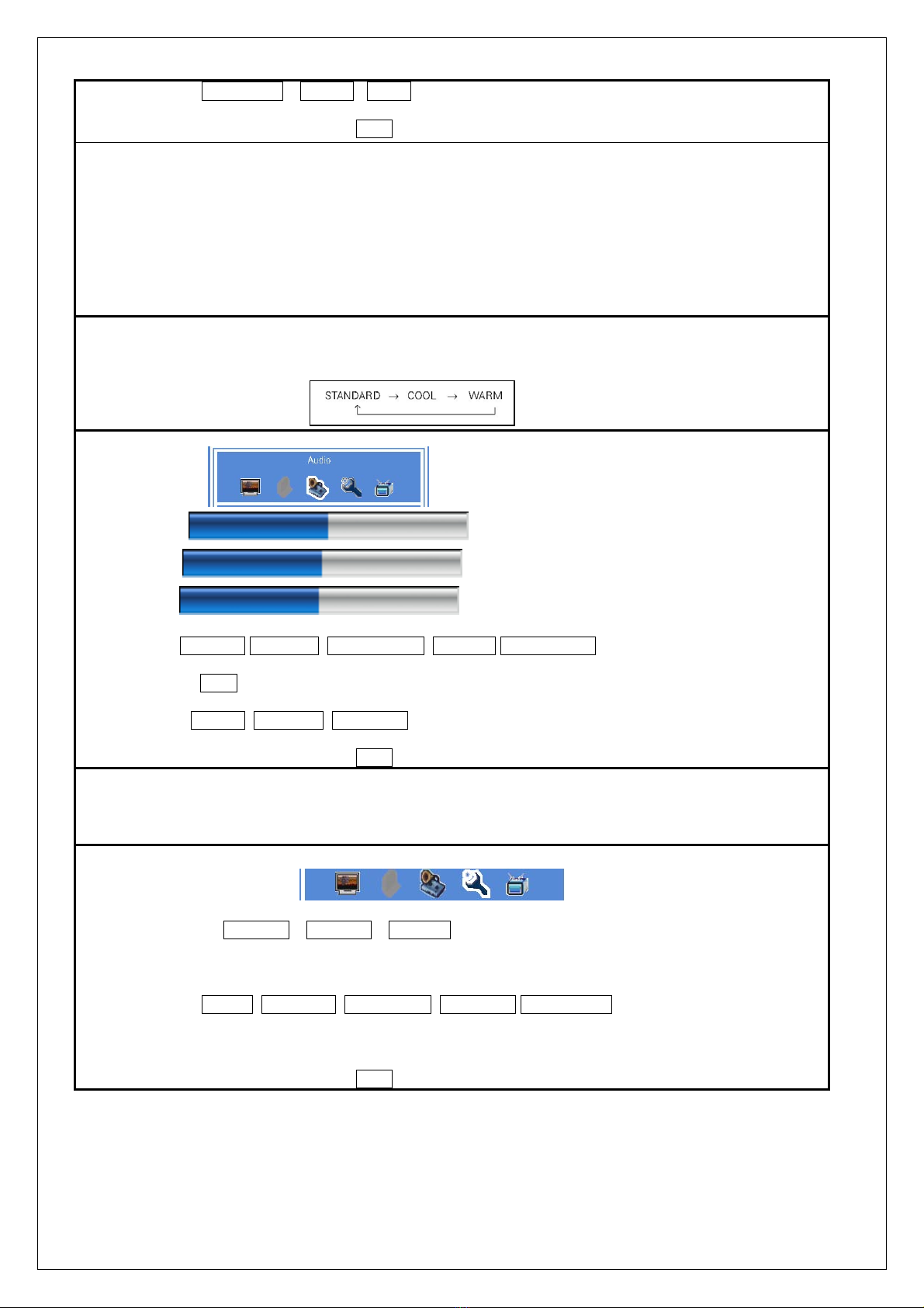
Color Temp Standard Warm Cool
Right/Left to change Color Temp.
Select ef Confirm OK Exit EXIT
a. Display the MENU Press “ MENU “ key of set or Remote control
b. Move through the MENU Press “←“, “→“key of set or Remote control to Select menu
c. Move through the MENU option Press “↑”,”↓” key of set or Remote control to select The control
icon
d. Select an option on change Press “→” key of set or Remote control to change
e. Change an options setting Press”↑”, “↓”,”Å”,”Æ” key of set or Remote To setting
f. Exit the MENU Press “Exit” key on the remote or the MENU/EXIT key on the LCD
TV to exit the operatio
Explanation
1. The Sharpness option can’t adjustable and appear grey on the VGA mode
2. In the Color Temperature option, Press the Left/Right key on the remote control to select Standard,Cool
or Warm
Volume 50
Right/Left to adjust Volume
Bass 50
Right/Left to adjust Bass
Treble 50
Right/Left to adjust Treble
Effect STEREO CUSTOM MUSIC HALL CINEMA SURROUND
Right/Left to change Effect
Woofer
OFF
ON
Right/Left to change Woofer
MTS MONO STEREO SAP
Right/Left to change MTS
Select ef Confirm OK Exit EXIT
Explanation
1. The Bass option and the Treble Option can only be adjusted when Effect option is set to CUSTOM
2.
The MTS mode can only be operated in the TV mode,the MTS can’t be adjusted and appwars grey in the
orther modes
OSD SETUP
Language English France Spanish
Right/Left to change Language
OSD Timer
5~60 secs.
Right/Left to adjust OSD Timer
OSD Position Center Upper-left Upper-right Lower-left Lower-right
Right/left to change OSD Position
RESET
<right> to activate
Select to perform factory reset
Select ef Confirm OK Exit EXIT

TV SETUP
TV System
activate
Adjust TV System
Clock
00:00 0~9 keys to set the clock
Power OFF
00:00 OFF 0~9 keys to set Power OFF
CC Mode Display
OFF Up/Down to select the CC mode display,use
Right/Left to select the CC mode
Vchip Password <right> to activate Adjust the V-chip Password
Select ef Confirm OK Exit EXIT
TV System
1.
Press Up/Down key on the remote control or the
CHANNEL Up/Down key on the LCD TV to selec
the CABLE option,use Left/Right key on the
remote control or the VOLUME +/- key on the LCD
TV to select the CABLE to be IRC,HRC or
STD,press OK key to confirm it.
2.
Press Up/Down key on the remote control or the
CHANNEL Up/Down key on the LCD TV to select
the Channel Scan,Use OK key on the remote
control or the Volume +/- key on the LCD TV to
start Scan
3.
Press EXIT key on the remote control or the
MENU/EXIT on the LCD TV to exit the operation
1. Press Up/Down key on the remote control or the
CHANNEL Up/Down key on the LCD TV to select
the option(Channel No, Status).
2. Press Left/Right key on the remote control or the
Volume +/- key on the LCD TV to adjust the
selection option.
3. Press EXIT key on the remote control or the
MENU/EXIT on the LCD TV to exit the operation

V-Chip Password
4. Circuit Description
(1) Voltage Regulator circuit
External AC power supply AC 90 V to 264V , and the input frequency within 50/60Hz can be applyied.
Intramural adapter converts AC voltages to DC voltage, The usage of each output:
12V, 8V, 5V,3.3V, 1.8V
(2) Controller
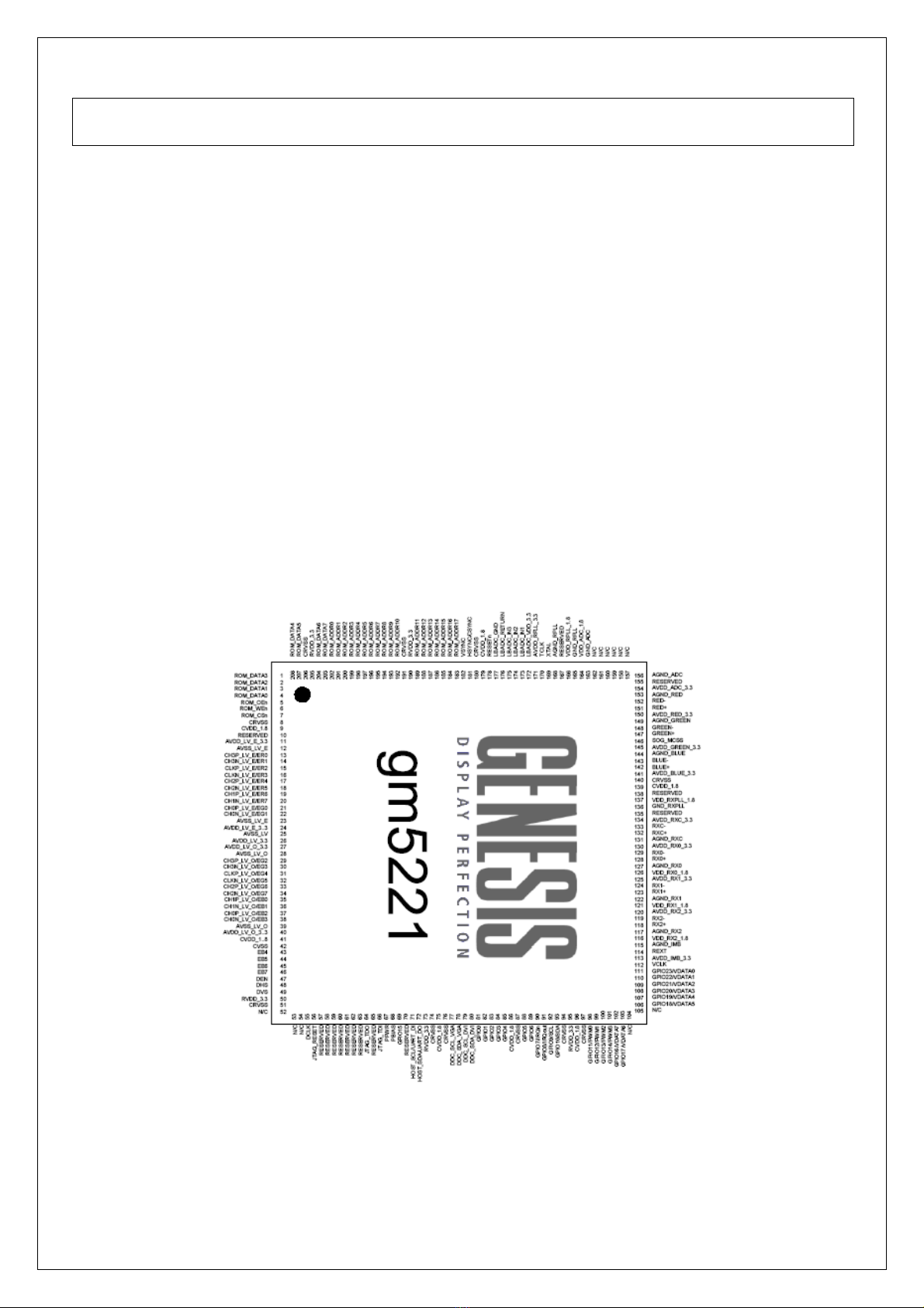
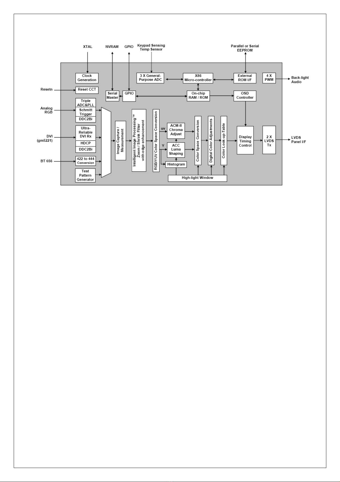
gm2221/gm5221 Integrated Multimedia LCD Controller
The gm5221 device is an all-in-one LCD monitor controller supporting resolutions up to SXGA (1280x1024). The gm5221
leverages Genesis patented advanced image-processing technology as well as a proven integrated ADC/PLL, an Ultra-
Reliable DVI™ compliant digital receiver, and a CCIR656 video input port to deliver a high-quality, low cost solution for
multifunction LCD monitors. On-chip, industry standard, single/double-pixel, four-channel LVDS 6/8-bit transmitters
connect directly to commercial available LCD panel modules. In addition, an integrated X86 microcontroller and OSD
engine are provided. This high level of integration reduces the number of components. This reduces system cost, improves
reliability and simplifies monitor design.
----Intelligent Image Processing™
----Analog RGB Input Port
----CCIR-656 8-bit Video Input Port
----Advanced Color Management
----On-chip Versatile OSD Controller
----Embedded X86 On-chip Microcontroller
----Built-in Test Pattern Generator
----Energy Spectrum Management (ESM™)
----Built-in LVDS Transmitters
----Highly integrated System-on-a-Chip
(3) Video
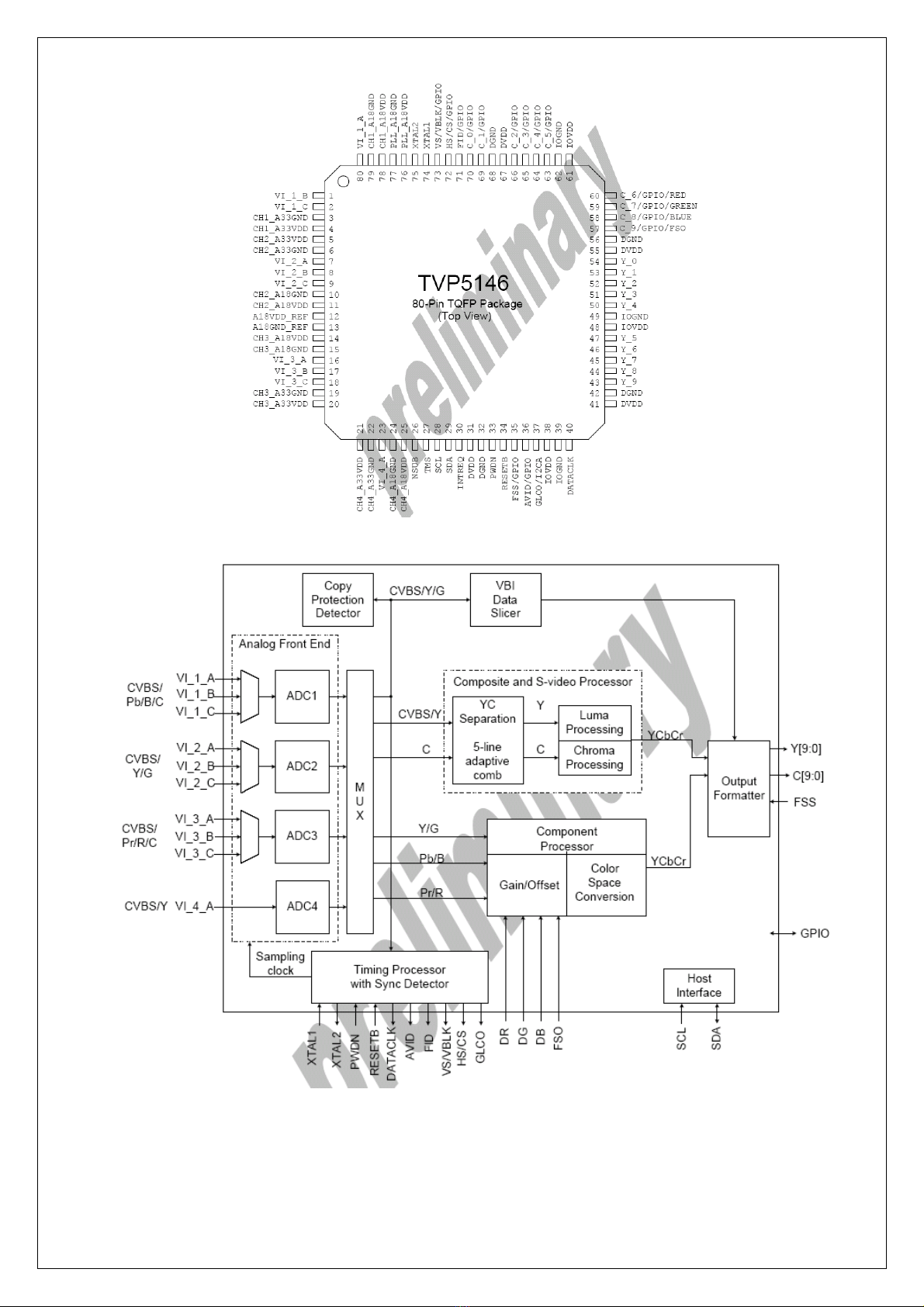
Video Decoder TVP5146
The TVP5146 is a high-quality,single-chip digital video decoder that digitizes and decodes all popular base-
band analog video formats into digital component video.TVP5146 supports the A/D conversion of component
RGB and YPbPr signals,as well as the A/D conversion and decoding of NTSC,PAL and SECAM composite
and S-Video into component YCbCr.The main features of the TVP5146 are:
----four 30-MSPS,10-bit A/D Channels with programmable clamp and gain control
----supports NTSC(J,M,4.43),PAL(B,D,G,H,I,M,N,Nc,60) and SECAM(B,D,G,K,K1,L)CVBS,S-video
----supports analog component YPbPr/RGB video formats with embedded sync
----10 analog video input terminals for multi-source connection
----user-programmable video output formats
----HSYNC/VSYNC outputs with programmable position,polarity and width and FID output
----component video processing
----composite and S-video processing
----vertical blank interval data processor
----I2C host port interface
----
reduced power consumption:1.8V digital core,3.3V and 1.8V analog core with power-save and power-down modes
----embedded RAM to allow user-downloadable configuration micro code(feature upgrade)
----80-pin TQFP PowerPADTM package
(4) Audio
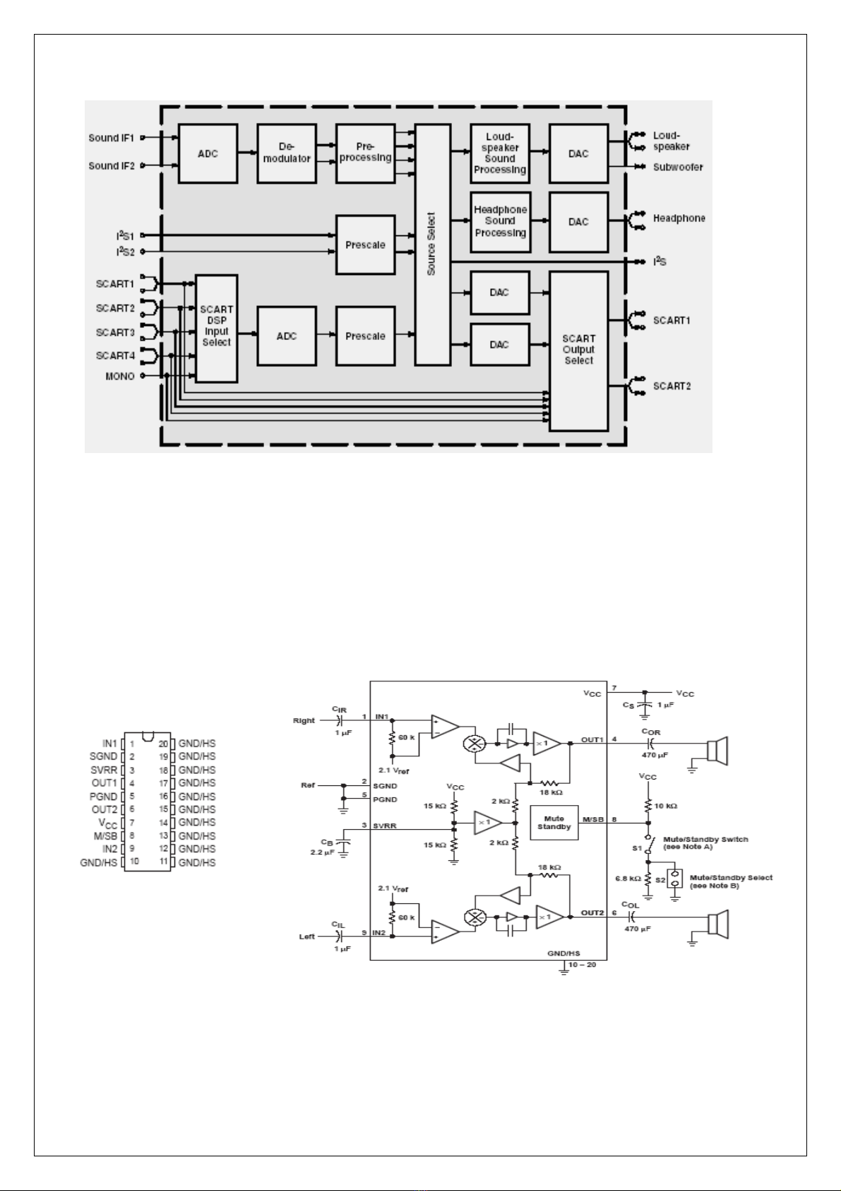
Audio Decoder MPS34X0G
The MSP 34x0G family of single-chip Multistandard Sound Processors covers the sound processing of all
analog TV-Standards worldwide, as well as the NICAM digital sound standards. The full TV sound processing,
starting with analog sound IF signal-in, down to processed analog AF-out, is performed on a single chip.
Below Figure shows a simplified functional block diagram of the MSP 34x0G.
This new generation of TV sound processing ICs now includes versions for processing the multichannel
television sound (MTS) signal conforming to the standard recommended by the Broadcast Television Systems
Committee (BTSC). The DBX noise reduction, or alternatively, Micronas Noise Reduction (MNR) is performed
alignment free. Other processed standards are the Japanese FM-FM multiplex standard (EIA-J) and the FM
Stereo Radio standard.
Current ICs have to perform adjustment procedures in order to achieve good stereo separation for BTSC and
EIA-J. The MSP 34x0G has optimum stereo performance without any adjustments. All MSP 34xxG versions
are pin compatible to the MSP 34xxD. Only minor modifications are necessary to adapt a MSP 34xxD
controlling software to the MSP 34xxG. The MSP 34x0G further simplifies controlling software. Standard
selection requires a single I
2
C transmission only. The MSP 34x0G has built-in automatic functions: The IC is
able to detect the actual sound standard automatically (Automatic Standard Detection). Furthermore, pilot
levels and identification signals can be evaluated internally with subsequent switching between
mono/stereo/bilingual; no I
2
C interaction is necessary (Automatic Sound Selection). The MSP 34x0G can
handle very high FM deviations even in conjunction with NICAM processing. This is especially important for
the introduction of NICAM in China.
The ICs are produced in submicron CMOS technology. The MSP 34x0G is available in the following packages:
PLCC68 (not intended for new design), PSDIP64, PSDIP52, PQFP80, and PLQFP64.
Audio Amplifier. TPA1517
The TPA1517 is a stereo audio power amplifier that contains two identical amplifier capable of delivering 6W
per channel of continuous average power into a 4 Ohm load tat 10THDN or 5W per channel 1THD
N. The gain of each channel is fixed at 20dB. The amplifier features a mute/standby function for power-
sensitive applications.

5. Adjusting Procedure
ITEM
P
rogram
Menu.
Equipments Requirements Procedure and SPEC
1 Erase EEPROM
A. Press MENU &CHANNEL- button on the
equipment, and to select “Color Temp” option
B. Press SOURCE button three times on the
equipments, and the equipment auto erase
EEPROM.
C.The led is orange and flash when the
equipment erasing EEPROM, the led is red
and flash when erase EEPROM is over,
D. Swtich off power, then switch on power.
2
Into Factory
MENU
A. Press MENU &CHANNEL- button on the
equipment, and to select “Brightness” option.
B. Press SOURCE button three times on the
equipments, and into “Factory Setting” menu.
3Burn in Set
A. In “Factory Setting” menu, to select
“Advanced Setting” option, set “FACTORY
MODE” is 1.
B. Exit “Factory Setting” menu, to select
“VGA” mode, into burn in status when no
signal.
C. OSD is burn in time when burning in, OSD
is “Burn in OK” when burn in is over.
D. when burn in is over, swtich off power, then
switch on power
4ADC Adjust PC or Pattern
Generat
1024X768/60Hz
5-MOSAIC pattern
In “VGA” mode, into “Factory Setting” menu,
to select “Color Setting\Auto Adjust” option,
press “VOLUME-” or “VOLUME+”, the
equipment auto adjust ADC.
5. Default Set
When set user menu is over, into “Factory
Setting” menu, then exit “Factory Setting”
menu.
Notes: exit “Factory Setting” menu before,
confirm “Advanced Setting\FACTORY
MODE” set is 0,
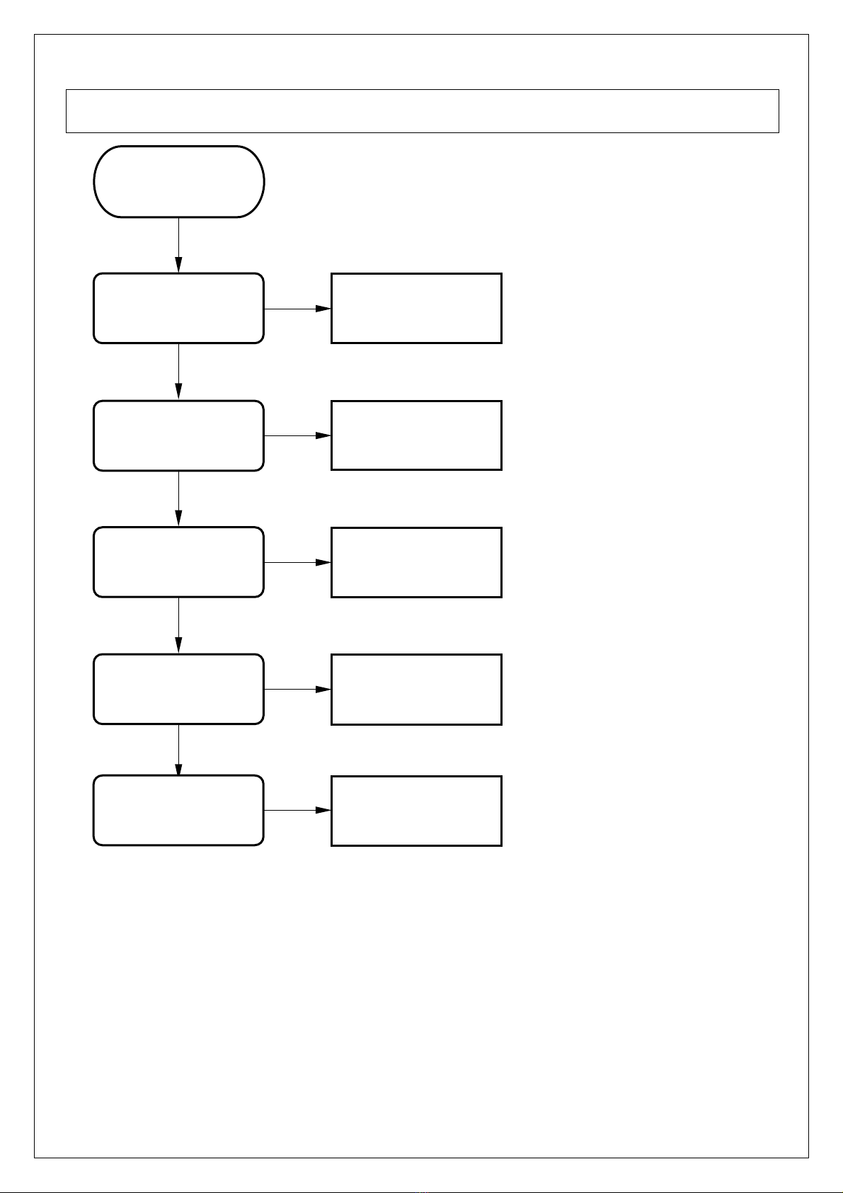
6. Trouble Shooting Flow Chart
NO
YES
NO
YES
NO
YES
NO
YES
NO
No Display
( TV )
Check U3 Circuit
Check U17 Circuit
Check TV
Input Signal ?
Check
B+ Circuit ?
TV
Signal Cable ?
Tuner B+ ?
U17 Video
Processor ?
U3 Controller ?
PANEL ?
Check PANEL
Table of contents


