PSB SubSeries 500 User manual

Powered Subwoofer
Caisson de sous-grave amplifié
Altavoz Subgrave con Amplificador
PSB SubSeries
500
Owner’s Manual
Guide d’utilisation
Manual de Propietario


CONTENTS
I.
II.
III.
IV.
V.
VI.
VII.
A.
B.
C.
D.
E.
F.
G.
H.
I.
J.
K.
L.
VIII.
A.
B.
C.
D.
IX.
X.
XI.
Important Safety Instructions
Introduction
Warranty Registration
Cabinet Care
Room Acoustics, Subwoofer Placement, Multiple Subwoofers
and Setting the Controls
Quick Start
Features, Controls, AC Power
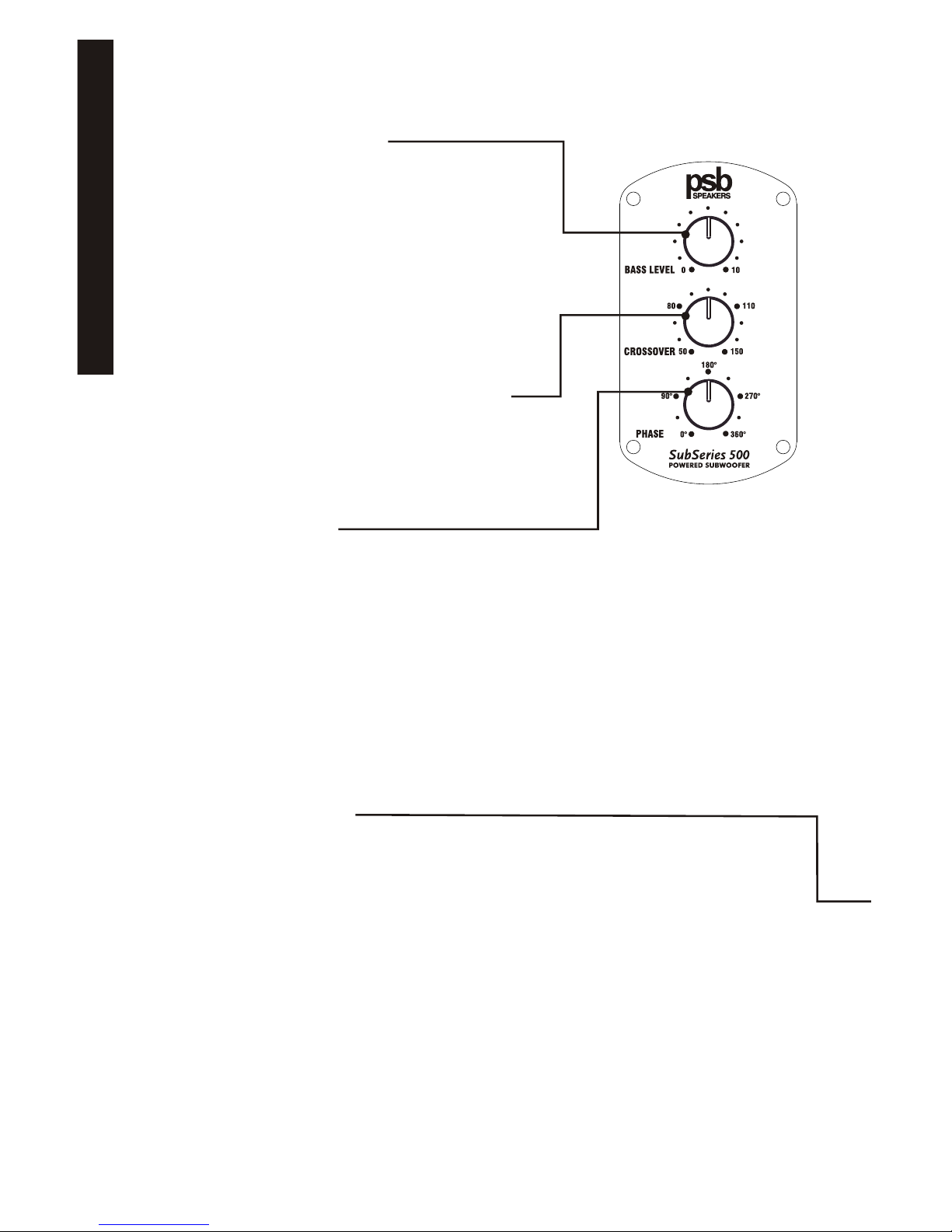
Sub Volume Control (Figure 1)
On Indicator Light (Figure 1)
AC Power Connection
Sub Cut-Off Frequency Control (Figure 1)
Phase Control (Figure 2)
LFE Jacks (Figure 2)
Low/Line Level Jacks (Figure 2)
High/Speaker Level Terminals (Figure 2)
Power Switch (Figure 2)
Amplifier Panel (Figure 2)
AC Power Socket (Figure 2)
External Fuse (Figure 2)
Connecting The Subwoofer To Your Audio System
Connecting Home Theater Equipment
Connecting Stereo Equipment Using Low/Line Level
Connecting Stereo Equipment With High/Speaker Level
Using Multiple Subwoofers
Set-up Calibration
In Case Of Problems
Specifications
3
Owner’s Manual

IMPORTANT SAFETY INSTRUCTIONS
1. Read these instructions.
2. Keep these instructions.
3. Heed all warnings.
4. Follow all instructions.
5. Do not use this apparatus near water.
6. Clean only with dry cloth.
7. Do not block any ventilation openings. Install in accordance with the manufacturer's instructions.
8. Do not install near any heat sources such as radiators, heat registers, stoves, or other apparatus
(including amplifiers) that produce heat.
9. Do not defeat the safety purpose of the polarized or grounding-type plug. A polarized plug has
two blades with one wider than the other. Agrounding type plug has two blades and a third
grounding prong. The wide blade or the third prong is provided for your safety. If the provided
plug does not fit into your outlet, consult an electrician for replacement of the obsolete outlet.
10. Protect the power cord from being walked on or pinched particularly at plugs, convenience
receptacles, and the point where they exit from the apparatus.
11. Only use attachments/accessories specified by the manufacturer.
12. Unplug this apparatus during lightning storms or when unused for long periods of time.
13. Refer all servicing to qualified service personnel. Servicing is required when the apparatus has
been damaged in any way, such as power-supply cord or plug is damaged, liquid has been spilled
or objects have fallen into the apparatus, the apparatus has been exposed to rain or moisture,
does not operate normally, or has been dropped.
14. WARNING: To reduce the risk of fire or electric shock, this apparatus should not be exposed to
rain or moisture
and objects filled with liquids, such as vases, should not be placed on this apparatus.
15. To completely disconnect this equipment from the mains, disconnect the power supply cord plug
from the receptacle.
16. The mains plug of the power supply cord shall remain readily operable.
The lightning flash with arrowhead symbol within an equilateral triangle is
intended to alert the user to the presence of uninsulated "dangerous voltage”
within the product's enclosure that may be of sufficient magnitude to
constitute a risk of electric shock to persons.
The exclamation point within an equilateral triangle is intended to alert the
user to the presence of important operating and maintenance (servicing)
instructions in the literature accompanying the product.
Notes on environmental protection
At the end of its useful life, this product must not be disposed of with regular household
waste but must be returned to a collection point for the recycling of electrical and electronic
equipment.Thesymbolontheproduct,user'smanualandpackaging,pointthisout.
The materials can be reused in accordance with their markings. Through re-use, recycling
of raw materials, or other forms of recycling of old products, you are making an important
contributiontotheprotectionofourenvironment.
Yourlocaladministrativeofficecanadviseyouoftheresponsiblewastedisposalpoint.
4
Owner’s Manual

II. Introduction
PSB subwoofers are designed to provide the flattest possible frequency
response, full bass extension, low distortion and high output. Frankly,
these are characteristics that most manufacturers would strive for. Our
years of experience and our sophisticated design and measurement
tools allow us to achieve ideal subwoofer performance. Beyond these
characteristics there are a few other parameters that we uniquely feel are
very important in the design of a subwoofer. First and foremost it is
important to us that a PSB subwoofer be musical. In this era of home
theater this might at first seem out of step, but we believe that a musical
subwoofer will also sound the most natural when playing movie
soundtracks. Furthermore, an ideal subwoofer should have the ability to
play musically even under conditions of overload or stress. No
subwoofer is so large with its limits so great that it can never be
overloaded, especially with modern movie soundtracks. For this reason
PSB subwoofers incorporate very intelligently applied proprietary limiting
circuitry to prevent audible overload.
The limiting circuitry of all PSB subwoofers is a combination of peak
limiting circuits that hold amplifier signal swing to the point just short of
the amplifiers clipping, and compression circuitry that will come in under
conditions of long term overload and reduce the amplifiers gain. The
trick is to apply these circuits in such a way that they don't squeeze the
life out of the music or movie soundtrack, to allow the dynamics to get
through while preventing gross distortion. We do this by being mindful of
the dynamics of music and carefully tailoring the time constants of the
circuits to that of music. For example, it is known that most music is
performed with a beat of 80 to 140 beats per minute. Our test signals are
configured to follow this timing and allow maximum transient effect
without distorting on sustained tones.
We go to great lengths to reduce any mechanical noises our subwoofers
may make. Woofers are designed never to bottom harshly. Ports have
large radius end flares to reduce noise from turbulence. Cabinets and
amplifiers are designed so that no air leaks (which can contribute minute
amounts of noise) are possible. All of our designs are exhaustively
tested. A subwoofers design isn't complete until the sub's amp and
woofer can survive a 15 hour test of being driven continuously to
maximum output.
SubSeries 500
As in all other current SubSeries subwoofers, this subwoofer utilizes a
high efficiency high power class H power amp. Class H is a special high
efficiency amplifier design. Briefly, audio amplifiers are inherently
inefficient because they are designed to have the capability of delivering
great output power yet spend most of their life delivering fairly low power.
Their output devices must deliver current while withstanding the high
5
Owner’s Manual

power supply “rail” voltages needed for peak outputs. With a Class H
design the rail voltages are not constant. They swing high when the
music demands it and stay low during quiet passages. This is achieved
by a sophisticated high frequency switching power supply. Power
dissipated as heat is greatly reduced and more power is available per
dollar of cost. A second benefit is that they tend to have high peak
power relative to their steady state power. The SubSeries 500, for
example, has 500 watts continuous power and is capable of over 1500
watt peaks. The result is a subwoofer capable of the great transients
required by dynamic music and explosive sound effects. The SubSeries
500 offers the latest most efficient implementation of this special Class H
technology.
The SubSeries 500 cabinet is constructed from thick MDF and aluminum
extrusions. These materials and their application in this design form an
extremely rigid cabinet free of any audible resonances due to panel or
brace movement. Large curvilinear ports with large radius flanges
drastically reduce port noise to inaudible levels while minimizing acoustic
compression common to smaller diameter port designs. Air will create
noise whenever it comes into contact with a hard surface. Minimizing the
area of the surface that the air actually comes in contact with reduces
this noise.
A severe duty aluminum cast basket, very large magnet structure, and a
high power voice coil allow the SubSeries 500 to effortlessly churn out
low frequencies at foundation shaking levels.
III. Warranty Registration
We recommend you take a few moments now to register your warranty
on-line at www.psbspeakers.com so that we will be able to serve you
better in the future.
Unpacking
The packing materials are designed to protect your subwoofer from
damage during shipping. Retain the packaging in case the need arises to
transport the speaker in the future.
IV. Cabinet Care
Cabinets have varying materials and finishes, including wood veneers
and painted cast anodized aluminum parts. They should be treated as
you would any fine furniture with similar finishes. Dust lightly with a soft
cloth; avoiding abrasives. If necessary, wipe carefully with a cloth slightly
dampened with glass cleaner to remove heavy soil.
Grille
A lint brush does a good job of cleaning grilles. Grilles can be taken off
and vacuumed if you prefer. Avoid touching speaker diaphragms.
6
Owner’s Manual

V. Room Acoustics, Speaker Placement, Multiple
Subwoofers and Setting Controls
Room Acoustics
If you are critical about low-frequency response, there's quite a bit of
useful experimentation you can do, especially in combination with the
crossover, level, and phase controls of our subwoofers.
Since the earliest days of high fidelity, one of the main challenges for the
designers of speakers, and of their users, has been management of the
lowest frequencies—the deep bass. Many of the most notable
developments in speaker design have been made with a view to getting
more bass output from smaller boxes.
One consideration is the size of the listening room. The larger the
volume of air a speaker must excite, the more acoustic output you will
require from it to achieve the sound levels you want. In any environment,
sounds attenuate as you move farther away from their source, but in
smaller rooms that tends to be offset by reinforcement from wall
reflections. The larger the space is, the farther the sound has to travel
both to reach the reflecting surfaces and then to get to your ears, which
means it has to be louder to begin with.
With traditional full-range speakers, that involves an intricate matching
act between amplifier power, speaker sensitivity, impedance and power
handling. But the bulk of the power goes to reproducing bass, so the use
of powered subwoofers and separate midrange/treble satellites both
allows you to be conservative in the amount of power your main amplifier
produces, and ensures a good match between the low-frequency
amplifier and the woofer it is paired with.
After size, the most important aspect of a listening room is its shape. In
any room, sound reflects off the walls, ceiling, and floor. If the distance
between two opposite parallel surfaces is a simple fraction of the
wavelength of a particular frequency, notes of that frequency will bounce
back and forth in perfect phase—an effect called a standing wave or
room mode.
At some point in the room, this note will be reinforced substantially; at
others it will cancel out almost entirely. If the prime listening seat is
placed at either of these locations, the note will be a horrible boom or
virtually non-existent. The standing waves are different between floor
and ceiling, side walls, and end walls, unless any of these dimensions
are the same. An ideal listening room would have no parallel
surfaces—an unusual situation, to say the least—so that such waves
would not establish themselves. The worst kind of room is a perfect cube.
Almost all rooms are susceptible to some standing waves at low
frequencies, but their effects can be minimized by careful positioning of
both the speakers and the listening seat. Moving either of these even a
7
Owner’s Manual

few inches is sometimes enough to cure—or create—an intolerable
sound. The only way to find out what works best is by experimentation.
With full-range speakers, the range of places you can put the speakers
and still get proper imaging may be fairly limited, and some of these
positions may result in standing waves that can't be tamed. Things are
more controllable through the use of a subwoofer or two. Positioning of
the bass speakers has almost no impact on imaging, so a subwoofer
can be located with only standing waves in mind
Subwoofer Placement
There is no argument among audiophiles that the loudest bass output
from a subwoofer comes from corner placement. The natural
megaphone-like flaring outward of walls from a room corner focuses low
frequencies—giving them no place to go but toward you. In the case of
subwoofers, there is no automatic penalty in giving overall balance for
this maximal bass, since your main speakers can be located elsewhere.
It still may be too much bass for your room or (more particularly) your
favorite listening spot in the room, but unless you are seated in a “null”
spot, where sound from the sub is cancelled or diminished by out-of-
phase reflections from elsewhere, there should be plenty of bass from
corner placement.
If you are seated in such a null spot, your only real choices are
generally to move either the subwoofer or your listening position until
bass returns to the point that satisfies. Cranking up the level control or
changing the crossover point almost certainly won't help much. But
flipping the phase control 180 degrees sometimes may make a
difference, especially if the null is a product of cancellations caused by
interaction with low frequencies from your main speakers.
If you are in the opposite sort of situation, where direct and reflected
bass waves converge in phase and produce a strong peak at your
listening location, you can—if you like—deal with that both with changes
in placement or in the position of your sub's level control (or, less likely
but possible, the crossover frequency chosen). We say “if you like”
because there is no such thing as too much bass for some listeners,
and we don't want to be dogmatic. You are definitely the one who has to
be pleased, unless your Significant Other chimes in to the contrary.
8
Owner’s Manual

As you go outward from the corner along one wall or another, the general
consensus (with which we tend to agree)
is that while bass output diminishes somewhat, it also becomes more
uniform throughout the room, with fewer of the “standing waves” that
produce peaks and nulls at various points.
Chances are things won't be so simple, so the best method for
positioning a subwoofer, although a rather undignified-looking one, is to
put the subwoofer in your listening chair, then play music with lots of
bass through the system something with steady low frequencies (such as
organ music) or continuous test tones, not movie material. Move around
the room and note where the bass sounds best; if you place the
subwoofer there and yourself in your chair, you should get the same
bass performance. Bear in mind that the test only works if you have your
ears as high off the floor as the subwoofer will be, so don't be afraid to
crawl around. A recommended starting point for the placement of this
subwoofer would be in either of the front corners of the room (on either
side of the main speakers).
Multiple Subwoofers—Why Two Subs Are Better Than One
Since the objective of most people who buy subs is to make sure of
plentiful low frequencies, the only situation most of us will run into that
makes subwoofer placement really difficult is the factor we all fear—the
“bad” room that just won't let you get satisfying amounts or quality of
bass. There are rooms with troublesome dimensions, especially as you
approach a perfect cube (with a closed door). There is unlikely to be any
combination of speaker and listener position that will be free of obvious
acoustic anomalies.
In such a case, the best way to iron out those anomalies is with two
subwoofers, placed carefully to work with each other. This can also be
true when the problem is too much, or too uneven, bass. The overall
system needs all the help it can get, and that often means the use of two
subwoofers, each one of which corrects for the acoustic problems
excited by the other. For excellent results from this solution, the two subs
don't have to be identical. It may be fine, in fact, to use two lesser subs to
equal the performance of one with stronger specs.
The same “crawl around the room” method as previously described
should be used for determining the location of the second subwoofer,
except in this instance one is listening for the minimum amount of bass
output. This is a recommended starting point for determining the best
placement for your subwoofer(s).
Setting the Subwoofer Controls
Once a reasonably smooth response has been achieved by careful
positioning of the subwoofers, the overall performance can be fine-tuned
by means of the controls found on the speaker. An important one is the
9
Owner’s Manual

low-pass filter, which controls the upper limit of the subwoofer's
frequency range. This should be set high enough to overlap the low
frequency cutoff of the satellite speakers, but not high enough to localize
specific sounds from the sub.
If the frequency response of your satellite speakers is such that the
subwoofer's low-pass filter must be set higher than about 80Hz in order
to avoid gaps in the overall system response, then you might well be able
to localize specific sounds from the sub. This can be very distracting
when these sounds appear to come from beside or behind you. One
solution is to make sure the subwoofer is in the front of the listening area;
another is to use multiple subwoofers to make such sounds more diffuse.
Subwoofers also offer a phase control so the upper frequencies they
produce will not cancel out the lower frequencies of the satellites. A
judicious tweaking of this control can pay major dividends in spectral
smoothness in the crossover area. Phase changes with frequency,
however, so these controls may need readjusting every time you vary the
cutoff frequency.
Also adjustable is the overall level of the subwoofer's output. Many users
tend to set this too high at first, in an effort to achieve truly impressive
bass. Again, smooth response is the aim, and it may well be that, if you
use them, two subwoofers end up being set differently—if, for example,
one is in a corner and the other is not. It's all part of the overall-balancing
act that is bass management in real rooms.
We get virtually no inquiries about subwoofer placement from customers,
which is a good indication that it's not something over which people lose
much sleep. A good subwoofer is such a pleasure when used with a
good main speaker that enjoyment is definitely the rule.
VI. Quick Start
If you cannot wait to hear your new PSB subwoofer: Turn off all other
components, and follow one of the connection diagrams. Connect the
supplied power cord to the AC power socket. Set the PSB subwoofer
volume control to its minimum position (counterclockwise), then plug the
subwoofer into an active AC outlet. The same receptacle as the rest of
your audio/video system or another on the same electrical circuit should
be used to avoid ground hum. Set the subwoofer's Sub Cut-Off
Frequency control to its midpoint, and the phase switch to 0°. Flip the
Power Switch to the on position. Play a bass-rich program source, and
slowly bring up the Sub Volume control (clockwise) until the subwoofer
contributes a natural level of low frequency sound. Now please read the
rest of this guide and fine-tune your installation accordingly—it will be
time well spent!
10
Owner’s Manual

Adjustable Rubber Leveler and Adjustable Spike Installation
Screw the supplied levelers or spikes into the threaded inserts located in
the base, bottom or in the four feet attached to the bottom of the
subwoofer. Speaker spikes are for carpet use. Threaded rubber isolation
levelers are for shelf or hard floor use.
a) Carpet Use
Screw a spike with a lock nut attached into the insert located in the
base, bottom or in each of the four feet attached to the bottom of the
subwoofer. Locate the subwoofer, adjust to the desired height
(higher for thicker carpet) by turning the spikes and tightening the
lock nuts.
b) Hard Floor or Shelf Use
Screw a threaded rubber isolation bumper with a lock nut attached
into the insert located in the base, bottom or in each of the four feet
attached to the bottom of the subwoofer. Locate the subwoofer,
adjust to the desired height by turning the rubber isolation bumpers
and tightening the lock nuts.
11
Owner’s Manual
(Located on the front on the Subwoofer directly below the
woofer) With both the 120 and 230 volt versions, the
subwoofer is initially in stand-by mode awaiting the presence of
an audio signal. The indicator is red in the standby mode. When
the subwoofer receives an audio signal the On indicator colour
will change to green. At the end of the audio signal the
subwoofer will stay on for approximately 15 minutes.
VII. Features, Controls, AC Power
D. ON INDICATOR LIGHT
A. SUB VOLUME CONTROL
(located on the front
of the subwoofer)
Figure 1
Adjusts the output level of the PSB subwoofer only: This is
not intended as a day-to-day volume control. See “IX.
Setup Calibration”
The PSB subwoofer includes designed-in dynamic-range
protection: it is virtually impossible to overdrive the
subwoofer, regardless of volume setting or the demands
of the program material.
Where even higher levels of low frequencies are required,
a second PSB subwoofer can provide a significant gain in
total bass levels.
C. PHASE CONTROL
Adjusts the subwoofer output phase between 0° and 360° to
compensate for the low to mid bass acoustic effects of different
placement locations and listening rooms.
See “IX. Setup Calibration”.
B. SUB CUT-OFF FREQUENCY CONTROL
Adjusts the high-frequency roll-off of signals sent to the
subwoofer. Continuously variable from 50Hz to 150Hz for
precise matching of subwoofer bass reproduction with the
main (left and right) stereo speakers. See “IX. Setup
Calibration”
E. AC POWER SOCKET
Supplies AC power to the PSB subwoofer. Connect the supplied
power cord to the AC power socket. Plug the power cord into
any standard wall outlet. With 230 volt versions, in some
countries it may be necessary to replace the power cord to
meet the standards in use locally. The same receptacle as the
rest of the system or another on the same electrical circuit
should be used to avoid ground hum.
The PSB subwoofer has its own self-contained amplifier and
thus requires AC power (keep this in mind when selecting a
location). You may plug the power cord into any standard wall
outlet and leave the connection in the wall as the PSB
subwoofer draws extremely little current when idle. You may
want to unplug your PSB subwoofer when it will not be used for
an extended period such as a vacation.
12
Owner’s Manual

LFE OUTPUT
LFE INPUT
500
SubSeries
TRIGGER INPUT
9-30V AC/DC
S/N
Figure 2
F. LFE JACKS
G. LOW/LINE LEVEL JACKS
I. POWER SWITCH
J. AMPLIFIER PANEL
The metal provides cooling for
the PSB subwoofer’s internal
amplifier by radiating heat
produced in normal operation.
Allow air circulation, including at
least four inches clearance from
wall or furnishings.
Connect the PSB subwoofer to a
separate-component preamplifier,
or to an integrated amplifier or
receiver with preamplifier-
out/main-in facilities, at line level.
See “VIII. Connecting The
Subwoofer to Your Audio
System”.
The Power Switch turns the PSB
subwoofer on and off. As the
subwoofer draws only an
extremely small current when idle,
this may be left normally on and
turned off only when you do not
expect to use the subwoofer for
an extended period. The Power
Switch must be in the on position
for normal operation.
H. HIGH/SPEAKER LEVEL
TERMINALS
Connect the PSB subwoofer to
receivers or integrated amplifiers
equipped with speaker outputs
only. See “VIII. Connecting The
Subwoofer to Your Audio
System".
When you turn on the subwoofer and there is no
LED light and/or sound, please check the fuse
(accessible from the rear panel) to ensure it is
electrically intact. The fuse could have become
broken during transit. A spare fuse is contained
within the fuse holder compartment behind the
inscribed text. Use a wide slot screwdriver to pry
the fuse holder compartment from the AC power
socket. If it is necessary to replace the fuse, use a
fuse equivalent to the type and rating of the fuse
shipped with the product. See the specifications
page at the end of the manual for a detail
description of the fuse required for your model of
subwoofer.
K. EXTERNAL FUSE
Connect to a home theater
receiver, integrated amplifier,
surround sound processor or
preamplifier with a Low
Frequency Effects (LFE) output.
13
Owner’s Manual
The Subwoofer can be turned on (brought out of standby) by an
external trigger (turn on) voltage. Connect an external trigger
voltage via a cable terminated with a mono mini jack of 3mm
(1/8”) size. Voltages within the range of 2 to 30 volts, either AC
or DC, will work. Do not exceed 30 volts (DC or RMS AC). For
DC voltages the tip should be positive and the base ground.
Either the trigger voltage or detected music will turn the
subwoofer on. It will return to standby mode one hour after both
music and the turn on voltage cease.
L. TRIGGER INPUT JACK

VIII. Connecting The Subwoofer To Your Audio System
There are several ways to connect a subwoofer into a system. For best
results overall, we recommend using Low/Line Level connections.
When making a Low/Line Level connection, be sure to follow the coding
on the cables to maintain left-to-left and right-to-right. Use high quality,
well-shielded, low capacitance RCA cables of minimal necessary length,
to avoid picking up noise in the cable runs. When making a High/Speaker
Level connection, in addition to maintaining left-to-left and right-to-right,
be sure to use the coding of the pair of wires in each speaker cable to
maintain phase—+/red/rib/writing to +/red/rib/writing and -
/white/smooth/clear to -/white/smooth/clear. We recommend minimum 16
gauge wire and, for longer runs, larger (lower gauge) wire.
A. Connecting Home Theater Equipment
(see Figure 3, page 19):
You can use a single RCAcable to connect the Subwoofer Output
of your receiver, integrated amplifier, or preamplifier to either right or
left side of the Low Level Input on the subwoofer.
Home Theater receivers, integrated amplifiers, surround sound
processors, and preamplifiers usually have a special Subwoofer
Output to provide the optional (Dolby Digital 5.1) Low Frequency
Effects (LFE) Channel present on many movie and other
programming sources. To reproduce these deep-bass effects (when
they are present), supplementing the bass information in the main
channels, this output must be connected to the subwoofer.
The subwoofer output/LFE signal is filtered by most
receivers/processors. The subwoofer's variable low pass filter is
usually not required and should be bypassed by using the LFE Input
only if the receiver/processor subwoofer/LFE output is low pass
filtered.
With some Home Theater electronics and settings, connecting the
Subwoofer Output does not provide the low frequencies from
normal stereo music through the subwoofer. If this is true of your
system, you can make two connections. First, connect the
Subwoofer Output from the electronics to the right or left side of the
Low Level or LFE Input of the subwoofer, as described above. Then
also connect the High Level Output from the electronics to the High
Level Input of our subwoofer, as described below. Most Home
Theater electronics will not require this second connection, which, if
not required will produce greater bass than intended.
B. Connecting Stereo Equipment Using Low/line Level
(see Figure 4, page 20):
If your receiver or integrated amplifier has preamplifier outputs, or if
14
Owner’s Manual

substantial deep-bass content over an extended section. Your PSB
dealer can help you select a few such titles.
C. Gradually turn the Sub Volume control clockwise until you achieve
natural balance between the subwoofers deep-bass output and your
main left and right loudspeakers.
D. Slowly turn the Sub Cut-Off Frequency control clockwise to reach
the best mid-bass blend with your main left and right speakers. This
will be the point at which the upper bass retains solid impact and
fullness. Boom or muddiness is the result if the control is too high. A
thin, “reedy” quality to the mid-bass such as deep male voices (FM
announcers; Darth Vader) is the result if the control is too low.
E. Adjust the Phase control between 0° and 360° several times,
leaving it in the position that yields the fullest low to mid bass output.
You will now probably want to repeat steps C & D to double-check
the subwoofer blend.
Cycling through steps C & D several times with slightly different settings
of both the Sub Volume and Sub Cut-Off Frequency controls will help you
get the most musical performance from your PSB Subwoofer and your
system. The best combination is that which yields the most solid very-
low-bass sounds, without mid-bass boom or a gap in response between
the subwoofer and the main speakers.
As you will discover, the Sub Cut-Off Frequency and Sub Volume
controls are interactive. Raising the latter while lowering the former can
have the effect of extending deep-bass response somewhat, with a small
sacrifice in overall loudness capability (this will still be well beyond the
full-range loudness capability of most systems). In general, for well-
recorded acoustic music the lowest Sub Cut-Off Frequency setting that
yields a smooth transition between subwoofer and main speakers is
often the best choice, and will promote deeper low-bass extension.
Note: The Sub Volume control is not a bass-boost or volume control. It is
a set-and-forget adjustment, not intended for day-to-day adjustment. Use
your preamplifier or receiver/integrated amp tone controls to modify
program tonal balance.
16
Owner’s Manual

you are using a separate preamplifier, the preferred connection is
from the eamplifier Output of the electronics to the Low Level Input
of the subwoofer. Use a dual RCA audio cable and maintain right
and left. (You may need to use Y-connectors at the preamplifier
outputs to also send signals to the Power Amplifier/Main Inputs.
Connecting the Low/Line Level Outputs from the subwoofer back to
the Power Amplifier Input is an important option. The Low/Line Level
Inputs of the subwoofer are internally processed through an active
high pass filter (at 12dB/octave below 80Hz) to the Low/Line Level
Outputs of the subwoofer. Connecting the Low/Line Level Outputs
from the subwoofer back to the Power Amplifier Inputs delivers the
processed signal, with reduced low frequency content, to the main
speakers. With less low frequency demands, the main speakers can
play louder. Particularly with smaller and/or less efficient main
speakers, relieving speakers other than the subwoofer of the
demands of reproducing low frequencies will allow greater sound
output and dynamic capabilities from the other speakers and from
the system overall.
C. Connecting Stereo Equipment With High/Speaker Level (see
Figure 5, page 21):
You also can get excellent sonic results by connecting the
High/Speaker Level Output of your receiver, integrated amplifier or
power amplifier to the High Level Input of the subwoofer. Use
standard speaker cable and maintain polarity + , as well as right and
left side.
D. Using Multiple Subwoofers (see Figure 6, page 22):
Particularly in difficult rooms with difficult layouts, using two
subwoofers is an alternative to smooth, as well as increase bass
response. One subwoofer can be located to increase response, with
the second subwoofer located to smooth response. The wiring of
two subs in a system is illustrated in Figure 6 (the two subs do not
need to be identical). Please refer to Section V, Multiple Subwoofers
for further information.
IX. Set-up Calibration
The following procedure assumes your PSB subwoofer is installed and
connected. If possible, work in a team with another person: one listening,
one making subwoofer-control adjustments.
A. Set Sub Volume to 0, Sub Cut-Off Frequency to 50Hz and Phase to
0°. Set any loudness, bass and treble, and/or equalizer controls on
your preamplifier or integrated amplifier or receiver, or other
components, to their nominal (midpoint or off) positions.
B. Play a familiar compact disc, LP, or video soundtrack that includes
15
Owner’s Manual

X. In Case of Problems
Symptom Action
No sound/power
indicator not lit. Ensure the main power switch is toggled to the “power” position.
This switch is located at the back of the subwoofer.
Ensure the power cord is connected to the subwoofer and
plugged into a live AC outlet.
Check the main fuse located in the power cord socket and
replace as required. If the new fuse also blows, the subwoofer
amplifier requires service.
Ensure the subwoofer’s volume control is NOT in the minimum
counterclockwise position.
All PSB subwoofers utilize signal sensing auto on/off circuitry. If
no signal is sent to the subwoofer, it will not power up and the
front panel power indicator will remain red. When using the
subwoofer output of a receiver or processor, no signal may be
immediately present in this output. The subwoofer will only
power up when bass appears at the subwoofer input.
If the low level cable or speaker cable connection is poor or has
been severed, the subwoofer will not power up. Swap cables to
determine if this is the source of the problem.
To ensure the problem is not associated with the subwoofer,
rapidly disconnect and connect the subwoofer low level or high
level input. If the subwoofer power indicator then illuminates, the
receiver/processor/amp may not be sending a signal to the
subwoofer. When driving the low level inputs from a subwoofer
output, ensure the receiver/processor is correctly configured to
provide signal at the subwoofer output.
Lower volume if the subwoofer begins to sound distorted to
determine if playback at a lower level solves the problem. If a
slight reduction in level solves the problem, were you being
realistic in your subwoofer level setting? If the distorted sound
remains at a low level, one or both of the woofers may be
damaged.
Hum that appears when using the subwoofer’s low level input(s)
is usually caused by using an inferior, damaged, exceptionally
long low level cable or cables routed near high current
Sounds distorted
Hum
No sound/power
indicator remains red.
17
Owner’s Manual

wiring/appliances. Replace/shorten the low level cable
connecting the subwoofer to the source equipment (receiver or
processor). Low level cable runs of longer than 20 feet may
require the use of a line driver (not available from PSB).
Hum heard when using the subwoofer’s high level input(s) is
usually caused by an intermittent or missing positive or negative
connection. Ensure there is a good connection between all
speaker wires connecting the subwoofer and receiver/amplifier.
If the subwoofer high level connection is routed through a switch
box, ensure the box shorts the positive and negative
connections together when the subwoofer should be inactive.
Hum will result if the switch box floats the positive or negative
connection.
Decreasing the volume control of the subwoofer and increasing
the volume control of the receiver/processor/amplifier subwoofer
output can sometimes reduce hum to an acceptable level.
See your dealer if you require service. PSB dealers are equipped to handle almost all
problems. If you have moved since your purchase, the nearest authorized PSB dealer
should be able to help you. You may locate your nearest PSB authorized dealer on-line
at www.psbspeakers.com. If the problem is not resolved, please contact us, providing
the Model name, Serial Number, date of purchase, dealer name, and a full description of
the problem.
We appreciate your purchase, and hope this owner’s guide helps you enjoy the
exceptional satisfaction that PSB speaker systems have to offer. We wish you many
years of enjoyable listening!
18
Owner’s Manual

LFE OUTPUT
LFE INPUT
500
SubSeries
TRIGGER INPUT
9-30V AC/DC
S/N
With SUBWOOFER/LFE INPUT
INTÉGRATION avec RÉCEPTEUR A/V / ENTRÉE LFE
INTEGRACIÓN con RECEPTOR de AUDIO-VIDEO/ENTRADA LFE
Use this configuration to connect the subwoofer to an A/V receiver or processor's subwoofer/LFE output. Use the LFE input
if your A/V receiver/processor subwoofer/LFE output is low pass filtered. Otherwise use the left or right low level input.
Utilisez cette configuration pour raccorder le haut-parleur de sous-grave à un récepteur A/V ou à la sortie sub/LFE du
processeur. Utilisez l'entrée de LFE si votre sortie de récepteur/processeur/caisson de grave LFE est filtrée bas-niveau.
Autrement utiliser l’entrée de bas niveau à gauche ou à droite.
Use esta configuración para conectar el subgrave a un receptor de audio/video o a la salida sub/LFE de un procesador. Use le
entrada LFE solamente si hay un filtro de pase bajo en la salida para altavoz subgrave del receptor de audio-video/procesador.
De otro modo uso la entrada de nivel bajo a la izquierda o la derecha.
SubSeries 500 CE
MODEL ONLY
SEE
220-240V 50/60HZ
T 2.5A, 250V
FIGURE 3 ALTERNATE
19
Owner’s Manual

PRE- AMP OUT
R L
INPUT / MAIN - IN
SPKR / R SPKR / L
PREAMPLIFIER
POWER
AMPLIFIER
LEFT
SPEAKER
RIGHT
SPEAKER
ALTERNATE:
RECEIVER OR INTEGRATED
AMPLIFIER WITH PRE-AMP
OUT AND MAIN-IN JACKS
With LOW LEVEL INPUT and OUTPUT OPTION
Avec L'OPTION D'ENTRÉE BAS-NIVEAU et de SORTIE BAS-NIVEAU
Con OPCIÓN de ENTRADA y SALIDA a NIVEL BAJO
Low level connections wire the subwoofer to a preamplifier or to the "pre-out" jacks of an integrated amplifier or receiver,
using standard RCA cables.
Les raccordements bas-niveau relient le haut-parleur de sous-grave à un préamplificateur ou aux bornes «sortie
préamplificateur» d'un préamplificateur, d'un amplificateur intégré ou d’un récepteur au moyen de câbles RCA standard.
Para conexión al nivel bajo se conecta el subgrave al pre-amplificador o a los conectores "pre salida" de un amplificador
integrado o receptor usando cables comunes tipo RCA.
R L
This method of wiring does limit low frequencies reaching left
and right main speakers.
Ce câblage limite les basses fréquences atteignant les
haut-parleurs principaux gauche et droite.
Esta conexión limita las frecuencias bajas que llegan a los
altavoces principales derecho e izquierdo.
PRE- AMP OUT
R L
R L
INPUT / MAIN - IN
SPKR / R SPKR / L
PREAMPLIFIER
POWER
AMPLIFIER
ALTERNATE:
RECEIVER OR INTEGRATED AMPLIFIER
WITH PRE-AMP OUT AND MAIN-IN JACKS
LOW LEVEL
INPUT FROM
PREAMP
LOW LEVEL
OUTPUT
TO AMP
OPTION
SEE
220-240V 50/60HZ
T2.5A, 250V
FIGURE 4
SubSeries 500 CE
MODEL ONLY
LFE OUTPUT
LFE INPUT
500
SubSeries
TRIGGER INPUT
9-30V AC/DC
S/N
20
Owner’s Manual
Other manuals for SubSeries 500
1
Table of contents
Languages:
Other PSB Subwoofer manuals


