PSI 1450 Series Manual

17.6 KW
1450 Pilot
65.9 KW
IGNITION OUTPUT
SERIES TYPE (KW) FUEL
Models are
available in
either L.P. Gas
Vapor Withdrawal
or Natural Gas
Configurations.
Congratulations!
You have purchased the finest agricultural building heater available.
Your new PSI heater incorporates the benefits from the most experienced
manufacturer of heating products using state-of-the-art technology.
We, at PSI, thank you for your confidence in our products and welcome
any suggestions or comments you may have...call us at 608-781-8500.
Owner's Manual and Instructions
Agricultural Animal Confinement Building Heaters
ATTENTION ALL USERS
This heater has been designed and developed specifically for use as a direct-fired
circulating heater for agricultural animal confinement buildings. The heater is
approved for indoor use only. If you are considering using this product for any
application other than its intended use, then please contact your fuel gas supplier,
or PSI Heating Systems.
F150-81619
W6636 East Avenue North, Onalaska, WI USA ■(608) 781-8500 ■Fax: (608) 783-6115

WARNING
Fire and Explosion Hazard
■Not for home or recreational vehicle use.
■Installation of this heater in a home or
recreational vehicle may result in a fire or
explosion.
■Fire or explosions can cause property
damage or loss of life.
FOR YOUR SAFETY
If you smell gas:
1. Open windows.
2. Don't touch electrical switches.
3. Extinguish any open flame.
4. Immediately call your gas supplier.
FOR YOUR SAFETY
Do not store or use gasoline or other
flammable vapors and liquids in the vicinity
of this or any other appliance.
WARNING
Fire and Explosion Hazard
■Keep solid combustibles a safe distance
away from the heater.
■Solid combustibles include wood or paper
products, feathers, straw, and dust.
■Do not use the heater in spaces which
contain or may contain volatile or airborne
combustibles.
■Volatile or airborne combustibles include
gasoline, solvents, paint thinner, dust
particles or unknown chemicals.
■Failure to follow these instructions may
result in a fire or explosion.
■Fire or explosions can lead to property
damage, personal injury or loss of life.
GENERAL HAZARD WARNING
■Failure to comply with the precautions and instructions provided with this heater, can result
in:
— Death
— Serious bodily injury or burns
— Property damage or loss from fire or explosion
— Asphyxiation due to lack of adequate air supply or carbon monoxide poisoning
— Electrical shock
■Read this Owner’s Manual before installing or using this product.
■Only properly-trained service people should repair or install this heater.
■Save this Owner’s Manual for future use and reference.
■Owner’s Manuals and replacement labels are available at no charge. For assistance, contact
PSI at 608-781-8500.
WARNING
■Proper gas supply pressure must be provided to the inlet of the heater.
■Refer to rating plate for proper gas supply pressure.
■Gas pressure in excess of the maximum inlet pressure specified at the heater inlet can cause
fires or explosions.
■Fires or explosions can lead to serious injury, death, building damage or loss of livestock.
■Gas pressure below the minimum inlet pressure specified at the heater inlet may cause
improper combustion.
■Improper combustion can lead to asphyxiation or carbon monoxide poisoning and therefore
serious injury or death to humans and livestock.
2

This Owner's Manual includes all options and accessories
commonly used on this heater. However, depending on the
configuration purchased, some options and accessories may
not be included.
When calling for technical service assistance, or for other
specific information, always have model number,
configuration number and serial number available. This
information is contained on the dataplate. The dataplate is
located on the exterior of the case assembly on the blower
outlet side of the heater.
This manual will instruct you in the operation and care of
your unit. Have your qualified installer review this manual
with you so that you fully understand the heater and how it
functions.
The gas supply line installation, installation of the heater,
and repair and servicing of the heater requires continuing
expert training and knowledge of gas heaters and should not
be attempted by anyone who is not so qualified. See page 6
for definition of the necessary qualifications.
Contact your local PSI distributor or PSI Heating Systems for
assistance, or if you have any questions about the use of the
equipment or its application.
PSI Heating Systems has a policy of continuous product
improvement. It reserves the right to change specifications
and design without notice.
SECTION PAGE
General Information . . . . . . . . . . . . . . . . . . . . . . . . . . . . . . . . . . . . . . . . . . . . . . . . . . . . . . . . . . . . . . . . . . .3
Heater Specifications . . . . . . . . . . . . . . . . . . . . . . . . . . . . . . . . . . . . . . . . . . . . . . . . . . . . . . . . . . . . . . . . .4
Fuel Information for Country of Destination . . . . . . . . . . . . . . . . . . . . . . . . . . . . . . . . . . . . . . . . . . . .5
Safety Precautions . . . . . . . . . . . . . . . . . . . . . . . . . . . . . . . . . . . . . . . . . . . . . . . . . . . . . . . . . . . . . . . . . . . .6
Installation Instructions
General . . . . . . . . . . . . . . . . . . . . . . . . . . . . . . . . . . . . . . . . . . . . . . . . . . . . . . . . . . . . . . . . . . . . . . . . .8
Air Diverter Installation Instructions . . . . . . . . . . . . . . . . . . . . . . . . . . . . . . . . . . . . . . . . . . . . . . . . . .9
Hanging Instructions . . . . . . . . . . . . . . . . . . . . . . . . . . . . . . . . . . . . . . . . . . . . . . . . . . . . . . . . . . . . . .10
Sediment Trap Assembly . . . . . . . . . . . . . . . . . . . . . . . . . . . . . . . . . . . . . . . . . . . . . . . . . . . . . . . . . .10
Thermostat Installation . . . . . . . . . . . . . . . . . . . . . . . . . . . . . . . . . . . . . . . . . . . . . . . . . . . . . . . . . . .11
Manual Shut-Off Valve, Hose and Regulator Assembly . . . . . . . . . . . . . . . . . . . . . . . . . . . . . . . . . .11
Start-Up Instructions . . . . . . . . . . . . . . . . . . . . . . . . . . . . . . . . . . . . . . . . . . . . . . . . . . . . . . . . . . . . . . . . .12
Shut-Down Instructions . . . . . . . . . . . . . . . . . . . . . . . . . . . . . . . . . . . . . . . . . . . . . . . . . . . . . . . . . . . . . . .12
Cleaning Instructions . . . . . . . . . . . . . . . . . . . . . . . . . . . . . . . . . . . . . . . . . . . . . . . . . . . . . . . . . . . . . . . . .13
Maintenance Instructions . . . . . . . . . . . . . . . . . . . . . . . . . . . . . . . . . . . . . . . . . . . . . . . . . . . . . . . . . . . . .13
Service Instructions
Motor and Fan Wheel Assembly . . . . . . . . . . . . . . . . . . . . . . . . . . . . . . . . . . . . . . . . . . . . . . . . . . . .14
Air Proving Switch with Paddle . . . . . . . . . . . . . . . . . . . . . . . . . . . . . . . . . . . . . . . . . . . . . . . . . . . . . .14
Pilot Light Assembly . . . . . . . . . . . . . . . . . . . . . . . . . . . . . . . . . . . . . . . . . . . . . . . . . . . . . . . . . . . . . .15
Thermocouple . . . . . . . . . . . . . . . . . . . . . . . . . . . . . . . . . . . . . . . . . . . . . . . . . . . . . . . . . . . . . . . . . . .16
Gas Control Valve . . . . . . . . . . . . . . . . . . . . . . . . . . . . . . . . . . . . . . . . . . . . . . . . . . . . . . . . . . . . . . . .17
Testing the Manual Reset High Limit Switch . . . . . . . . . . . . . . . . . . . . . . . . . . . . . . . . . . . . . . . . . .18
Troubleshooting Guide . . . . . . . . . . . . . . . . . . . . . . . . . . . . . . . . . . . . . . . . . . . . . . . . . . . . . . . . . . . . . . . .19
Electrical Connection and Ladder Diagram . . . . . . . . . . . . . . . . . . . . . . . . . . . . . . . . . . . . . . . . . . . . . . .28
Heater Component Function . . . . . . . . . . . . . . . . . . . . . . . . . . . . . . . . . . . . . . . . . . . . . . . . . . . . . . . . . . .29
Parts Identification
Parts Schematic . . . . . . . . . . . . . . . . . . . . . . . . . . . . . . . . . . . . . . . . . . . . . . . . . . . . . . . . . . . . . . . . .30
Parts List . . . . . . . . . . . . . . . . . . . . . . . . . . . . . . . . . . . . . . . . . . . . . . . . . . . . . . . . . . . . . . . . . . . . . . .31
Label Identification . . . . . . . . . . . . . . . . . . . . . . . . . . . . . . . . . . . . . . . . . . . . . . . . . . . . . . . . . . . . . . . . . .32
Fastener Selection Table . . . . . . . . . . . . . . . . . . . . . . . . . . . . . . . . . . . . . . . . . . . . . . . . . . . . . . . . . . . . . .33
Warranty Policy . . . . . . . . . . . . . . . . . . . . . . . . . . . . . . . . . . . . . . . . . . . . . . . . . . . . . . . . . . . . . . . . . . . . .34
Replacement Parts and Service . . . . . . . . . . . . . . . . . . . . . . . . . . . . . . . . . . . . . . . . . . . . . . . . . . . . . . . .34
Table of Contents
General Information
3

SPECIFICATIONS
10 mbar I2H 10 mbar I2H
25 mbar I3P 10 mbar I2E 25 mbar I3P 10 mbar I2E
20 mbar I3B/P 12 mbar I2L 20 mbar I3B/P 12 mbar I2L
10/12 mbar I2Er 10/12 mbar I2Er
49.7 Watts 249 Watts
1450 RPM 1100 RPM
1.2 5.0
.4 1.7
74 cm x 32 cm x 29 cm 98 cm x 47 cm x 42 cm
TOP .3 m
SIDES .3 m
BACK .3 m
BLOWER
OUTLET
GAS L.P. Gas Supply — 1.83 m
SUPPLY Natural Gas Supply — N/A
60 225
L.P. Natural L.P. Natural
Gas Gas Gas Gas
MMooddeell
Ventilation Air Required 428 Cubic Meters 1543 Cubic Meters
to Support Combustion per Hour per Hour
Maximum Input 17.6 KW 65.9 KW
Fuel
Electrical Supply
(Volts/Hz/Phase)
Amp Draw
Dimensions
L x W x H
Minimum Safe
Distances From
Nearest
Combustible
Materials
STARTING
CONTINUOUS
OPERATION
Motor Characteristics
Burner Manifold Pressure
Relative to Gas Category
(For Regulated Units)
Ball Bearing
3 m
220-240/50/1
4
Heater Specifications

Great Britain
Germany
Denmark
France
Holland
Spain
Italy
Belgium
L.P. Gas I3P 37 mbar
Nat. Gas I2H 20 mbar
L.P. Gas I3P 50 mbar
Nat. Gas I2E 20 mbar
L.P. Gas I3B/P 30 mbar
Nat. Gas I2H 20 mbar
L.P. Gas I3P 37 and 50 mbar
Nat. Gas I2Er 20 and 25 mbar
L.P. Gas I3P 30 and 50 mbar
Nat. Gas I2L 25 mbar
L.P. Gas I3P 37 mbar
Nat. Gas I2H 20 mbar
L.P. Gas I3B/P 30 mbar
Nat. Gas I2H 20 mbar
L.P. Gas I3P 37 and 50 mbar
Nat. Gas I2E(S)B 20 mbar
1.26 kg/hr. 4.73 kg/hr.
1.74 m3/hr. 6.43 m3/hr.
1.26 kg/hr. 4.73 kg/hr.
1.74 m3/hr. 6.43 m3/hr.
(propane) 1.26 kg/hr. (propane) 4.73 kg/hr.
(butane) 1.28 kg/hr. (butane) 4.80 kg/hr.
1.74 m3/hr. 6.43 m3/hr.
1.26 kg/hr. 4.73 kg/hr.
(G-20) 1.74 m3/hr. (G-20) 6.43 m3/hr.
(G-25) 2.02 m3/hr. (G-25) 7.44 m3/hr.
1.26 kg/hr. 4.73 kg/hr.
2.02 m3/hr. 7.44 m3/hr.
(propane) 1.26 kg/hr. (propane) 4.73 kg/hr.
1.74 m3/hr. 6.43 m3/hr.
(propane) 1.26 kg/hr. (propane) 4.73 kg./hr.
(butane) 1.28 kg/hr. (butane) 4.80 kg/hr.
1.74 m3/hr. 6.43 m3/hr.
1.26 kg/hr. 4.73 kg/hr.
1.74 m3/hr. 6.43 m3/hr.
5
FUEL INFORMATION FOR
COUNTRY OF DESTINATION
Gas Appliance Supply Gas Rate
Type Category Pressure 60 225

LP ggas aand nnatural ggas hhave mman-mmade oodorants aadded sspecifically ffor ddetection oofffuel ggas lleaks.
If aaggas lleak ooccurs, yyou sshould bbeaable ttossmell tthe ffuel ggas.
THAT’S YYOUR SSIGNAL TTOGGOIINTO IIMMEDIATE AACTION!
■Do not take any action that could ignite the fuel gas. Do
not operate any electrical switches. Do not pull any
power supply or extension cords. Do not light matches
or any other source of flame. Do not use your telephone.
■Get everyone out of the building and away from the area
immediately.
■Close all propane (LP) gas tank or cylinder fuel supply
valves, or the main fuel supply valve located at the meter
if you use natural gas.
■Propane (LP) gas is heavier than air and may settle in low
areas. When you have reason to suspect a propane
leak, keep out of all low areas.
■Natural gas is lighter than air and can collect around
rafters or ceilings.
■Use your neighbor’s phone and call your fuel gas
supplier and your fire department. Do not re-enter the
building or area.
■Stay out of the building and away from the area until
declared safe by the firefighters and your fuel gas
supplier.
■FINALLY, let the fuel gas service person and the
firefighters check for escaped gas. Have them air out
the building and area before you return. Properly trained
service people must repair the leak, check for further
leakages, and then relight the appliance for you.
WARNING
■Do not use this heater for heating human living quarters.
■Do not use in unventilated areas.
■The flow of combustion and ventilation air must not be
obstructed.
■Proper ventilation air must be provided to support the
combustion air requirements of the heater being used.
■Refer to the specification section of the heater’s Owner’s
Manual, heater dataplate, or contact PSI Heating
Systems to determine combustion air ventilation
requirements of the heater.
■Lack of proper ventilation air will lead to improper
combustion.
■Improper combustion can lead to carbon monoxide
poisoning in humans leading to serious injury or death.
Symptoms of carbon monoxide poisoning can include
headaches, dizziness and difficulty in breathing.
■Symptoms of improper combustion affecting livestock
can be disease, lower feed conversion, or death.
Asphyxiation Hazard
■Some ppeople ccannot ssmell wwell. SSome ppeople ccannot
smell tthe oodor ooftthe mman-mmade cchemical aadded tto
propane ((LP) oornnatural ggas. YYou mmust ddetermine iifyyou
can ssmell tthe oodorant iintthese ffuel ggases.
■Learn to recognize the odor of propane (LP) gas and
natural gas. Local propane (LP) gas dealers and your
local natural gas supplier (utility) will be more than
happy to give you a “scratch and sniff” pamphlet. Use it
to become familiar with the fuel gas odor.
■Smoking can decrease your ability to smell. Being
around an odor for a period of time can affect your
sensitivity to that particular odor. Odors present in
animal confinement buildings can mask fuel gas odor.
■The oodorant iinppropane ((LP) ggas aand nnatural ggas iis
colorless aand tthe iintensity oofiits oodor ccan ffade uunder
some ccircumstances.
■If there is an underground leak, the movement of gas
through the soil can filter the odorant.
■Propane (LP) gas odor may differ in intensity at different
levels. Since propane (LP) gas is heavier than air, there
may be more odor at lower levels.
■Always bbessensitive ttotthe sslightest ggas oodor. If you
continue to detect any gas odor, no matter how small,
treat it as a serious leak. Immediately go into action as
discussed previously.
6
Safety Precautions
FUEL GAS ODOR
ODOR FADING -- NO ODOR DETECTED
ATTENTION -- CRITICAL POINTS TO REMEMBER!
■Propane (LP) gas and natural gas have a distinctive odor.
Learn to recognize these odors. (Reference “Fuel Gas
Odor” and “Odor Fading” sections above.
■
If you have not been properly trained in repair and service
of propane (LP) gas and natural gas fueled heaters, then
do not attempt to light heater, perform service or repairs,
or make any adjustments to the heater on propane (LP)
gas or natural gas fuel system.
■Even if you are not properly trained in the service and
repair of the heater, ALWAYS be consciously aware of the
odors of propane (LP) gas and natural gas.
■A periodic “sniff test” around the heater or at the
heater’s joints; i.e. hose, connections, etc., is a good
safety practice under any conditions. If you smell even a
small amount of gas, CONTACT YOUR FUEL GAS
SUPPLIER IMMEDIATELY. DO NOT WAIT!

1. Do not attempt to install, repair, or service this heater
or the gas supply line unless you have continuing
expert training and knowledge of gas heaters.
Qualifications for service and installation of this
equipment are as follows:
a.
To be a qualified gas heater service person, you
must have sufficient training and experience to
handle all aspects of gas-fired heater installation,
service and repair. This includes the task of
installation, troubleshooting, replacement of
defective parts and testing of the heater. You must
be able to place the heater into a continuing safe
and normal operating condition. You must
completely familiarize yourself with each model
heater by reading and complying with the safety
instructions, labels, Owner’s Manual, etc., that is
provided with each heater.
b.
To be a qualified gas installation person, you must
have sufficient training and experience to handle
all aspects of installing, repairing and altering gas
lines, including selecting and installing the proper
equipment, and selecting proper pipe and tank
size to be used. This must be done in accordance
with all local, state and national codes as well as
the manufacturer’s requirements.
2. All installations and applications of PSI heaters must
meet all relevant local, state and national codes.
Included are L.P. gas, natural gas, electrical, and
safety codes. Your local fuel gas supplier, a local
licensed electrician, the local fire department or
similar government agencies, or your insurance agent
can help you determine code requirements.
3. Do not move, handle, or service heater while in
operation or connected to a power or fuel supply.
4. This heater may be installed in areas subject to
washdown. This heater may only be washed on the
external case assembly—see Cleaning Instructions.
Do not wash the interior of the heater. Use only
compressed air, soft brush or dry cloth to clean the
interior of the heater and it’s components. After
external washdown, do not operate this heater until it
is completely dry. In any event, do not operate the
heater for at least one hour after external washdown.
5. For safety, this heater is equipped with a manual reset
high-limit switch and an air flow switch. Never operate
this heater with any safety device that has been
bypassed. Do not operate this heater unless all of
these features are fully functioning.
6. Do not operate the heater with its door open or panel
removed.
7. Do not locate fuel gas containers or fuel supply hoses
anywhere near the blower outlet of the heater.
8. Do not block air intakes or discharge outlets of the
appliance. Doing so may cause improper combustion
or damage to heater components leading to property
damage or animal loss.
9. The hose assembly (if provided) shall be visually
inspected on an annual basis. If it is evident there is
excessive abrasion or wear, or if the hose is cut, it
must be replaced prior to the heater being put into
operation. The hose assembly shall be protected from
animals, building materials, and contact with hot
surfaces during use. The hose assembly shall be that
specified by the manufacturer. See parts list.
10. Check for gas leaks and proper function upon heater
installation, before building repopulation or when
relocating.
11. This heater should be inspected for proper operation
by a qualified service person before building
repopulation and at least annually.
12. Always turn off the gas supply to the appliance if the
appliance is not going to be used in the heating of
livestock.
13. This heater is wired for a three-wire electrical system.
There is a hot lead, neutral lead, and a ground lead.
The heater may or may not incorporate a plug in the
power cord on the heater and the plug may or may not
incorporate a pin for the ground wire. In any case, the
heater must be properly connected into a grounded
electrical supply using the ground lead in the power
cord. Failure to use a properly grounded electrical
supply can result in electrical shock, personal injury,
or death.
14. If gas flow is interrupted and the flame goes out, do
not relight the heater until you are sure that all gas
that may have accumulated has cleared away. In any
event, do no relight the heater for at least 5 minutes.
15. In a hanging type installation, rigid pipe or copper
tubing coupled directly to the heater may cause gas
leaks during movement, and therefore must not be
used. Use only gas hose assemblies that are rated
and approved for L.P. gas and natural gas in a hanging
type of installation.
16. Installations not using the gas hose supplied with this
appliance must connect dimensionally using BS1387
Medium Duty Galvanized Steel Tube. (Aluminum
piping or tubing shall not be used.) Copper tubing
when used for conveying natural gas, shall be
internally tinned or equivalently treated to resist
sulphur.
7

1. Read all safety precautions and follow PSI
recommendations when installing this heater. If
during the installation or relocating of heater, you
suspect that a part is damaged or defective, call a
qualified service agency for repair or replacement.
2. Make sure the heater is properly positioned before
use and is hung level. Observe and obey all minimum
safe distances of the heater to the nearest
combustible materials. Minimum safe distances are
given on the heater nameplate and on page 4 of this
manual.
3. The unit’s gas regulator (with pressure relief valve)
should be installed outside of building. Any regulators
inside the buildings must be properly vented to the
outside. Local, state and national codes always apply
to regulator installation. Natural gas regulators with
vent limiting device may be mounted indoors without
venting to outdoors.
4. Insure that all accessories that ship within the heater
have been removed from inside of heater and
installed. This pertains to air diverters, hose,
regulators, etc.
5. Make certain that a sediment trap is installed at the
gas valve inlet to prevent foreign materials (pipe
compound, pipe chips and scale) from entering the
gas valve. Debris blown into the gas valve may cause
that valve to malfunction resulting in a serious gas
leak that could result in a possible fire or explosion
causing loss of products, building or even life. A
properly installed sediment trap will keep foreign
materials from entering the gas valve and protect the
safe functioning of that important safety component.
6. Any heater connected to a piping system must have an
accessible, approved manual shut off valve installed
within 1.83 meters of the heater it serves.
7. Check all connections for gas leaks using approved
gas leak detectors. Gas leak testing is performed as
follows: Check all pipe connections, hose
connections, fittings and adapters upstream of the
gas control with approved gas leak detectors. In the
event a gas leak is detected, check the components
involved for cleanliness and proper application of pipe
compound before further tightening. Further tighten
the gas connections as necessary to stop the leak.
After all connections are checked and any leaks are
stopped, turn on the main burner. Stand clear while
the main burner ignites to prevent injury caused from
hidden leaks that could cause flashback. With the
main burner in operation, check all connections, hose
connections, fittings and joints as well as the gas
control valve inlet and outlet connections with
approved gas leak detectors. If a leak is detected,
check the components involved for cleanliness in the
thread areas and proper application of pipe
compound before further tightening. Further tighten
the gas connection as necessary to stop the leak. If
necessary, replace the parts or components involved
if the leak cannot be stopped. Ensure all gas leaks
have been identified and repaired before proceeding.
8. A qualified service agency must check for proper
operating gas pressure upon installation of the heater.
9. Light according to instructions on heater or within
owner's manual.
10. It is extremely important to use the proper size and
type of gas supply line to assure proper functioning of
the heater. Contact your fuel gas supplier for proper
line sizing and installation.
11. Make sure the heater has the proper gas regulator for
the application. A regulator must be connected to the
gas supply so that gas pressure at the inlet to the gas
valve is regulated within the range specified on the
dataplate at all times. Contact your gas supplier, or
PSI Heating Systems if you have any questions.
12. This heater can be configured for use with either L.P.
gas vapor withdrawal or natural gas. Consult the
dataplate, located on interior of the burner end or
motor end door, for the gas configuration of the
Installation Instructions
GENERAL
WARNING
Fire oorEExplosion HHazard.
Can ccause pproperty ddamage, ssevere iinjury oorddeath.
1. Disconnect power supply before wiring to prevent
electrical shock or equipment damage.
2. To avoid dangerous accumulation of fuel gas, turn
off gas supply at the appliance service valve before
starting installation, and perform gas leak test after
completion of installation.
3. Do not force the gas control knob. Use only your
hand to turn the gas control knob. Never use any
tools. If the knob will not operate by hand, the
control should be replaced by a qualified service
technician. Force or attempted repair may result in
fire or explosion.
WARNING
Fire aand EExplosion HHazard
■Do not use open flame (matches, torches, candles,
etc.) in checking for gas leaks.
■Use only approved leak detectors.
■Failure to follow this warning can lead to fires or
explosions.
■Fires or explosions can lead to property damage,
personal injury or loss of life.
8

specific heater. Do not use the heater in an L.P. gas
liquid withdrawal system or application. If you are in
doubt, contact PSI Heating Systems.
13. This heater can be configured for use with either L.P.
gas vapor withdrawal or natural gas. Consult the
dataplate, located on interior of the burner end or
motor end door, for the gas configuration of the
specific heater. Do not use the heater in an L.P. gas
liquid withdrawal system or application. If you are in
doubt, contact PSI Heating Systems.
14. Eventually, like all electrical/mechanical devices, the
thermostat can fail. Thermostat failure may result in
either an underheating or overheating condition which
may damage critical products and/or cause animal
injury or death. Critical products and/or animals
should be protected by a separate back-up control
system that limits high and low temperatures and also
activates appropriate alarms.
15. Take time to understand how to operate and maintain
the heater by using this Owner’s Manual. Make sure
you know how to shut off the gas supply to the building
and also to the individual heater. Contact your fuel
gas supplier if you have any questions.
16. Any defects found in performing any of the service or
maintenance procedures must be eliminated and
defective parts replaced immediately. The heater
must be retested by properly qualified service
personnel before placing the heater back into use.
9
(Optional accessory on some models.)
(Appearance of the outlet on heater may vary from model to model.)
AIR DIVERTER
INSTALLATION INSTRUCTIONS
1. Optional air diverters can be installed in the heater
outlet to provide direction to the heated air as it exits
the heater. Installation options include installing the
diverters in such a way as to broadly distribute the air
in two 45 degree paths or to focus the air flow in one
45 degree direction.
2. The air diverter’s tabs on each half will “pop” into the
blower outlet between the inside of the case assembly
and the blower housing outlet. If the notched tabs do
not “pop” into the blower outlet, loosen (do not
remove) the blower outlet screws. Doing this provides
a gap into which you can insert the tabs. Retighten
the screws after installation.
3. The air diverters require hand forming prior to
installation. Make 90 degree bends utilizing the
perforations provided. The diverter halves should
then have the shape as shown in Fig. 1.
FIG. 1 (Typical installation allowing two directions of air movement.)
Alternate Air Diverter Installations
TABS
DIVERTER
HALVES
OUTLET
SCREWS
FORMED
OUTLET GUARD
NOTCHES IN MOUNTING TABS

NOTE: REGULATORS SHOULD ALWAYS BE MOUNTED OUTDOORS. IF
CIRCUMSTANCES FORCE INSTALLING THE REGULATOR INDOORS,
THE REGULATOR'S VENT MUST BE VENTED OUTDOORS USING VENT
LINE NO SMALLER THAN VENT OPENING.
VENT OF REGULATOR MUST
POINT DOWN AND REGULATOR
MUST BE VENTED OUTDOORS
MANUAL SHUT-OFF VALVE
CAN BE INSTALLED BEFORE
THE REGULATOR, UNDER
THE EAVE OF THE BUILDING,
OR AFTER THE REGULATOR
INSIDE THE BUILDING.
OPTIONAL INDOOR
REGULATOR
MOUNTING LOCATION
GAS HOSE
THERMOSTAT
CORD
AIR DIVERTER
HEATER
THERMOSTAT 30.5CM 30.5CM
BLACK PIPE
THROUGH WALL
VENT LINE
WALL OUTLET
POWER CORD
SEDIMENT
TRAP
WALL
CHAIN OR CABLE
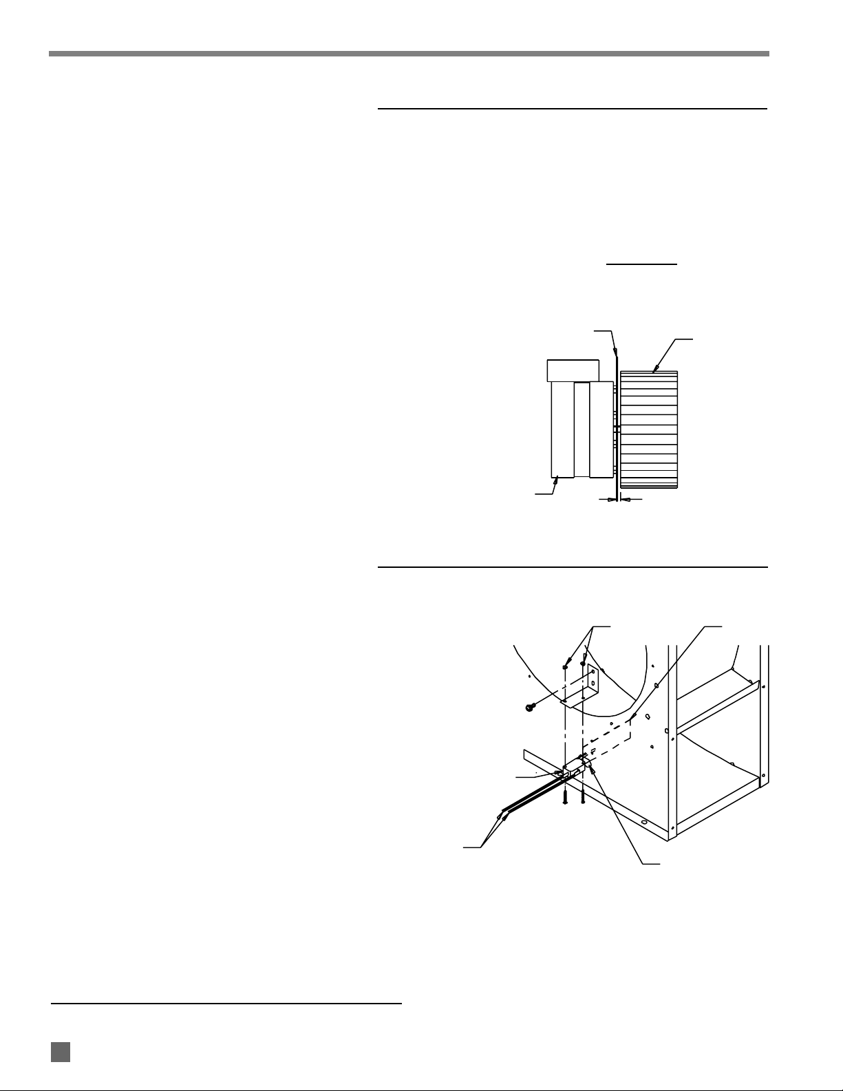
HANGING INSTRUCTIONS
1. Assemble according to the illustration and tighten all
eyebolts securely.
FIG. 2
2. Be sure heater is securely fastened and is hanging
level. (Check crosswise and lengthwise.)
3. See Fig. 3 for typical indoor installation. In any animal
confinement building, consideration must be given to
making sure the heater is located away from the
livestock so that livestock cannot knock the heater,
tear it loose from its mounting, or damage the heater
or its gas supply line in any way. Make sure you
observe and obey minimum clearance distances to
combustible materials as stated in the specification
section of this owner’s manual and on the heater
itself.
FIG. 3
10
SEDIMENT TRAP ASSEMBLY
(Optional Accessory)
EYE BOLT
NUT
FLAT WASHER
FLAT WASHER
NUT HEATER TOP
CHAIN
NIPPLE
HOSE ADAPTER
TEE
NIPPLE
CAP
TO GAS CONTROL
VALVE INLET
Assemble the tee, nipples and cap together and tighten
securely. The sediment trap assembly must always be
mounted in a vertical position. Make sure pipe thread
compound that is resistant to both L.P. gas and natural gas
is used in making all connections. Check aall cconnections ffor
gas lleaks uusing aapproved ggas lleak ddetectors.
FIG. 4

11
MANUAL SHUT-OFF VALVE, HOSE
AND REGULATOR ASSEMBLY
1. To CConnect tthe SSeries TTap PPlug TThermostat KKit:
a. Connect the power cord of the heater to the
female side of the plug on the end of the
thermostat cord.
b. Plug the male side of the series tap plug on the
thermostat cord into a three-wire (grounded)
electrical outlet within the building.
2. To CConnect tthe DDirect WWired TThermostat KKit ttotthe
Control BBox oontthe HHeater:
a. The installation and wiring of a thermostat must
be done by an electrician or someone properly
qualified.
b. The thermostat cordset must use a minimum of
18 gauge wire consisting of a hot lead, neutral
lead, and a ground lead.
c. Follow all instructions provided with the
thermostat kit.
d. The heater must be tested for proper operation
after the thermostat has been connected.
WARNING
Electrical SShock HHazard
■Disconnect the electrical supply before connecting the
thermostat to the heater.
■Failure to follow this warning can result in electrical
shock, leading to personal injury or death.
THERMOSTAT INSTALLATION
(Optional Accessories)
REGULATOR VENT
PIPING ADAPTER
VALVE, MANUAL
SHUT-OFF
NIPPLE 1/2"
REGULATOR
PIPING ADAPTER
ADAPTER
GAS HOSE
ADAPTER
SEDIMENT TRAP
TO GAS CONTROL
VALVE INLET
GAS FLOW
1. Always use approved pipe thread compound suitable
for use with L.P. gas or natural gas on the threaded
connections.
2. Assemble the components together according to the
figure. This view is to show general assembly of the
components only. The regulator must always be
mounted so its vent, regardless of location on the
regulator, is always pointed downward.
3. Tighten all connections securely.
4. Check aall cconnections ffor ggas lleaks uusing aapproved
gas lleak ddetectors.
FIG. 5
12.7 mm

12
GAS SHUT OFF KNOB
PILOT BUTTON PILOT
OFF ON
If the heater is to be shut down for cleaning, maintenance or
repair, follow steps 1 - 4. Otherwise, simply turn thermostat
to “off” or “no heat” for standard shut down.
1. Close all manual fuel supply valves.
2. With the heater lit, allow heater to burn off excess fuel
in gas supply hose.
3. Turn thermostat to “off” or “no heat” position.
4. Disconnect the heater from the electrical supply.
Shut-Down Instructions
Start-Up Instructions
Follow steps 1 - 5 on initial start-up after heater installation
by a qualified gas heater service person. For normal start-
up, simply turn thermostat above room temperature. The
heater will start.
1. Open all manual fuel supply valves and check for gas
leaks using approved leak detectors.
2. Fully depress the pilot button located on the gas
control valve while applying flame to the pilot light.
Keep the button depressed for about 30 seconds to
allow the thermocouple to warm up so the pilot stays
lit after your release the button.
ATTENTION
On new installations it may take a short period of time for the
gas to purge out any air in the pilot line before the pilot stays
lit.
3. Connect the electrical cord to an approved electrical
outlet.
4. Set the thermostat to a point above room
temperature. The heater will light. Turn the
thermostat to desired setting.
5. Do not exceed the input rating stamped on the
dataplate of the heater. Do not exceed the burner
manifold pressure stated on the dataplate. Do not
use an orifice size different than specified for the
specific input rating of this heater, fuel type
configuration and altitude.
FIG. 6

1. Have your gas supplier check all gas piping annually
for leaks or restrictions in gas lines. Also, at this time
have your gas supplier clean out the sediment trap of
any debris that may have accumulated.
2. The aappliance aarea sshall bbekkept cclear aand ffree ffrom
combustible mmaterials, ggasoline, aand oother fflammable
vapors aand lliquids.
3. Regulators can wear out and function improperly.
Have your gas supplier check the date codes on all
regulators installed and check delivery pressures to
the appliance to make sure that the regulator is
reliable.
4. Regulators must be periodically inspected to make
sure the regulator vents are not blocked. Debris,
insects, insect nests, snow, or ice on a regulator can
block vents and cause excess pressure at the
appliance.
1. Before cleaning, shut off all gas supply valves and
disconnect electrical supply.
2. The heater should have dirt or dust removed
periodically:
a. After each flock or between building re-population,
give the heater a general cleaning using
compressed air or a soft brush on its interior and
exterior. At this time, dust off the motor case to
prevent
the motor from over-heating and shutting
the heater down.
b. At least once a year, give the heater a thorough
cleaning. At this time, remove the fan and motor
assembly and brush or blow off the fan wheel,
giving attention to the individual fan blades.
Additionally, make sure the burner air inlet venturi
ports and the “throat” of the casting are free of
dust accumulation and the area between the heat
chamber top and inside case is also free of dust.
c. When washing with water, observe and obey the
Warning within these Cleaning Instructions. This
same Warning is also supplied on the heater.
WARNING
This heater may be washed only on the external case
assembly provided:
A. The heater is disconnected from the electrical supply.
B. All access panels are securely closed.
C. Water spray nozzle shall not discharge within 1.83 m
of the heater.
D. The water pressure does not exceed 3.1 BAR for 10
seconds on each side of heater.
E. The heater is not reconnected to electrical supply for
a minimum of 1 hour or until the heater is thoroughly
dry.
Improper cleaning of the heater can cause severe
personal injury or property damage due to water and/or
cleaning solution:
1. In electrical components, connections and wires
causing electrical shock or component failure.
2. On gas control components causing corrosion which
can result in gas leaks and fire or explosion from the
leak.
Clean internal components of the heater with a soft, dry
brush or cloth, or compressed air.
13
Cleaning Instructions
Maintenance Instructions
WARNING
Fire, BBurn, aand EExplosion HHazard
■This heater contains electrical and mechanical components in the gas management, safety and airflow systems.
■Such components may become inoperative or fail due to dust, dirt, wear, aging, or the corrosive atmosphere of
an animal confinement building.
■Periodic cleaning and inspection as well as proper maintenance are essential to avoid serious injury or property
damage.
Service Instructions
1. Shut off the gas supply to the heater.
2. Disconnect the heater from its electrical supply.
3. Open the case access panel on the control box end of
the heater.
4. Disconnect the motor leads.
5. Remove the screws securing the motor mounting plate
to the fan housing.
6. Pull the fan and motor assembly from the housing.
7. Loosen the square had set screw(s) on the fan wheel
with a wrench.
8. Pull the fan wheel from the motor shaft. Use a wheel
puller if necessary.
9. Remove the four (4) nuts securing the motor to the
mounting plate.
10. To replace the motor and fan, reverse the above
procedures.
NOTES: a. Fan wheel to motor mount plate spacing
must be adjusted to the clearances
specified in the table below before
tightening the fan wheel to the motor shaft.
b. Make sure that set screw(s) of the fan are
on the “flats” of motor shaft when
tightening.
Heat Output
17.6 KW 6.4 mm
65.9 KW 3.2 mm
FIG. 7
MOTOR AND FAN WHEEL ASSEMBLY
AIR PROVING SWITCH WITH PADDLE
14
MOTOR MOUNT PLATE FAN WHEEL
CLEARANCE
MOTOR
SWITCH W/PADDLE
LEADS
OBLONG HOLE
NUTS PADDLE
HOUSING SIDE PANEL
1. Shut off the gas supply to the heater.
2. Disconnect the heater from its electrical supply.
3. Open the case access panel on the control box end of
the heater.
4. Remove the two (2) sheet metal screws holding the
switch with bracket to blower housing. Remove the
assembly by turning the switch assembly 90°so the
paddle on the switch arm can be pulled through the
oblong hole on side of fan housing.
5. Disconnect the leads from the air proving switch.
6. To replace the switch, reverse the above procedure.
The replacement switch will be pre-assembled to its
mounting bracket.
IMPORTANT
Make sure you don’t bend the switch arm when installing the
replacement switch. Bending the switch arm may create
ignition problems later.
FIG. 8

1. Shut off the gas supply to heater.
2. Disconnect the heater from its electrical supply.
3. Let the appliance cool down so the pilot assembly is
cool to touch.
4. Loosen the wing screw at the pilot assembly by turning
counterclockwise. It is not necessary to remove the
screw entirely from the pilot assembly. You need to
loosen it just enough to allow you to remove the pilot
shield.
5. When loosened, pull up on the pilot shield, exposing
the pilot bracket, pilot orifice, and thermocouple.
6. Using a soft brush or compressed air, clean the pilot
stack (pop-riveted on inside of pilot shield), of dust
and dirt, paying attention to the throat of the pilot
stack and the flame spreader at the top of the stack.
7. Brush off the top of the pilot orifice making sure dust
and dirt have not plugged orifice hole. If the orifice
must be removed, use the appropriate size wrench to
loosen and remove the compression fitting and pilot
tube from the inlet of the pilot orifice. Use a wrench to
loosen and remove the pilot orifice from the pilot
bracket. Hold the orifice up to the light to see if the
hole in the orifice is clear and open. If not, blow out
with compressed air.
8. To replace the shield and the pilot orifice, reverse
above procedure.
9. Check for gas leaks.
IMPORTANT
The hole in the pilot orifice is drilled to a specific diameter to
match the fuel and gas pressure being used. Do not poke or
push sharp instruments into the hole. Doing so will enlarge
the hole, creating pilot light outage problems. Clean the
orifice only with compressed air, a soft brush, or a dry rag. If
necessary, replace the pilot orifice.
Do not use a pliers to remove the pilot orifice. Pliers will
“round off” the hex head nut on the base of the orifice,
creating difficulty in servicing at a later time. Only use a
wrench of appropriate size.
FIG. 9
PILOT LIGHT ASSEMBLY
15
SHIELD
BRACKET
WING SCREW
ORIFICE
TUBE W/NUTS
THERMOCOUPLE
STUD
BURNER CASTING

16
1. Shut off the gas supply to heater.
2. Disconnect the heater from its electrical supply.
3. Let the heater cool down so the pilot assembly is cool
to touch.
4. Loosen wing screw at pilot assembly by turning
counterclockwise. It is not necessary to remove the
screw entirely from the pilot assembly. You need to
loosen it just enough to allow you to remove the pilot
shield.
5. When loosened, pull up on the pilot shield, thereby
exposing the pilot bracket, pilot orifice, and
thermocouple.
6. To remove the thermocouple, loosen the attachment
nut (turn counterclockwise) until the nut is entirely out
of the pilot bracket. Remove thermocouple from the
pilot bracket.
7. Remove the lead connector nut threaded into the
power unit on the gas control valve.
8. To assemble, reverse above procedure.
IMPORTANT
■The thermocouple is an important safety device which
works directly with the pilot safety control valve. It
should only be replaced with the thermocouple part
number as given in the parts list for the specific model.
■When threading the thermocouple’s connector nut back
into the power unit on the gas control valve, thread the
nut in “finger tight” and “snug it” in place with a wrench.
DO NOT OVERTIGHTEN OR USE UNNECESSARY FORCE
ON THE NUT WHEN TIGHTENING. Doing so will destroy
the power unit in the gas control valve.
■Do not use a pliers when removing or replacing
thermocouple attachment nut (optional) or connector
nut. Doing so will round off the hex nuts, making
servicing difficult later on. Always use the appropriate
size wrench.
THERMOCOUPLE
FIG. 10
THERMOCOUPLE TIP
PILOT ASSEMBLY
THERMOCOUPLE LEAD
OPTIONAL ATTACHMENT NUT
THERMOCOUPLE LEAD
CONNECTOR NUT
POWER UNIT CONNECTOR
CONTACT
POWER UNIT

17
INLET PRESSURE TAP
OUTLET PRESSURE TAP
LOW PRESSURE GAUGE
5
0
10
15
20
25
30
35
GAS CONTROL VALVE
WARNING
Fire aand EExplosion HHazard
■Do not disassemble the gas control valve.
■Do not attempt to replace any components on the gas
control valve.
■The gas control valve must be placed if any physical
damage occurs to the control valve assembly.
■Failure to follow this warning will result in fire or
explosions, leading to injury or death to humans and
livestock, and building damage.
1. Brush off any accumulation of dust that may be found.
2. Check manifold gas pressure with a low pressure gas
gauge:
a. Shut off the gas supply to the heater.
b. Disconnect the heater from its electrical supply.
c. Turn the pressure tap screw at the outlet of the
valve counterclockwise a minimum of one full turn.
d. Connect a low pressure gas gauge to the pressure
tap.
e. Open the fuel supply and reconnect the heater to
electrical supply.
f. Start the heater.
g. When heater lights, the gas gauge will read 25
MBAR for LP vapor or 10 MBAR for natural gas
pressure. This pressure is the flowing gas pressure
necessary for the heater to deliver its maximum
output. If the gauge does not indicate proper
manifold pressure, check the inlet pressure to the
gas control valve. Maximum and minimum
acceptable inlet pressures to the gas control valve
are shown in the heater specifications table and
also on the heater’s dataplate. The inlet pressure
may need adjustment as necessary to achieve
proper outlet pressure. Inlet pressure is checked
in the same manner as outlet pressure.
h. After pressures have been checked, shut off gas
supply and electrical supply to the heater, remove
the gauge, and tighten the pressure tap securely.
Open the gas supply and reconnect the heater to is
electrical supply.
FIG. 11

The high limit switches should be tested a minimum of once
per year when the heater is given a thorough cleaning.
1. Disconnect the heater from its electrical supply.
2. Remove the high limit switch from the heat chamber.
3. Holding the switch by one of its mounting legs, apply a
small flame only to the sensing portion on the back of
the switch. Be ccareful nnot ttommelt tthe pplastic hhousing
of tthe sswitch wwhen cconducting tthis ttest.
4. Within a minute, you should hear a “pop” coming from
the switch, which indicates the contacts of the switch
have opened.
5. Allow the switch cool down for about a minute before
firmly pressing the reset button on the switch.
6. Check for electrical continuity across the switch
terminals to make sure the contacts have closed.
7. Reinstall the switch back into the heater. Reconnect
the heater to its electrical supply. Start the heater and
check for proper operation.
FIG. 12
TESTING THE MANUAL RESET HIGH LIMIT SWITCH
18
WARNING
Fire HHazard
■Do not operate the appliance with the high limit switch
bypassed.
■Operating the heater bypassed high limit switch may
lead to overheating, possibly resulting in a fire, with
subsequent damage to the heater, building damage, or
loss of livestock.
RESET BUTTON
SENSING
SURFACE
TERMINAL
FLAME
MOUNTING
LEG

19
READ THIS ENTIRE SECTION BEFORE
BEGINNING TO TROUBLESHOOT PROBLEMS.
The following troubleshooting guide provides systematic
procedures for isolating equipment problems. This guide is
intended for use by a QUALIFIED GAS HEATER SERVICE
PERSON. DO NNOT AATTEMPT TTOSSERVICE TTHESE HHEATERS
UNLESS YYOU HHAVE BBEEN PPROPERLY TTRAINED.
TEST EEQUIPMENT RREQUIRED
The following pieces of test equipment will be required to
troubleshoot this system with minimal time and effort.
• Digital MMultimeter - for measuring AC and DC voltage and
resistance.
• Thermocouple DDiagnostic KKit - (PSI Part No. 550-08506)
When used with a standard digital multimeter, this kit
allows testing of the thermocouple and electromagnetic
power unit strength of the pilot safety gas control valves.
• Low PPressure GGauge - for checking inlet and manifold
pressures at the gas control valve against dataplate rating.
■Visually inspect equipment for apparent damage.
■Check all hoses for abrasion and wear. Replace any
that are suspect.
■Make sure heater is properly installed and meets
minimum clearances to nearest combustible materials.
(Refer to dataplate on heater.)
■Check all wiring for loose connections and worn
insulation.
To effectively use these flow charts, you must first identify
the problem. The problems are numbered sequentially,
along with a brief explanation of each problem. Start at the
“diamond” closest to the identified problem and proceed
with each step, performing whatever tests are suggested.
After each step or test, the guide will direct the service
person to the next logical step based on the outcome of the
previous check.
Components should be replaced only after each step has
been completed and replacement is suggested in the flow
chart.
The problems are listed below along with the page number
on which you may find the flow chart for the specific problem.
Problem Description Page
1 Pilot will not light . . . . . . . . . . . . . . . . . . . . . . . 20
2 Pilot will not stay lit when pilot control
button is released . . . . . . . . . . . . . . . . . . . . . . 21
3 Motor runs. Burner does not light with
pilot light lit . . . . . . . . . . . . . . . . . . . . . . . . . . . . 22
4 Motor does not run, heater does not light
with pilot light lit . . . . . . . . . . . . . . . . . . . . . . . . 23
5 Main burner cycles on and off repetitively.
Pilot stays lit . . . . . . . . . . . . . . . . . . . . . . . . . . . 24
6 Pilot will not stay lit when main burner and
blower are operating . . . . . . . . . . . . . . . . . . . . 24
7 High limit switch is open . . . . . . . . . . . . . . . . . 25
8 Burner does not shut off . . . . . . . . . . . . . . . . . 26
9 Flame “lifting” off of burner . . . . . . . . . . . . . . 26
10 Burner flame drops out after 10 - 15
minutes of operation . . . . . . . . . . . . . . . . . . . . 26
11 Gas control valve “chatters” . . . . . . . . . . . . . . 27
12 Motor “hums” . . . . . . . . . . . . . . . . . . . . . . . . . . 27
Troubleshooting Guide
WARNING
Electrical SShock aand BBurn HHazard
■Troubleshooting this system may require operating the
unit with line voltage present and gas on. Use extreme
caution when working on the heater.
■Failure to follow this warning may result in property
damage, personal injury or death.

20
Problem 11
Pilot wwill
not llight.
Is
LP gas
container full?
Yes
No
Yes Yes
Yes Yes
Are all fuel
supply valves
open?
Remove these
components and
blow out with
compressed air.
Fill container if low. Open all supply valves. Is the
pilot control
button fully
depressed?
Replace pilot
orifice.
Is there air in
the gas line?
No No
Fully depress the
pilot button.
No No No
Yes Depress pilot
button to bleed
off the air until
pilot lights.
(Normally 30 -
45 seconds.)
Check for proper fuel
pressure to inlet of
heater. Adjust as
necessary.
Is the
correct pilot
orifice installed
for the fuel being
used?
Is
there a
restriction in gas
supply hose, pilot
tube or pilot
orifice?
Other manuals for 1450 Series
4
This manual suits for next models
2
Table of contents
Other PSI Heater manuals


Popular Heater manuals by other brands

HeatStar
HeatStar HS115TC Operating instructions and owner's manual

Etherma
Etherma LAVA DESK 120 Installation and usage instructions

Sawo
Sawo TH2-30Ni2-WL manual

Olimpia splendid
Olimpia splendid Vapore Alogena Instructions for installation, use and maintenance

Somogyi
Somogyi home FK 35/BK instruction manual

Gasmate
Gasmate AREA AH1063 Installation, operation and maintenance instructions


