Rheem Raypak Hi Delta 302C User manual

Eective: 03-05-21
Replaces: 02-27-13
P/N 241275 Rev. 11
INSTALLATION AND OPERATION
MANUAL
Cold Water Start & Cold Water Run
IMPORTANT SAFETY INSTRUCTIONS. READ AND FOLLOW ALL
INSTRUCTION. SAVE THESE INSTRUCTIONS.
NOTE: The instructions in this manual are for the use of qualied individuals specially trained
and experienced in the installation and maintenance of this type of equipment and related system
components. Installation and service personnel are required by some states to be licensed. Persons
not qualied shall not attempt to install, service, or maintain this equipment.
This manual should be maintained in legible condition and kept adjacent to the variable speed pump or in a safe
place for future use.
For Hi Delta, MVB & Raytherm Heaters & Boilers

2
Revision 11 reects the following changes:
Reformatted document to InDesign. Two introductory paragraphs added to section "Cold Water Start" on page 5. Caution revised on
page 5. Revised rst note on page 9. Figure 12 revised on page 9. Caution revised on page 9. Figure 21 revised on page 21. Obsolete
text and gures relating to Elodrive removed. Obsolete text and gures related to Hitachi Inverters removed. "Illustrated Parts List
section" added on page 32.

3
CONTENTS
1. WARNINGS ............................................................ 4
Pay Attention to these Terms .................................. 4
2. GENERAL SAFETY................................................ 5
Time/Temperature Relationships in Scalds ............. 5
3. COLD WATER START ........................................... 5
Installation ............................................................... 6
Check the Power Source ........................................ 6
Mounting the Control Box........................................ 6
Installing the Temperature Sensor .......................... 6
Connecting the Valve Assembly .............................. 6
Connecting Power to the Controller ........................ 8
Connecting Boiler to Cold Water Start ................... 8
Operation ................................................................8
Cold Start Sequence of Operation .......................... 9
Troubleshooting ....................................................10
Mounting the Actuator to the Valve ....................... 10
Verifying Ball Position............................................ 10
Installing the Three-Way Valve .............................. 11
High Pressure Tab ................................................. 11
Cold Water Start Troubleshooting Guide .............. 12
Typical Cold Water Start Piping ...........................13
Wiring Diagrams–Cold Water Start ....................... 14
Heater Interface Wiring ......................................... 15
4. COLD WATER START-MULTIPLE BOILER...... 16
Materials Included ................................................. 16
Installation ............................................................. 16
Mounting the Control Boxes ..................................16
Installing the Temperature Sensor ........................ 16
Installing the Three-way Valve .............................. 16
Connecting Power to the Controller ...................... 16
Connecting the CWS Control to the Multi-Boiler
Interlock Box ................................................ 16
Connecting the Boiler to the CWS Multi-Boiler
Interlock ....................................................... 16
Actuator to Valve Orientation ................................ 16
Three-Way Valve Ball Orientation ......................... 17
Valve Installation ................................................... 17
4-Inch Valve Orientation ........................................ 17
Connecting the Actuator ........................................ 18
Typical Cold Water Start Multiple Boiler Piping .... 19
Wiring Diagram ..................................................... 20
5. COLD WATER RUN.............................................. 21
Purpose ................................................................. 21
Typical Cold Water Run Applications .................... 21
CWR vs. CWS .......................................................21
Installation ............................................................. 21
Installation Codes.................................................. 21
Mounting the Control Box...................................... 21
Injector & Heater Pump Comparison .................... 22
Check the Power Source ...................................... 24
Injector Pump Wiring ............................................. 24
Injection Pump Cover Installation.......................... 25
Typical Cold Water Run Piping - Heating Apps ..... 27
Typical Cold Water Run Piping - Pool Apps .......... 27
Operation ..............................................................28
Cold Run Sequence of Operation ......................... 28
Cold Water Run Troubleshooting Guide ............... 29
Wiring Diagrams ....................................................30
6. REPLACEMENT PARTS ..................................... 31
7. ILLUSTRATED PARTS LISTS ............................ 32

4
1. WARNINGS
Pay Attention to these Terms
ADANGER Indicates the presence of immediate hazards which will cause severe personal injury, death or
substantial property damage if ignored.
AWARNING Indicates the presence of hazards or unsafe practices which could cause severe personal injury,
death or substantial property damage if ignored.
ACAUTION Indicates the presence of hazards or unsafe practices which could cause minor personal injury or
product or property damage if ignored.
CAUTION CAUTION used without the warning alert symbol indicates a potentially hazardous condition
which could cause minor personal injury or product or property damage if ignored.
NOTE Indicates special instructions on installation, operation, or maintenance which are important but
not related to personal injury hazards.
NOTE: Minimum 18 AWG, 105°C, stranded wire must
be used for all low-voltage (less than 30 volts) external
connections to the unit. Solid conductors should not
be used because they can cause excessive tension on
contact points. Install conduit as appropriate. All high-
voltage wires must be the same size (105°C, stranded
wire) as the ones on the unit or larger.
NOTE: Piping diagrams in this manual are not intended
to replace an engineered piping system.
NOTE: Consult the factory for units with a 30-pound
pressure relief valve (PRV).

5
2. GENERAL SAFETY
To meet commercial hot water use needs, the high-limit
safety control on this water heater is adjustable up to
210°F (99°C). However, water temperatures over 125°F
(51.7°C) can cause instant severe burns or death from
scalds. When supplying general purpose hot water, the
recommended initial setting for the temperature control is
125°F (51.7°C).
Safety and energy conservation are factors to be
considered when setting the water temperature on the
thermostat. The most energy-ecient operation will result
when the temperature setting is the lowest that satises
the needs of the application.
Water temperature over 125°F (51.7°C) can cause instant
severe burns or death from scalds. Children, disabled and
elderly are at highest risk of being scalded.
• Feel water before bathing or showering.
• Temperature limiting valves are available.
NOTE: When this water heater is supplying
general-purpose hot water for use by individuals, a
thermostatically controlled mixing valve for reducing
point-of-use water temperature is recommended to
reduce the risk of scald injury. Contact a licensed plumber
or the local plumbing authority for further information.
Maximum water temperatures occur just after the
heater’s burner(s) have shut-o. To determine the water
temperature being delivered, turn on a hot water faucet
and place a thermometer in the hot water stream and read
the thermometer.
Water temperature over 125°F can
cause instant severe burns or death
from scalds.
Children, disabled, and elderly are
at highest risk of being scalded.
See instruction manual before set-
ting temperature at water heater.
Feel water before bathing or show-
ering.
Temperature limiting valves are
available, see manual.
Time/Temperature Relationships in
Scalds
The following chart details the relationship of water
temperature and time with regard to scald injury and
may be used as a guide in determining the safest water
temperature for your applications.
Water Temp. Time to Produce Serious Burns
120ºF (48.9°C) More than 5-Minutes
125ºF (51.7°C) 1-1/2 to 2-Minutes
130ºF (54.4°C) About 30-Seconds
135ºF (57.2°C) About 10-Seconds
140ºF (60.0°C) About 5-Seconds
145ºF (62.8°C) About 3-Seconds
150ºF (65.6°C) About 1-1/2-Seconds
155ºF (68.3°C) About 1-Second
Table courtesy of the Shriner's Burn Institute
Table A. Time to Produce Serious Burn
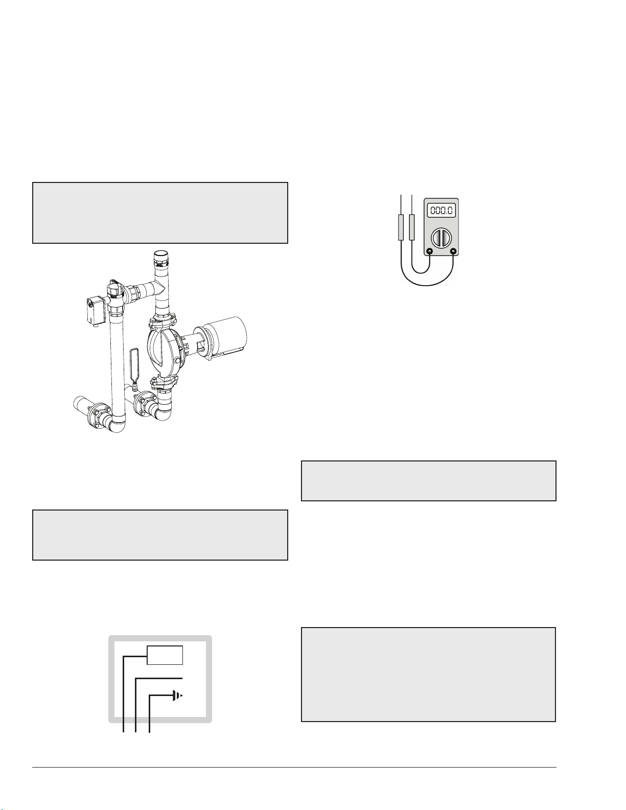
3. COLD WATER START
It is commonly known that prolonged internal condensation
will dramatically shorten the life of standard eciency
boilers. While Raypak boilers can operate without harmful
condensation at lower inlet water temperatures than the
competition, there are still applications that require reliable
protection against harmful condensation caused by
frequent, extended, cold water start-ups. Raypak's Cold
Water Start protection system utilizes a proportional three-
way valve to bypass water from the boiler outlet to the inlet
during start-up, when the system return water temperature
is below the minimum acceptable level.
This approach:
• continuously monitors and adjusts inlet water
temperature to prevent condensation.
• regulates the minimum inlet water temperature
during system start-up.
• activates an alarm and/or shuts down the boiler if the
minimum inlet water temperature is not achieved.
• eliminates jobsite setup with proprietary self-tuning
controller and system-matched components.
• allows high-temperature system operation without
cycling on the high-limit.
ACAUTION: The Cold Water Start package is ONLY
supported for closed-loop hydronic applications. Do not
use for domestic hot water systems, or pool systems.

6
Before beginning the installation, it’s important to rst
inspect the system and determine what materials you will
need. Some parts are included with the controller while
others you will need to provide.
• 1 Control Box
• 1 Temperature Sensor
• 1 Cover
• 1 Valve assembly with actuator (Shipped separately).
• Wiring and mounting hardware (Provided by installer)
NOTE: After testing, the factory may ship the piping
assembly disassembled and attached to the heater
pallet. This is done to avoid shipping damage and it must
be reassembled on the jobsite. Use Figure 1 to assist in
reassembling the piping.
Figure 1. Cold Water Start Assembly
Installation
Check the Power Source
AWARNING: Using a multi-meter, check the following
voltages at the breaker panel prior to connecting any
equipment. Make sure proper polarity is followed and
house ground is proven.
Check the power source:
• AC = 108VAC Minimum, 132VAC MAX
• AB = 108VAC Minimum, 132VAC MAX
• BC = <1VAC Maximum
CIRCUIT
BREAKER
WHITE
GROUND
BLACK
GREEN
A B C
Figure 2. Wiring Connections
Mounting the Control Box
The control box should be mounted on the side of the
heater to which the system piping and valve assembly are
to be attached as shown in Figure 4 through Figure 8. The
controller should be mounted so as to provide maximum
support by using the mounting holes provided on the base
of the controller to the side center brace on the heater. On
MVB and Hi Delta models, locating dimples are provided
for ease of drilling the mounting holes. You will need to
drill mounting holes through the heater side panel for the
routing of wiring and the sensor.
Figure 3. Multi-meter
Installing the Temperature Sensor
Avoid routing wiring on or near other electrical wires,
conduit, motors, spark igniters or other sources of high
intermittent voltage or current. The sensor should be
placed in the dry well on the inlet header, or as indicated
in the piping for multiple boilers, as shown on page 18.
Ensure it is installed using thermal paste (eld supplied)
and that it is held rmly at the bottom of the well.
Connecting the Valve Assembly
CAUTION: Miswiring the actuator may cause
unwarrantable damage. Verify the wire colors against
the actuator make and model.
Connect the valve assembly into the bypass piping. The
branch (port B) is connected to the crossover pipe (bypass
between inlet and outlet). The actuator tail stock should
be oriented to point down. Refer to the Actuator to Valve
Orientation section.
Route wiring from the valve to the controller through one
of the bottom panel conduit knockouts to TB2. Refer to
the wiring diagram provided on the inside of the controller
cover assembly.
ACAUTION: Install the foil-faced insulation on the
inside of the rear panel of MVB heaters as indicated in
Figure 8. Use spray adhesive or high-temp foil tape to
attach the insulation. Ensure that the foil faces the heat
exchanger assembly. Failure to install this insulation
as directed can cause overheating of the components
and any resulting damage will not be covered under
warranty.

7
THREE-WAY VALVE
VALVE ACTUATOR
CONTROL
BOX
FRONT OF
HEATER
X
Y
Z
Figure 4. Component Locations—Hi Delta
Models X Y Z
302C-902C 7ʺ (178 mm) 2ʺ (51 mm 1-9/16ʺ (40 mm)
992C-2342C 13-1/4ʺ (327 mm) 1-5/16ʺ (34 mm) 6-5/8ʺ (168 mm)
LEFT
SIDE
CONTROL BOX
MTG PANEL
11/16" (17 mm)
7-1/4"
(184 mm)
11-1/8"
(283 mm)
Figure 5. Component Locations—Raytherm Models
514–824
11-1/8"
(283 mm)
10-5/16"
(262 mm)
CONTROL
BOX MTG
PANEL
1"
(51 mm)
Figure 6. Component Locations—Raytherm Models
926–1826
CONTROL
BOX MTG
PANEL
22"
(559 mm)
7-5/8"
(194 mm)
1-1/2"
(38 mm)
Figure 7. Component Locations—Raytherm Models
2100–4001

8
Figure 8. Component Locations—MVB
CONTROL
BOX
9-9/16"
(243 mm)
1-3/4"
(44 mm)
5/16"
(8 mm)
INSTALL
INSULATION
ON INSIDE OF
REAR PANEL
Connecting Power to the Controller
Connect power from the 120VAC power input of the heater
to the controller power inputs Terminal Block (TB1). This is
accomplished by connecting wiring from the control box to
the heater 120VAC power input connections. Refer to the
heater wiring diagrams.
Connecting Boiler to Cold Water Start
The installer must provide ve 18AWG stranded wires
between the heater and the controller terminal block.
Wiring is to be run in separate conduit from line voltage to
ensure proper operation. Refer to the diagrams on page
15 for connection points depending on the Raypak
product being used.
Operation
Verify the following upon a CALL FOR HEAT signal from
the heater:
1. CALL FOR HEAT: LED on PCB illuminates GREEN.
2. START UP MODE: LED on PCB illuminates
YELLOW. It should go out in less than 7-minutes, as
the boiler inlet temperature approaches the setpoint
temperature.
3. The “ACTUATOR” should be in the fully open position
or move to the fully open position if not already
there. (Actuator and ball rotated to the at-rest CCW
position).
4. If the control is operating properly, the “START UP
MODE” LED should go out in less than 7-minutes.
At this point, the inlet water temperature should be
stable at a temperature between 105°F (40.5ºC)
and 120°F (48.9ºC) corresponding to the Setpoint
Pot setting on the PCB. The actuator should have
stopped moving.
RESET SWITCH*
*The reset switch may be located on the front control panel on some
MVB models.
Figure 9. Location of TB1 in Control Box
SETPOINT
POT
CALL FOR HEAT
START UP MODE
INLET TEMP ERROR
SENSOR OUT OF RANGE
Figure 10. Control PCB

9
NOTE: The minimum inlet water temperature to the
heater to prevent condensate is 105°F (40.5ºC) on heaters
with an eciency of 85% or less, and 120°F (48.9ºC) on
86% eciency heaters. Ensure that during operation the
Setpoint Pot is adjusted properly.
NOTE: If a “DIP” switch is provided on the control PCB,
verify that the switch settings are: 1 = OFF, 2 = ON, 3 =
OFF.
NOTE: The heater will lockout and shut down if the
setpoint on the inlet temperature is not achieved within
7-minutes from a call for heat.
Cold Start Sequence of Operation
1. 120VAC to heater sends 120VAC to Cold Start control
on terminal block 1.
2. 120/24VAC transformer and 120VAC-12VDC
converter are powered.
3. 120/24VAC transformer outputs 24VAC to pin 2 of
terminal block 2.
4. 24VAC leaves pin 2 of terminal block 2 and goes to
the modulating three-way valve on the 20-30VAC
lead, and to the NO contacts of the SPST relay
located in the cold start control panel.
5. 120VAC-12VDC converter outputs 12VDC to the
common terminal of the reset switch, located on the
bottom of the cold start control panel.
6. The 12VDC signal crosses over the reset switch and
goes to Terminal FS on the cold start circuit board.
7. Cold start control is now in standby until a Call for
Heat occurs at heater.
8. The heater outputs 24VAC to terminal 4 of terminal
block 3 located in Cold Start controller to indicate a
CFH from the heater.
9. Terminal 4 of TB 3 sends 24VAC to the coil of the
SPST relay located in the cold start control panel.
10. The SPST relay coil is energized and closes the
contacts allowing 24VAC to energize the CFH
terminal on the cold start circuit board.
a. A two-second delay occurs from the CFH signal
to the output of power from terminal MC of the
cold start circuit board.
11. 24VAC is sent from terminal 2 of terminal block 3 to
the NO contacts of the DPST relay located in the cold
start control panel.
12. After the two-second delay on the cold start circuit
board, pin MC outputs a 24VAC signal to the coil of
the DPST relay located in the cold start control panel.
13. The DPST relay coil energizes and closes the NO
contacts.
14. Once the NO contacts of the DPST close, the heater
24VAC is sent back to the heater to complete the
circuit (pin 3 of terminal block 3) and the interlock
circuit (pin 1 & 2 of terminal block 3) allowing the
heater to fire.
15. Pin FR on the TVC board outputs 10VDC to the
modulating three-way valve actuator to drive it fully
open for 2-minutes waiting for the heater to reach full
fire.
16. After the 2-minute delay the 10VDC output signal
from pin FR reduces to approximately 8VDC.
17. The output signal continues to vary depending on the
heater inlet temperature.
The DIP switches on the three-way valve actuator must be
set as indicated in Figure 11 below.
DIP SWITCH SETTINGS
FOR 3-WAY ACTUATOR
VDC
0-10
DA
FIXED
~
mA
2-10
RA
AUTO
6-9
SWITCH MUST BE IN THIS POSITION
TURN CLOCKWISE TO FURTHEST STOP
MODE SELECTION SWITCH
DIRECT ACTING, ON INCREASING SIGNAL
Figure 11. Set Dip Switch Settings - Actuator
NOTE:
THIS
SIDE
MUST
FACE
AWAY
FROM
VALVE
OPERATING
ROTATION DIRECTION
Figure 12. Actuator Shown in Full System Flow Position
CAUTION: For outdoor installations, the factory-
supplied weatherproof cover must be used.

10
Troubleshooting
Check your power source using a Volt-Ohm meter; check
the following voltages at TB1 terminal block:
TB1-1 to TB1-2 = 108VAC Minimum, 132VAC Maximum
TB1-1 to TB1-3 = 108VAC Minimum, 132VAC Maximum
TB1-2 to TB1-3 = Must be less than 0.6VAC
IF CALL FOR HEAT LED does not illuminate when the
heater has a CFH signal, check for 24VAC between pins 4
and 5 of TB3 on the cold start control. If voltage is present,
check wiring using the wiring diagram. If voltage is not
present, the problem exists in the heater.
IF VALVE DOES NOT MOVE: Check for voltage out at
TB2-1: Should be a 1 to 10VDC output to the actuator
valve. If no voltage is present, check for voltage at pin FS
on the control board, there should be a 12VDC signal. If
the 12VDC signal is not present, verify that the converter
is wired correctly using the wiring diagram.
IF INLET TEMP ERROR is illuminated: The setpoint
temperature has not been reached within the 7-minute
time period.
• Push the Reset Switch, see Figure 9, or remove
power and watch for proper operation.
• Check pump sizing and valve/piping sizing and
correct as necessary.
IF SENSOR OUT OF RANGE LED is illuminated: The
sensor may have a short or open circuit.
• Press and release the Reset Switch (see Figure 9)
and watch for proper operation.
• Replace sensor.
• Check wiring using wiring diagram.
Mounting the Actuator to the Valve
When mounting the actuator to the valve, ensure that
the valve stem is oriented with the machined at notch
positioned parallel to the “A” and “AB” ports as shown in
Figure 13.
All actuators used by Raypak include the “spring return”
safety feature. This means that upon loss of power during
operation, the valve automatically rotates back to the full
system ow position avoiding high-limit lockouts or other
issues.
A
B
AB FLOW
FLAT NOTCH
Figure 13. Orient Notch Parallel with “A” and “AB” Ports
Verifying Ball Position
All eld-installed valves must have the ball properly
positioned. Occasionally dierences occur from the
manufacturer of the valve body. The square stem that the
drive linkage attaches to should have a machined notch to
verify ball position, however on occasion it is not there. To
properly orient the ball follow these instructions PRIOR to
installation into your plumbing system.
• Remove the actuator and base from the valve body.
• With port “AB” facing you, rotate the valve stem
approximately 45 degrees clockwise. You must see
two port openings if the ball is correctly oriented.
• If you do not see two openings at this point, continue
rotating the stem and ball until you do.
• Once you can see two openings, STOP, as shown
in Figure 14. Then rotate the stem counterclockwise
until only one opening remains e.g. you can see
completely through the valve (through ports A and
AB).
Now the ball is correctly oriented inside of the valve body.
Reassemble the valve, base and actuator, and then install
the assembly into your piping system as indicated in this
manual.

11
PORT AB
Figure 14. Verifying Ball Position
Figure 15. Recommended Orientation of Actuator
Figure 16. Incorrect Orientation of Actuator
Installing the Three-Way Valve
When threading any pipe into the ports of the three-way
valve, a backing wrench MUST be employed. You must
capture the valve body with a secondary wrench to avoid
damaging the internal seals. Valve bodies leaking from
improper installation are non-warrantable.
High Pressure Tab
Located between the valve body and the actuator mounting
bracket, is a yellow tab labeled “High Pressure” see Figure
17. This is for maintenance of the valve only.
If the valve stem begins leaking beneath the yellow tab
the internal packing material must be replaced. The “High
Pressure” tab is held on with two screws located under the
mounting bracket.
To replace the packing material, all water pressure must
be removed from the valve assembly and the assembly
must be isolated from the system water. Then remove the
actuator and bracket, then remove the two screws holding
the “High Pressure” tab in place.
At this point the packing material can be removed and
replaced just like any other valve assembly. The packing
material is not available from Raypak.
HIGH
PRESSURE
TAB
Figure 17. High Pressure Tab

12
Ste
p
9
Ste
p
8
Ste
p
10
Step 1
Step 2
Step 3
Step 4
Step 5
Step 6
Step 7
Is there a Call For
Heat at the heate
r
?
Are the 120/24VAC
transformer and 120VAC-
12VDC inverter in the cold
start controller powered?
Replace 120VAC-12VDC
inverter or correct wiring.
Does the cold start 12VDC inverter
output 12VDC to the reset switch
and to common pin FS of the cold
start circuit board?
Does the cold start 120/24VAC
transformer output 24VAC to pin
2 of TB2 and the valve actuator?
Replace transformer or
correct the wiring
Replace circuit board
Are the terminals 1-4 of TB3
connected to N.O. contacts of
DPDT relay?
Does cold start DPDT
relay coil receive 24VAC
from MC on circuit board?
Are terminals 1-4 of TB3
correctly connected back
to the heater?
Call our Technical Service Department
1-805-278-5300
NO Verify 120VAC at separate
circuit breaker and correct.
YES
Does TB1 of cold start
controller have 120
VAC?
Heater is in standby mode
Correct wiring to
match wiring diagram
YES NO
NO
YES
YES
NO
NO
NO
YES
YES
NO
The unit is okay
YES
NO
YES
Correct wiring
Is the actuator modulating after
2-1/2 minutes?
NO
Correct wiring
YES
Is the heater tripping the high
limit?
YES
NO
Verify actuator is set to reverse acting
and three-way valve is not installed
backwards.
2” & 2-1/2” valve must
rotate CW on decreasing 0-
10VDC signal. 4” valve will
rotate CCW.
YES
Correct settings or valve
orientation
NO
Is 24VAC present at CFH
terminal on cold start circuit
board?
Check and verify 24VAC between pin 4 and 5
of TB3 in cold start controller and correct.
Is 0-10VDC present at
connection FR of cold start
circuit board?
NO Replace cold start circuit board
YES
NO
YES
Does cold start circuit board lock-out on
“Sensor out of Range”?
NO
YES
Is sensor resistance correct?
YES
NO
Replace sensor
Is system water
temperature
below 32ºF?
NO
YES
Does the reset switch send
12VDC to terminal FS on the
cold start circuit board?
NO
YES
Cold Water Start Troubleshooting Guide

13
NOTES:
1. LOCATE UNIONS TO FACILITATE SERVICING OF PLUMBING SIDE.
2. PLUMB SWING CHECK VALVE IN GRAVITY-CLOSED POSITION.
3. PIPE ALL RELIEF VALVES TO DRAIN, OR AS LOCAL CODES REQUIRE
.
4. BUFFER TANK REQUIRED WHEN WATER VOLUME IN BOILER LOOP
IS NOT ADEQUATE TO PROVIDE STABLE TEMPERATURE CONTROL.
CONSULT FACTORY FOR TANK SIZING.
5. SYSTEM FLOW MUST EXCEED HEATER FLOW AT ALL TIMES.
Typical Cold Water Start Piping

14
Wiring Diagrams–Cold Water Start

15
HEATER INTERFACE WIRING FOR CWS OR CWR
CWS/CWR
CONTROL OR
MUL
TIPLE BOILER
INTERFACE
CWS/CWR
CONTROL OR
MULTIPLE BOILER
INTERFACE
CWS/CWR
CONTROL OR
MULTIPLE BOILER
INTERFACE
Heater Interface Wiring

16
4. COLD WATER START-
MULTIPLE BOILER
(Maximum 4 Boilers)
Materials Included
• 1 Cold Start Control Box
• 1 Multi-Boiler Interlock Box
• 1 Water Sensor & Well
• 1 Three-way Diverting Valve assembly with Actuator
NOTE: Flanges, bolts and gaskets for anged valves
supplied by others.
Installation
Mounting the Control Boxes
Cold Start Control and Multi-Boiler Interlock should be
mounted in such a manner as to allow for easy access for
wiring of the boiler interlock connections.
Installing the Temperature Sensor
Temperature sensor to be installed in a drywell with thermal
paste at the location indicated in the diagram on page 21
to ensure proper operation of the control system. Installer
must ensure the drywell extends at least 2 inches into the
water ow path. Sensor wiring must be run in separate
conduit from line voltage and should be a minimum of 18
AWG shielded cable. Refer to "Wiring Diagram" on page
19 for wiring information.
Installing the Three-way Valve
Install three-way diverting valve into common boiler piping
manifold as shown in the diagram on page 18. Boiler
common outlets to be connected at port AB. Discharge to
system from port A with bypass port being port B. Common
pipe sizing may be larger than three-way valve port
connections requiring the use of increasers for installation
(see Table B for valve sizing). It is recommended that three-
way valve be installed as near the main system piping as
is feasible. Route control wiring in separate conduit to the
Cold Water Start control box and wire as shown in the
diagram on page 19.
Connecting Power to the Controller
Installer to provide a dedicated 120V circuit with local
disconnect to the Cold Water Start Control. Refer to wiring
Figure 9 for detailed instruction.
Connecting the CWS Control to the
Multi-Boiler Interlock Box
Installer to provide four 18AWG stranded wires between
pins 7-10 on the Cold Start Control and 7-10 on the Multi-
Boiler Interlock as shown in "Wiring Diagram" on page
19. Do not use solid-core wire when wiring any portion
of the Cold Start Multi-Boiler system.
Connecting the Boiler to the CWS
Multi-Boiler Interlock
Installer to provide ve 18AWG stranded wires between
each boiler and Multi-Boiler Interlock box. Wiring to be
run in separate conduit from line voltage to ensure proper
operation. Refer to "Wiring Diagram" on page 19 for
connection points depending on Raypak product being
used.
Connecting the Actuator
The 4-inch valve is shipped loose, and must be eld wired.
Connect the actuator leads to the Cold Water Start control
panel, as indicated in the wiring diagram on page 14.
The actuator for the 4" valves rotates opposite to the
direction of the smaller actuators.
Actuator to Valve Orientation
Install the actuator so that the tail is pointing horizontally
as shown in "Valve Orientation (Actuator)" on page 17 is
pointing down. DO NOT mount it so that the tail is pointing
Total Load
(MBTU) Valve Size
Minimum
Pipe Size
in. (mm)
Cv Flow Rate
GPM (lpm)
Valve
Pressure Drop
Ft. hd. (kPa)
∆T @ Max
Size
ºF (ºC)
∆T @ Min.
Size
ºF (ºC)
Order No.
600-1000 2" NPT 2 (51) 57 70 (265) 3.5 (10.5) 22 (12.2) 14.4 (8.0) 012228
1001-1800 2.5" NPT 2.5 (63) 74 100 (379) 4.2 (12.6) 30.2 (16.8) 16.8 (9.3) 012229
1801-2600 2.5" NPT 3 (76) 100 150 (568) 5.2 (15.5) 29.1 (16.2) 20.1 (11.2) 012230
2601-4000 4" FLG* 4 (102) 152 220 (833) 4.8 (14.3) 30.5 (17.1) 22.9 12.7) 012231
4001-6000 4" FLG* 4 (102) 254 330 (1249) 3.9 (11.7) 30.5 (17.1) 20.3 (11.3) 012232
6001-8000 4" FLG* 6 (152) 327 440 (1666) 4.2 (12.2) 30.5 (17.1) 22.5 (12.5) 012233
Standard boiler pump options offered by Raypak may NOT be appropriate for these applications.
*CAUTION: Approved for closed-loop systems only.
Table B. Valve Sizing Chart

17
up as shown in Figure 16. Doing so will allow water and
debris to collect in the cup where the wiring exits the
actuator, potentially causing damage.
Three-Way Valve Ball Orientation
The ball orientation must be veried prior to mounting the
anged valve into the piping system. With the anged four-
inch valve it is a fairly simple procedure. Do not use the
groove on the end of the drive linkage to verify.
First, remove the actuator by removing the wing-nut
underneath the mount bracket near the tail. Second,
loosen the locking bolt on top of the actuator that clamps
to the drive linkage.
Once this has been done, remove the actuator by lifting
straight o the drive linkage shaft.
Now the ball position must be veried. Using pliers,
grasp the base of the drive linkage. While looking into
port AB, rotate the drive linkage counterclockwise about
45 degrees. See Figure 18. You should see two partial
openings similar to Figure 14.
Figure 18. Rotating the Drive Linkage
If you do not see the two partial openings after 45 degrees
of rotation, continue rotating until you do. Once you see
the two partial openings, STOP. Now rotate the shaft in
the reverse direction (clockwise) until you can see straight
through to valve from port AB to port A.
Reinstall the actuator and bracket assembly in reverse
order, and ensure that the ball assembly is properly
oriented. Mount the anged valve into your piping system
in accordance with this manual.
Valve Installation
To properly install this valve, port “AB” must be connected
to the combined outlet of the heater(s); and port “B” must
be attached to the bypass between the combined inlet and
the combined outlet, as shown on page 18. The valve
body has the port designators cast into the drive linkage
housing. See Figure 19.
PORT AB
Figure 19. Valve Orientation
4-Inch Valve Orientation
The valve must be installed so that the combined boiler
outlets enter through Port “AB” (See Figure 20). Port “B” is
the bypass port and port “A” is the return to the system (port
designations are cast into the stem of the valve body). The
valve body should be installed so that the actuator input
shaft is in the vertical or horizontal position. The Actuator
stem should never be hanging downward.
As shipped from the factory, the actuator is in the horizontal
position when the valve is installed as shown in Figure
20. The actuator position can be changed to suit jobsite
conditions.
NOTE: SIDE A
MUST FACE AWAY
FROM 4" VALVE BODY FULL
SYSTEM
FLOW
FULL
BYPASS
FLOW
OPERATING
ROTATION
DIRECTION
AB
B
A
Figure 20. Valve Orientation (Actuator)
Under no circumstances should the actuator be positioned
such that the electrical connection is pointing upwards
(see Figure 16) as this can allow for moisture or debris to
enter the actuator assembly and potentially damage the
actuator.
Before installing into the piping system, verify the valve
is positioned properly by referring to Figure 20 and the
diagram "Typical Cold Water Start Multiple Boiler Piping"
on page 18.

18
Typical Cold Water Start Multiple Boiler Piping
NOTES:
1. PLUMB SWING CHECK VALVE IN GRAVITY-CLOSED POSITION.
2. PIPE ALL RELIEF VALVES TO DRAIN, OR AS LOCAL CODES REQUIRE.
3. LOCATE UNIONS TO FACILITATE SERVICING OF PLUMBING SIDE.
4. BUFFER TANKS MAY BE REQUIRED TO PROVIDE STABLE TEMPERATURE
CONTROL ON SYSTEMS WITH VARIABLE FLOW OR LOW WATER VOLUME.
CONSULT FACTORY FOR SELECTION CRITERIA.
5. MAXIMUM 4 TIMES THE PIPE DIAMETER OR 12”, WHICHEVER IS LESS.
6. SYSTEM FLOW MUST EXCEED HEATER FLOW AT ALL TIMES.

19
CWS CONTRO
L
BOX ASSY
(SEE P
AGE 16)
FOR HEATER INTERFACE WIRING
(SEE PAGE 17)
Wiring Diagram
Multiple Boiler

20
5. COLD WATER RUN
NOTE: After testing at the factory it may be prudent to
ship the piping assembly disassembled and attached to
the heater pallet. This is done to avoid shipping damage
and it must be reassembled on the jobsite. Use Figure 21
to assist you in reassembling the piping.
Purpose
The Cold Water Run system utilizes a variable-speed
pump to inject the proper amount of water from the main
system loop into the heater to maintain the optimum inlet
temperature. This approach allows the full capacity of the
heater to be utilized to meet the system load, while at the
same time continuously maintaining the optimum inlet
water temperature to prevent condensation.
Typical Cold Water Run Applications
• Swimming pools.
• Any system with steady-state (or “consistent”) return
water temperature below 105°F (40.5ºC).
CWR vs. CWS
• Cold water start is for transient cold water operation.
• Cold water run is for continuous operation below
105°F (40.5ºC) system return temperature.
• Cold water start maintains design flow rate at system
design temperature but reduces boiler flow rate
during heavy bypass operation.
• Cold water run maintains constant design flow rate
in the boiler.
Installation
Before beginning the installation, it’s important to rst
inspect the system and determine what materials you will
need. Some parts are included with the controller while
others you will need to provide.
Installation Codes
Installations must be in accordance with local, state,
provincial, and national codes, laws, regulations and
ordinances. In the absence of local codes, installations
must be in accordance with the latest editions of the:
• National Fuel Gas Code, ANSI Z223.1/NFPA 54
• National Electrical Code, ANSI/NFPA 70
• For Canada only: CAN/CSA B149 Installation Code
and CSA C22.1 C.E.C. Part 1 and Part 2
TO SYSTEM
FROM SYSTEM
HEATER
COLD WATER RUN
INJECTOR PUMP
HEAT
CIRCULATING
PUMP
COLD WATER RUN ASSEMBLY
INSTALLED CONFIGURATION
RAYTHERM MODELS
2100 TO 4001 ONLY
Figure 21. Cold Water Run Assembly
Mounting the Control Box
NOTE: The heater should not be located in an area
where possible water leakage will result in damage to
the area adjacent to the heater or to the structure. When
such locations cannot be avoided, it is recommended
that a suitable drain pan, with adequate drainage, be
installed under the heater. The pan must not restrict
combustion air ow.
The control box should be mounted on the side of the heater
to which the system piping and pump assemblies are to
be attached as shown in Figure 4 through Figure 8. The
controller should be mounted so as to provide maximum
support by using the mounting holes provided on the base
of the controller to the side center brace on the heater. You
will need to drill mounting holes for #10 hardware and 3/4"
conduit access holes through the heater side panel for the
routing of wiring and the sensor.
CAUTION: Remote-mounted controller must be
installed within 25 feet (7.6 m) of wire length to the heater.
This manual suits for next models
43
Table of contents
Other Rheem Heater manuals
Popular Heater manuals by other brands

bewello
bewello BW2102 user manual

Marley
Marley 1235 Series Installation and maintenance instructions

Sure Heat
Sure Heat SPOFA27NG Installation and operating instructions

EdenPURE
EdenPURE usa 1000 Operation manual

Haverland
Haverland NYA-S series user manual

Castelmonte
Castelmonte Futura 01 Deluxe quick start guide