Please read carefully
Warranty
Legrand warrants the following on the Instant Heat from the date of purchase:
• 5-year warranty on materials and workmanship (excluding heat lamps and centre light).
• 2-year warranty on heat lamps and centre light. These goods come with guarantees that
cannot be excluded under the Australian and New Zealand Consumer Laws. You are entitled
to a replacement or a refund for a major failure and compensation for any other reasonably
foreseeable loss or damage. You are also entitled to have the goods repaired if the goods fail
to be acceptable quality and the failure does not amount to a major failure.
See the Warranty card enclosed with this product for further details.
Customer Service
For all Customer Service and Technical Support
please call Monday to Friday during business hours.
Legrand Australia
1300 369 777
www.hpm.com.au
Legrand New Zealand
0800 476 009
www.hpm.co.nz
ABN: 31 000 102 661
LE12232AAA 09/2020
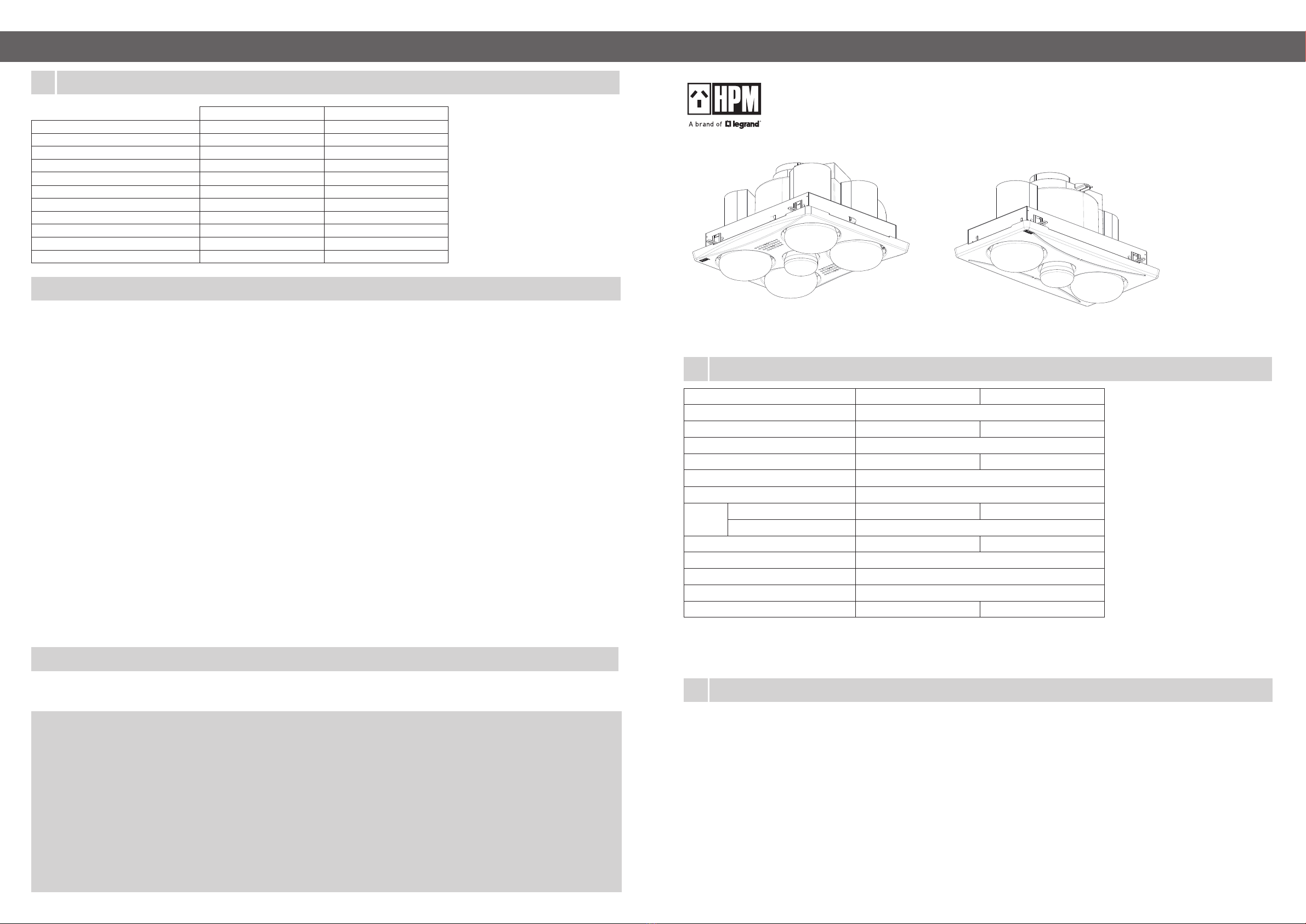
Ducted Instant Heat 3-in-1
2 Heat Lamp model: BH2DWE
4 Heat Lamp model: BH4DWE
Instruction Sheet
1
2
The Ducted Instant Heat 3-in-1 are ceiling mounted heat lamp appliances combining the functions of heater, extraction fan and luminaire.
Read through these instructions completely before commencing installation. Retain for future use.
This product shall be installed by a licensed electrical contractor or similarly qualified person.
CAUTION:
Regulations concerning the discharge of air must be fulfilled. Local building codes may require venting to the outside. The Instant Heat is
for ceiling mounting only, with the lowest point to be at least 2.2 metres above floor level. It is not intended to be installed in wardrobes or
within 300mm of walls. Please note there is a danger of combustion if placed too close to curtains or other flammable materials. Under no
circumstances must the Instant Heat be covered with insulating material within the ceiling space.
Instant Heat must not be installed where there is a possibility of water splashing on to the lamps. Locate in accordance with the
requirements of the Wiring Rules AS/NZS 3000 relating to damp situations. This means that no part may be located directly above any part
of the bath or shower recess or enclosure. For unenclosed showers refer to the Wiring Rules conditions.
Note: Steam will only be removed if there is sufficient flow of air through the room. Ensure adequate inlet openings in the room are
provided, for example through windows, vents or under the door. Air-flow paths from room inlets to fan should ideally pass over
surfaces where condensation may form.
Product Notes
Trouble shooting
1. This product must be installed and used as per these instructions.
2. A switch disconnection must be incorporated in the fixed wiring in accordance with the wiring rules.
3. This appliance is not intended for use by persons (including children) with reduced physical, sensory or mental capabilities, or lack
of experience and knowledge, unless they have been given supervision or instruction concerning use of the appliance by a person
responsible for their safety. Children should be supervised to ensure that they do not play with the appliance.
4. This appliance is intended for household use and similar purposes. It is not suitable for use in an environment heavily laden with dust.
Under these conditions the life of the fan motor can be significantly reduced.
5. This product contains no serviceable parts and no attempt should be made to repair this product. If the product is faulty it should be
discarded.
6. This product must be cleaned periodically from dust and other contaminants with a damp cloth. Aggressive cleaning agents and
solvents should never be used.
7. Airflows listed in this instruction sheet indicate the product performance. Refer to the BCA (Building Code of Australia), or similar,
for the appropriate airflow required for a particular installation.
8. Ventilation products must have an adequate source of external air to ensure correct performance.
9. This product should not be enclosed in thermal insulation as it may cause the unit to overheat.
10. This product has been designed for domestic or similar uses and is not suitable for a commercial installation.
11. Precautions must be taken to avoid the back-flow of gases into the room from the open flue of gas or other fuel-burning appliances.
12. Extended exposure to UV rays (such as exposure to direct sunlight) may cause discolouration of this product.
13. This product is not suitable for installation in hazardous and/or corrosive areas.
14. This product has been designed to operate in ambient temperatures 5°C to 40°C.
15. The material in this product may vary in colour from batch to batch. Colour matching from one batch to another cannot be guaranteed.
16. This product utilises intellectual property in the form of registered designs, trademarks, and/or patents. Such intellectual property
remains the property of Legrand in all cases.
This Instant Heat is fitted with a thermal cut-out to provide over-temperature protection. If the heat lamps begin to switch ON/OFF
intermittently this may indicate the unit was wired incorrectly, allowing the lamps to operate without the fan running. To rectify please
check your installation.
BH2D
BH4D
Box contents
BH2D BH4D
Housing 1 piece 1 piece
Infrared Heat Lamps (275W) 2 pieces 4 pieces
Light globe (7W LED) 1 piece 1 piece
Instruction Sheet 1 piece 1 piece
Warranty card 1 piece 1 piece
Hole-cutting template 1 piece 1 piece
Ducting (3m x Φ150mm) 1 piece 1 piece
Duct holder 1 piece 1 piece
External grille 1 piece 1 piece
Wall switch plate 1 set 1 set
Duct tape and cable ties 1 set 1 set
5
1
4
Specifications
# - measured with 3 m and Φ150 mm ducting.
Note: Airflow will be reduced with bends in duct, squashing of duct, restrictions on replacement air entering the room to be ventilated,
or pressure differentials between the room and outside air and elevation of the outlet duct and grille with reference to the
bathroom heater.
Model: BH2D BH4D
Supply voltage: 230-240 V a.c. 50 Hz
Max. power rating: 840 W max 1570 W max
Airflow#: 180 m3/hr max
Ceiling cut-out: 205 x 395 mm 295 x 355 mm
Projection into ceiling: 205 mm
Required ceiling depth: 300 mm
Fascia Size 440 x 250 mm 400 x 340 mm
Protrusion (excl. lamps) 23 mm
Heat lamps provided: 2 x 275 W 4 x 275 W
Thermal overload protection: 100° C
Draught stopper: Yes
Centre Light provided: 7W LED R80 E27
Weight (excl packaging): 4.3 kg 5.2 kg


