PSI LINK-SEAL User manual
1
Version-10 I 2018 / Art.-Nr.: 3-050-00920
PSI Products GmbH
Ulrichstrasse 25
72116 Mössingen
Phone : (+49) 7473 3781 0
Fax: (+49) 7473 3781 35
www.psi-products.de
MONTAGEANLEITUNG
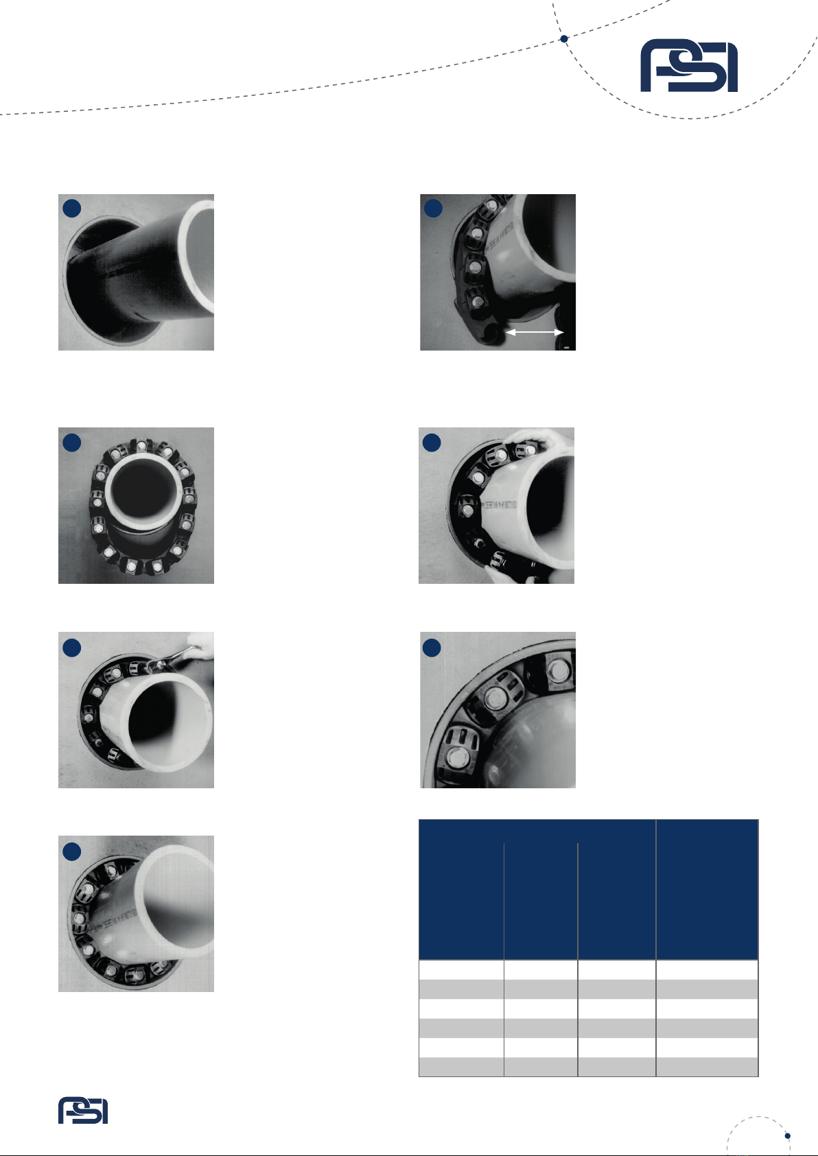
Futterrohr/Kernbohrung und Me-
dienleitung reinigen, Rohr/Kabel
in der Maueröffnung zentrieren.
Medienleitungen müssen geeignet
sein, formstabil und ohne Beschädi-
gungen im Dichtbereich. Kernboh-
rungen müssen maßhaltig und mit
einer glatten Innenwandung ausge-
führt sein. Einbautoleranzen gemäß
Berechnungsprogramm. Das Rohr
benötigt an beiden Enden eine Auf-
lage, die LINK-SEAL®kann nur eine
Abdichtfunktion übernehmen und
dient nicht als Rohrauager oder
Festpunkt. Die Verlegerichtlinien
sind zu beachten.
Alle Schraubköpfe müssen in Rich-
tung des Monteurs zeigen. Ein evtl.
Durchhängen der Kette ist normal.
Entfernen Sie KEINE Segmente. Bei
kleineren Rohren kann es erforder-
lich sein, dass die Kette bei der
Montage gedehnt werden muss!
Beginnen Sie nun auf 12.00 Uhr
Position die Schrauben im Uhrzei-
gersinn anzuziehen. Anziehen nur
mit der Hand, nicht mit Maschinen-
schraubern (Drehmomentschlüssel).
Schraubvorgang nach 2 Std.
wiederholen. Abhängig von den
Einbaubedingungen (Ringraum,
Temperatur, etc.) ggf. mehrfach
nachziehen. Dies gilt im besonde-
ren für die LS 500 bis LS 700.
Empfehlung: Um eine geeignete Dichtäche herzustellen, empfehlen
wir Kernbohrungen mit PSI KB-Epoxidharz zu beschichten. Dies dient
dazu, den Beton zu schützen und eventuelle Lunker/ Riefen zu glätten.
FHRK Standard
LS 200 bis LS 275 FHRK Standard 20, 30, 40
LS 300 bis LS 700 FHRK Standard 20, 30, 40, 60
Einsatz nur in geeigneten Futter-
rohren, Einbautoleranzen gemäß
Maßangaben im Berechnungspro-
gramm. Hier sind die ausgewiese-
nen Spannbereiche zu beachten.
Dies gilt auch für die Abmessungen
der Medienleitungen. Mit geeigne-
ter Dichtäche in der Innenwan-
dung und Steigkeit (Formstabili-
tät nach Einbau) des Futterrohres.
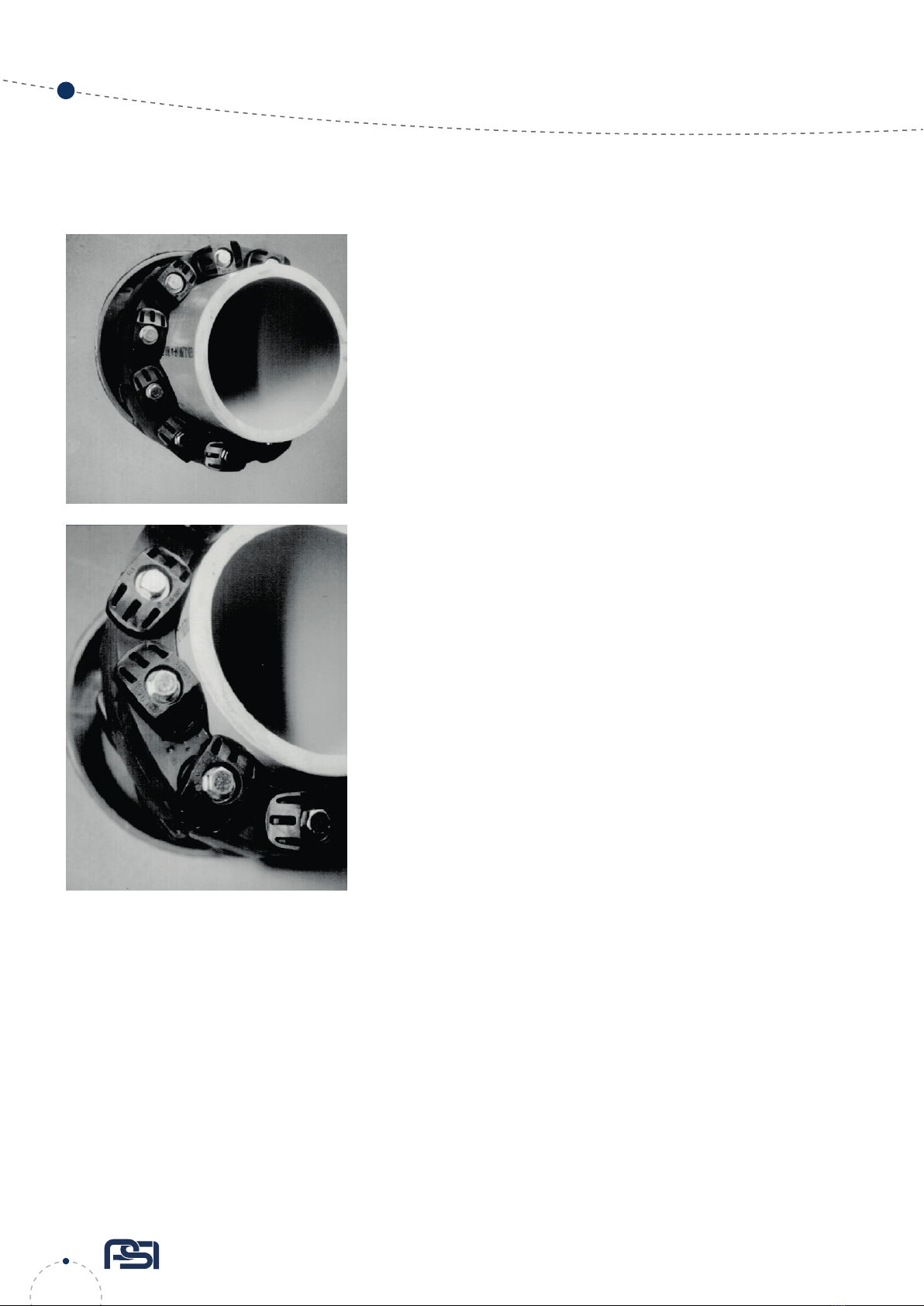
Verbinden Sie die beiden Enden der
Kette. Lösen Sie die hintere Druck-
platte nur soweit, dass sich der
Dichtring frei bewegen lässt.
Schieben Sie den Ring in den Zwi-
schenraum. Die Schraubköpfe
sollen auch nach der Montage zu-
gänglich sein. Bei Ketten mit grö-
ßeren Dichtelementen schieben
Sie zuerst den Ring auf 6.00 Uhr
Position ein und dann auf beiden
Seiten bis zur 12.00 Uhr Position.
Ziehen Sie jede Schraube MAXIMAL 4
Umdrehungen an. Wiederholen Sie
den Vorgang im Uhrzeigersinn unge-
fähr 2 bis 3 mal, bis das Elastomer
gleichmäßig zwischen allen Druck-
platten hervorquillt und der ange-
gebene Drehmoment (s. Tabelle)
erreicht ist.
Max. Anzugsdrehmoment für:
Typ C, S316
Gummi schwarz
O und OS316
Gummi grün
Typ T
Gummi grau
Shore 50°± 5°
Typ BC
und
BS316
Gummi blau,
Shore 40°±5°
Typ LS
Ausführung
KTW/W270
Shore 50°± 5°
Typ
2 Nm 2 Nm 2 Nm LS 200 bis LS 275
8 Nm 6 Nm 8 Nm LS 300 bis LS 360
27 Nm 20 Nm 27 Nm LS 400 bis LS 475
65 Nm 50 Nm 65 Nm LS 500 bis LS 575
110 Nm 65 Nm -LS 615
65 Nm 50 Nm 65 Nm LS 625 bis LS 700
LINK-SEAL®Ringraumdichtung
DE
1
3
5
7
2
4
6
verbinden
Drehmomentschlüssel

2PSI Products GmbH
Ulrichstrasse 25
72116 Mössingen
Telefon: (+49) 7473 3781 0
Fax: (+49) 7473 3781 35
www.psi-products.de
LINK-SEAL®Ringraumdichtung
MONTAGEANLEITUNG
Werkzeuge
Reinigungsmaterial/ Vorbereitung, Messwerkzeug, Drehmomentschlüssel, Hilfsmittel für
Markierungen.
Was ist zu tun?
1. Überprüfen Sie, dass die Dichtglieder, die Rohroberäche und die Kernbohrungs-
bzw. Mauerhülseninnenwandung frei von Schmutz und sonstigen Verunreinigungen sind.
2.Stellen Sie sicher, dass das Rohr zentriert ist.
3. Installieren Sie die Kette und achten Sie darauf, dass die Druckplatten gleichmäßig
ausgerichtet sind.
4. Bauen Sie genau die vorgeschriebene Anzahl von Segmenten ein.
5. Achten Sie darauf, dass das Rohr ordnungsgemäß abgestützt ist, wenn wieder verfüllt wird.
Was Sie nicht tun dürfen!
1. Bauen Sie die Kette nicht ein, solange die Druckplatten nicht ausgerichtet sind.
2. Bauen Sie LINK-SEAL®Ringraumdichtungen nicht auf Spiralrohren ein.
3. Ziehen Sie nicht eine Schraube fest an, bevor Sie zur Nächsten gehen.
4. Nehmen Sie keinen Akku-, Schlag- oder Bohrschrauber.
5. Beachten Sie, dass die LINK-SEAL®keinen Festpunkt darstellt.
Die PSI-Garantie beschränkt sich auf den Ersatz von fehlerhaftem Material.
Die Eignung des Produkts muss vom Anwender für den speziellen
Gebrauch eigenverantwortlich geprüft werden.
Achten Sie auf die richtige Ausrüstung wenn
Sie LINK-SEAL®Ringraumdichtungen installieren
Zertikate unter: www.psi-products.de
DE

3
PSI Products GmbH
Ulrichstrasse 25
72116 Mössingen
Phone : (+49) 7473 3781 0
Fax: (+49) 7473 3781 35
www.psi-products.de
LINK-SEAL®Modular Seals
INSTALLATION INSTRUCTION
EN
Max. torque moment
for Types C,
S316 rubber
black O and
OS316 rubber
green Type
Trubber grey
Shore 50° 5°
for Type BC
and BS316
rubber blue,
Shore 40° 5°
for Type LS
version KTW/
W270 Shore
50° 5°
Type
2 Nm 2 Nm 2 Nm LS 200 up to LS 275
8 Nm 6 Nm 8 Nm LS 300 up to LS 360
27 Nm 20 Nm 27 Nm LS 400 up to LS 475
65 Nm 50 Nm 65 Nm LS 500 up to LS 575
110 Nm 65 Nm -LS 615
65 Nm 50 Nm 65 Nm LS 625 up to LS 700
Recommendation: To create a suitable sealing surface, we recom-
mend coating the core holes with PSI KB epoxy resin. This serves to
protect the concrete and to smooth out any shrinkage holes/scoring.
FHRK Standard
LS 200 to LS 275 FHRK Standard 20, 30, 40
LS 300 to LS 700 FHRK Standard 20, 30, 40, 60
Center the pipe, cable or conduit
in wall opening or casing. Carrier
pipes must be suitable, dimensio-
nally stable and without damage
in the sealing area. Make sure the
pipe is adequately supported on
both ends. The LINK-SEAL®can only
perform a sealing function and does
not serve as a pipe support or xed
point. All building and pipeline gui-
delines are to be observed.
Check to be sure bolt heads are fa-
cingthe installer. Extra slack or sag
is normal. Do not remove links if
extra slack exists.
Note: On smaller diameter pipes,
linksmay need to be stretched.
Start at 12 o’clock. Tighten any bolt
in a clockwise manner. Tighten only
by hand! (torque wrench)
Repeat tightening after approx. 2
hours. Especially for LINK-SEAL®
Type LS 500 up to LS 700 it might
be necessary (depending on the in-
stallation conditions such as annular
space, temperature, etc.) to tigh-
ten again for several times.
Use only in suitable wall sleeves,
installation tolerances according to
dimensions in the calculation pro-
gram. The specied clamping ranges
must be observed here. This also
applies to the dimensions of the car-
rier pipes. With suitable sealing sur-
face in the inner wall and suitable
rigidity (dimensional stability after
installation) of the wall sleeve. Loo-
sen rear pressure plate with nutjust
enough so links move freelytowards
and away from each other connect
both ends of belt.
Slide belt assembly into annular
space. For larger size belts, start
inserting LINK-SEAL®modular seal
assembly at the 6 o’clock posi-
tion and work both sides up to-
ward the 12 o’clock position in the
annular space.
Do not tighten any bolt more than
4 turns at a time. Continue in a
clockwise manner. Make 2 or 3 more
passes at 3 turns per bolt until links
have been uniformly compressed
and the max. torque moment (see
table) is reached.
1
3
5
7
2
4
6
connect
torque wrench
4PSI Products GmbH
Ulrichstrasse 25
72116 Mössingen
Teléphone: (+49) 7473 3781 0
Fax: (+49) 7473 3781 35
www.psi-products.de
LINK-SEAL®Modular Seals
INSTALLATION INSTRUCTION
EN
Tools
Cleaning material/ preperation, meassuring tool, torque wrench, marking aid.
Do‘s
1. Make sure pipe is centered.
2. Install belt with the pressure plates evenly spaced.
3. Install the exact number of links indicated in sizing charts.
4. Check to make sure pipe is supported properly during backll operations.
5. Make sure seal assembly and pipe surfaces are free from dirt.
Dont‘s
1. Don‘t install the belt with the pressure plates aimed in irregular directions (staggered)
2. Don‘t install LINK-SEAL® Modular seals with spiral weld pipe.
3. Don‘t torque each bolt completely before moving on to the next.
4. Do not use high speed power tools.
5. Please note that the LINK-SEAL® isn‘t a xing point.
PSI warrenty is limited to the replacement of faulty material. Theuser himself is responsible to
check if the products he is using aresuitable for his application.
Make sure to have the right equiptment
when installing LINK-SEAL®
Certicates on: www.psi-products.de
Table of contents
Languages:
Popular Industrial Equipment manuals by other brands

Belden
Belden Lumberg LioN-Link 0940 DSL 601 Technical manual

Elite Spas
Elite Spas Platinum I owner's manual

Schmalz
Schmalz Mini Compact Ejector SCPMc operating instructions

Maco
Maco A-TS Assembly instructions

Comelit
Comelit 4791 Mounting instructions

Siemens
Siemens SIMATIC HMI Industrial Thin Client ITC1200 operating instructions


KNECHT
KNECHT S 200 S operating instructions

Sewosy
Sewosy CPREG-1 Mounting instructions

Sentry
Sentry Saf-T-Vise STV-HP3 Installation, operation & maintenance manual

ABB
ABB HT562960 Operation manual

Siemens
Siemens SIMATIC 6DL2804-3 Series Hardware installation manual

Schmalz
Schmalz SCPMc operating instructions