PSS TSC 1500XL User manual

TSC
Model: 1500XL
Installation Instructions
Please read all instructions before attempting installation or operation of these units
SAVE THESE INSTRUCTIONS FOR FUTURE USE
PUBLICATION NO.
8 5 1 7 5 1 2 3 0 R e v A
A p r i l 5 , 2021

TSC 1500XL
1
Contents
Section Page No.
Introduction 2
Cautions and Warnings 3
Installation 5

TSC 1500XL
2
Introduction
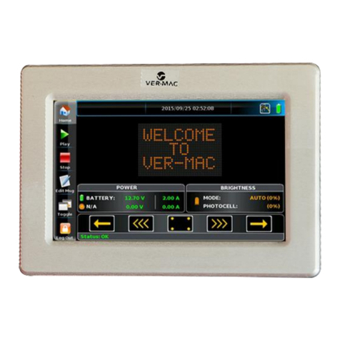
The TSC 1500XL system is comprised of multiple components, a Master Node that
provides the interface for the operator and a Touchscreen that provides the control for the
devices.
The TSC 1500XL is equipped from the factory with a default password for the administrator and
the operator. The system administrator can easily reprogram each of the passwords to fit their
individual security requirements. Further, the administrator can change the passwords as
frequently as necessary.
TSC 1500XL was designed with the capability to control each device independently or control
multiple devices for predetermined court setups. The predetermined programs can be edited, as
necessary.
The TSC 1500XL is also equipped with a Manual Control Override and can be used for
troubleshooting by hooking it directly into the relay board inside the Node panels.

TSC 1500XL
3

TSC 1500XL
4
INSTALLATION INSTRUCTIONS
Tools Required:
Drill
0# Phillips screwdriver
1/8” Blade screwdriver
2mm Blade screwdriver
Ratchet with sockets
Wire Required:
Communication cable between Node panels: Serial Data cable equivalent to Carol C0842A or
Belden 9842 (120-ohm impedance). CAT Ethernet cable cannot be used. No Substitutions.
Communication cable for Touchscreen: Cat 6 (Size based on job) No Substitutions.
Installation Procedure
System consists of a Master Node panel and one or more Secondary Node panels, dependent on
the size of the job, and one touchscreen supplied by Performance Sports Systems.
Determine location for Master Node, all nodes should be securely mounted in a location
that is easily accessible for maintenance and operation of the Manual Control Override.
Once the relay box has been properly mounted, wiring of the system can be accomplished.
Refer to System Wiring Configuration drawing (Page 5) from Performance Sports
Systems, Model TSC 1500XL.

TSC 1500XL
5
- Connection of power to the Master and Secondary Nodes are as follows:
Electrical Service Requirements - 120V, 15A, 1PH service
Power can be run directly to the Node panel. Feed line should be sized appropriately for
the length of run to meet the electrical service requirements.
1. Connect the power wires to the Node panel as follows (see Figure 1).
➢Incoming hot to Black terminal block on the left side of the power supply.
➢Incoming neutral to be landed on terminal 40.
➢Ground to be landed on terminal 8.
Figure 1
Note: All AC wiring should be routed away from DC Communication and Control wiring and
should never intersect or cross.

TSC 1500XL
6
- Connect power for the devices
1. A separate power line for each device is recommended.
2. Wire neutrals together at another location per local electrical codes.
3. Bring the hot wire into the Node panel and land at the IN location at the terminal. (See
figure 2)
Figure 2
- Connect device motors to Relay Board as follows:
Requires a 4-wire line sized appropriately for the length of run (minimum recommended
size as follows):
•12 AWG for up to 90 feet of run
•10 AWG for 90 feet to 140 feet of run
•8 AWG for 140 feet to 240 feet of run
•6 AWG for 240 feet to 380 feet of run
1. Connect the motor wires from the devices to the Relay Board as noted in the design form.
Land all other devices as noted in the design form.
a. Terminal blocks on relay board only accept 10 AWG wires. If wire coming into
box is too large it must be stepped down in size to connect.
b. Device wires will land on the UP and Down locations at each terminal blocks.

TSC 1500XL
7
–Connect Communication and Power for Touch Screen
1. From the Master Node to the Touch Screen run Cat 6 and three 14ga or 12ga wires, in its
own conduit free from high voltage lines.
2. Connect the Cat 6 cable at the Master Node panel and at the Touchscreen. This uses a
standard RJ-45 connection on both ends. The Master Node connection will connect on
an open spot on the Ethernet Switch. (See figure 3) The Touch Screen connection will
connect to the Ethernet port labeled “Ethernet”.
.
Figure 3
3. At the Master Node panel, run a line from terminals 6,7, & 8 to the Touch Screen. At the
Touchscreen land, the wire from terminal 6 on the Positive (+) terminal, then land the
wire from terminal 7 on the negative terminal (-) and lastly land the wire from terminal 8
to (FG) terminal. (See figure 4)
Figure 4

TSC 1500XL
8
- Connecting the Master Node to Secondary Node panels.
•Serial Data cable equivalent to Carol C0842A or Belden 9842 (120-ohm impedance).
CAT Ethernet cable cannot be used. No Substitutions.
•Requires RJ-45 connector (Included per Node panel).
- Master Node connections.
Figure 5
NOTE: Strip Serial Data cable no more than 2”from the end. Clip off any unused wires. Route
Serial Data cable away from any high voltage lines when connecting to secondary node panels.
1. Connect the Serial Data cable to the Master PLC as shown in Figure 5. Use the chart for
correct wire assignments.
2. Make sure Serial Data cable shielding is landed on the shield terminal at the PLC.
3. When connecting to Secondary Nodes, use the supplied RG-45 connector.
4. See page 9 for Pin assignments for the supplied RJ-45 connector.
TSC Cable Termination
Example.
Signal Name
Master PLC
NC
No Connection
CAN.H
OR/WH
Shield
BARE SH
CAN.L
OR
GND
GR/ WH

TSC 1500XL
9
-Cable connection at Secondary Node panels.
Figure 6 Figure 7
Note: Follow installation below for connecting the RJ-45 connector to Serial Data cable (this
guide is also included with RJ-45 connector). Ethernet cable is shown as an example.

TSC 1500XL
10
-Cable connection at Secondary Node panels (cont.).
•Incoming Serial Data cable will plug into the CN1 port on the Secondary Node panel.
•The CN2 port is reserved for out going signal to additional node panels or the
Termination Resistor for the last node panel.
Figure 8
Termination Resistor
NOTE: For safe and reliable communication between the system components it is imperative
that the interconnected wiring be installed correctly and according to these instructions.
Failure to do this can result in an inoperative system, sluggish response, or inability to
reliably control the system components.
NOTE: Do not run communications cable through conduits or junction boxes with any other
wires except the low voltage wires between TSC system components. Do not run low
voltage wires through conduits or junction boxes containing any of the 120v motor wires
from the field devices such as backstops or curtains.
NOTE: Make note of wire color attached to each terminal. This may vary depending on brand
of twisted pair shielded cable in use.
Incoming Serial Data
line. CN1
Termination Resistor.
CN2

TSC 1500XL
11
-Proper Grounding and Shielding
Proper grounding and shielding are essential for reliable system operation. Low voltage DC and
communication wiring must be protected from electrical noise introduced by 120v AC wiring,
other voltages and signals which may be present in the building infrastructure.
1. The main 120v power feeds from the breaker panel to the RB should have a separately
pulled Green ground wire. This should be bonded to the breaker panel source.
Note: Supplied voltage must be constant. If not, constant errors can occur.
Plug all open holes.
1) After installation of conduit and wire, all open holes must be plugged by electrician.
Wiring Practices:
All AC wiring should be routed away from DC, Communication, and Control wiring and
should never intersect or cross. Failure to do so can cause communication issues with an
installed system.
Ideally locate the Master and Secondary Nodes somewhere easily accessible such as in an
electronics room or catwalk. The reason for this is access to the Manual Control Override
feature and for any service needs.
Do not install the box on the ceiling. It is not designed to be installed in this manner
and doing so will cause operation problems.
Contact Performance Sports Systems at 800-848-8034 extension 236 for questions or
additional information concerning the TSC 1500-WiFi installation

Performance Sports Systems
9200 E. 146th Street
Noblesville, IN 46060
800-848-8034
www.perfsports.com
Table of contents
