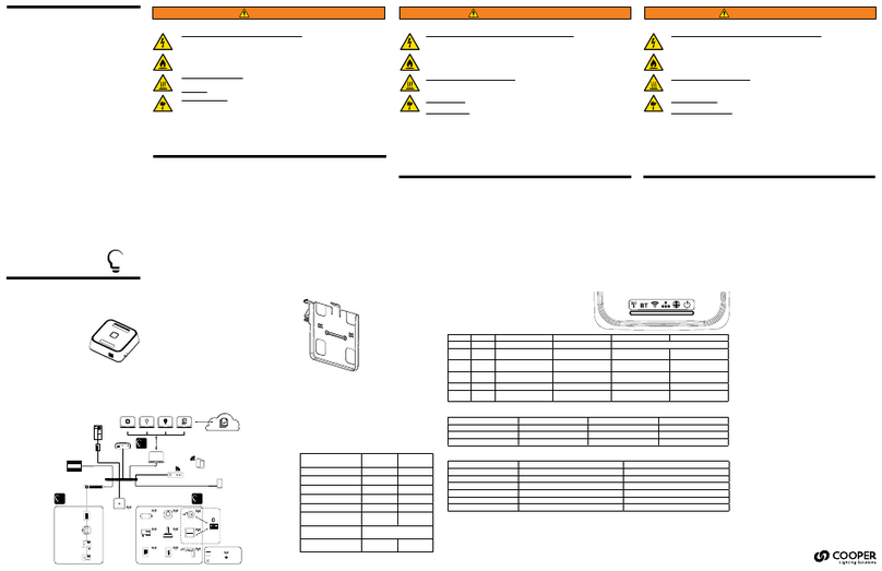
Mounting & Installation Technical Data
Typical Schematic
Electrical Data
Supply: 120 - 277VAC -/+ 10%, 50/60 Hz, 0.2A Max
Terminals max. wire size: 2.5mm2
Switch inputs: 2, congurable as break or make, max wire size 2.5mm2
iCANnet™ inputs/output: Screw terminals
iCANnet™ output current: 300mA Max @ nominal 15V
DALI output screw terminals: Max wire size 2.5mm2
DALI signal: Nominal 16V, max current 250mA supplies to each universe.
Guaranteed minimum current: 245mA.
Short circuit protection in accordance with section 6.6.2 of IEC FDIS 62386-101.
DMX signal: Addressable in Device Editor, DMX512-A
Terminals max wire size: 1 x 2.5mm2or 2 x 1.5mm2per circuit
Protection: Provided by installer
Mechanical Data
Dimensions: 159mm (w) x 89mm (h) x 60mm (d) (6.26” x 3.5” x 2.36”)
Housing: DIN rail case; 9 module width
Weight: 0.35kg (0.77lb)
IP rating: IP20
Operating Conditions
Operating temperature: +2°C to 50°C
Relative humidity: 5% to 95% non-condensing
Max Storage Temperature: +60°C
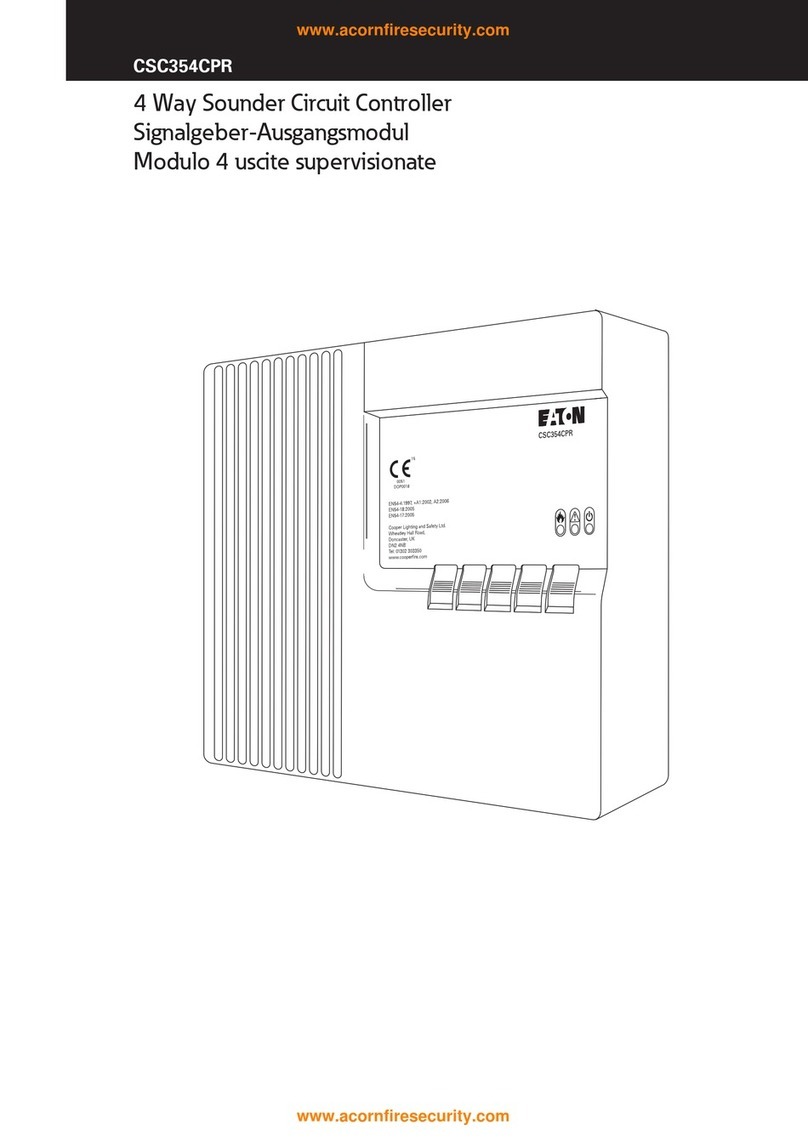
SCMD4
4 Universe Addressable DALI-2
Controller
Installation Guide
Cooper Lighting Solutions
UK
Usk House, Lakeside, Llantarnam Park,
Cwmbran, NP44 3HD, UK
t: +44 (0)1923 495495
www.
cooperlighting.co.uk
US
1121 Highway 74 South
Peachtree City, GA 30269
www.cooperlighting.com
P: 1-800-553-3879
Canada
5925 McLaughlin Road
Mississauga, Ontario L5R 1B8
P: 905-501-3000
F: 905-501-3172
Doc No: 9850-000767-01
E&OE. Cooper Lighting Solutions
reserve the right to make changes to
the equipment without prior notice.
© Cooper Lighting Solutions
iCANnet
DALI Line
SCMD4
DALI
Control Panel
DALI
Sensor
SCMD4
FM 664349
SCMD4 must be mounted in a suitable enclosure to provide regulatory
protection from electric shock hazard as well as protecting the iCANnet
data network from tampering that could lead to reduced network security.
Ensure selected enclosure provides adequate cooling ventilation.
Fixing to DIN rail
1. Fix top clips over DIN rail.
2. Pull down bottom clip using screwdriver.
3. Close module towards DIN rail.
4. Push up bottom clip to x securely to DIN rail.
Removing from DIN rail
1. Pull down bottom clip with screwdriver.
2. Lift module away from DIN rail.
1
2
3
4
1
2
