Lindsay Broadband LBVM900 Series User manual
LBVM900 Series 1 GHz Indoor High Output Optical Node
Installation & Operation Manual
Page 1 of 4
The LBVM900 high output optical node is designed for various applications from HFC to advanced fiber deep FTTH architecture networks. The LBVM900 node
features a 1000 MHz bandwidth, high RF output level up to 50 dBmV (110 dBμV) and a wide selection of return lasers including CWDM wavelengths as an option to
overcome fiber limitations in a network for two-way services. All of these features and flexibility are packaged in a compact, diecast aluminum housing.
FEATURES
•1002 MHz high output with GaAs technology
•Optional WDM technology available for bi-directional services on a single fiber
•Superior heat dissipation
•I/O optical level test points
•High RF output 50 dBmV (110 dBμV)
•Compact, diecast aluminum housing
•Low power consumption
•-20 dB directional coupler test points for forward & reverse RF
PRODUCT OVERVIEW
•Model: LBVM900
•Bandwidth: 5-42 MHz/54-1002 MHz; 5-65 MHz/85-1002 MHz; 5-85 MHz/102-1002 MHz
•Powering: 12-30 VDC
CAUTION
Risk of electric shock. Do not open.
No serviceable parts inside. Refer servicing to qualified service personnel.
Invisible laser radiation! Avoid eye injury. Never look into the optical cable or connector.
SPECIFICATIONS
Parameter Specification
Forward Receiver
Optical Receive Wavelength 1200-1600 nm
Monitor Voltage 1 V/mW
Optical Input -6 to +2 dBm
Optical Input Return Loss (Min.) 45 dB
RF Frequency Range
(1)
54-1002 MHz
Flatness of Frequency Response (f = fmin-1218 MHz) ± 0.75 dB
Output Return Loss (f = fmin-1218 MHz) 16 dB
Reference Output Level (± 2 dB @ -1 dBm optical input) 36-50 dBmV
Slope (± 1 dB) 14 dB
C/N
(2)
50 dB
CTB
(2)
-64 dB
CSO
(2)
-60 dB
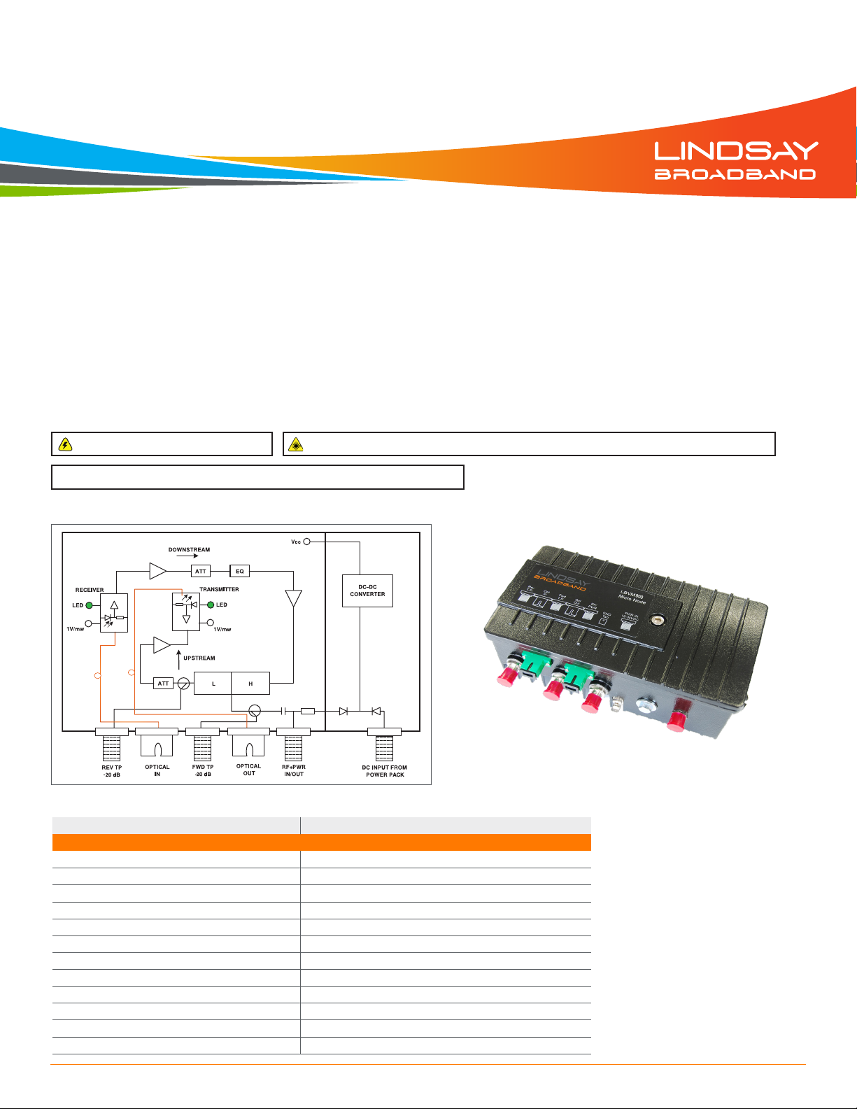
FUNCTIONAL SCHEMATIC
LBVM900
(front angled view)

LBVM900 Series 1 GHz Indoor High Output Optical Node Installation & Operation Manual
Page 2 of 4
OPTICAL, RF & POWER CONNECTIONS
1. The powering port and all RF ports are standard F-type coaxial connectors. The optical connector(s) are a SC/APC female-type.
2. The LBVM900 can be powered by applying 12-30 VDC via F connector labeled "PWR IN". 100-240 VAC to 29 VDC switching power pack is supplied in the box.
3. Connect a coaxial cable from the output of the power pack to the PWR IN port on the LBVM900.
4. The LBVM900 can also be powered from the RF OUT/PWR IN port by combining RF and power via a power inserter.
5. After connecting the coaxial cable between the power pack output and the LBVM900, plug the power pack into the wall receptacle.
6. The LBVM900 adjustment plug-ins, status indicator LEDs and DC test points (TPs) are located under the lid of the ONU. The lid can be opened using a size #5
Allen key.
7. When the LBVM900 powers up, the DC POWER ON LED will illuminate. As the LBVM900 is an HFC node with upstream transmitter always ON, the LASER ON
LED will also illuminate as soon as the LBVM900 powers up.
8. Connect the LBVM900 chassis to physical earth (ground) by using the grounding screw on the LBVM900.
9. The LBVM900 receiver is a wide range receiver that accepts all downstream wavelengths from 1200-1600 nm. However, if the LBVM900 is a single fiber (WDM)
unit then the receiver range is limited to 1550 ± 10 nm. Please note that a single fiber WDM LBVM900 cannot have the same receiver and transmitter wavelength,
while a dual fiber LBVM900 could operate on the same receive and transmit wavelength since the transmitter & receiver wavelength travel on different fibers.
10. The LBVM900 accepts optical levels from -6 dBm to +2 dBm. Using an optical power meter at appropriate downstream wavelength, make sure the optical level on
the incoming fiber is within range.
11. Make sure the optical cable is matched for the proper connector (ie. SC/APC to SC/APC). After cleaning all optical connectors, connect the optical fiber(s) to the
OPT IN/OUT port on the ONU.
12. If the input optical power is within range, the OPT ON LED on the photo diode will illuminate. Once the optical fiber is connected to the ONU, the O.P. TP 1 mW/1
VDC test point (TP) on the photo diode can be used to measure the optical input detected by the forward receiver in the ONU. Use a digital multimeter on DC
voltage setting and measure between the DC TP and the grounding screw. See table below for relation between measured DC voltage on O.P. TP and optical
power on the LBVM900 optical node.
SPECIFICATIONS CONT'D.
Parameter Specification
Return Transmitter
Optical Wavelength (CWDM available) 1310, 1550, or 1610 nm
Optical Output Power (DFB laser) 2 or 3 mW
Optical Output Return Loss 45 dB
RF Input Level (Total power)
(3)
10-25 dBmV
RF Input Frequency Range
(1)
5-42 MHz
Flatness of Frequency Response (f = 5-fmax MHz) ± 0.75 dB
Input Return Loss (f = 5-fmax MHz) 16 dB
Power, Environmental & Physical
Total Power Consumption (30 VDC power pack) < 14 W
Operating Humidity 5-95%, non-condensing
Operating Temperature -40°C to +60°C (-40°F to +140°F)
Dimensions (H x W x D) 4.7”H x 8.3”W x 3.1”D (12.0H x 21.0W x 8.0D cm)
Weight 2.2 lb (1.0 kg)
NOTES:
(1) Other diplex splits available; 65/85 MHz, 85/102 MHz
(2) -1 dBm optical input; 3.5% OMI/CH; channel loading 54-550 MHz analog channels & digital compressed or equivalent
broadband noise above 550-1002 MHz at levels 6 dB below equivalent video
(3) NPR @ 38 dB. Measured using a receiver with an equivalent input noise (EIN) of < 2.5 pA/Hz0.5 with a link budget of 6 dB
(10 km fiber + passive loss)
V (DC) on 1 mW/1V O.P. TP
DC Test Point of ONU Optical Level (mW) Optical Level (dBm) OPT ON LED Notes
2.00 2.00 3 ON Blinking Too high input
1.58 1.58 2
ON
No optical AGC
1.26 1.26 1
1.00 1.00 0
0.79 0.79 -1
0.63 0.63 -2
0.50 0.50 -3
0.40 0.40 -4
0.32 0.32 -5
0.25 0.25 -6
0.20 0.20 -7
0.16 0.16 -8
OFF
0.13 0.13 -9
0.10 0.10 -10
< -10 Out of limit
LBVM900 Series 1 GHz Indoor High Output Optical Node Installation & Operation Manual
Page 3 of 4
OPTICAL, RF & POWER CONNECTIONS CONT'D.
FORWARD & REVERSE SETUP GUIDELINES
1. Please note that LBVM900 uses JXP attenuator pads for output/input level control (forward/reverse pad) and 1 GHz JXP type equalizer for forward
equalizer plug-in.
2. For the forward path setup, make sure that the forward optical input level to the LBVM900 is within range as shown in the table in section OPTICAL, RF & POWER
CONNECTIONS above. If the optical input is higher than +2 dBm, receiver overload may occur. If the optical input is < -6 dBm, the LBVM900 will deliver very
low RF output. The LBVM900 does not have AGC (Automatic Gain Control), and the RF output depends on the optical input to the ONU. The LBVM900 delivers
optimum performance at -1 dBm optical input level.
3. The specified RF output level of 50 dBmV at 1 GHz is only guaranteed at -1 dBm optical input and with OMI ≥ 3.5% on the downstream optical signal. The output
will drop a further 2 dB with every 1 dB drop in optical input.
4. To compensate for RF cable losses, the forward equalizer plug-in comes with a 15 dB JXP equalizer installed from the factory. This results in a 15 ± 1 dB slope on
the RF output of LBVM900 from low frequency to high frequency. The forward slope (tilt) can be changed by changing the forward equalizer plug-in value. Use only
1 GHz JXP equalizers in the forward equalizer plug-in.
5. Connect a signal level meter at the RF OUT port to measure the RF output from the LBVM900. You can also use the forward output -20 dB TP to measure the RF
output.
6. If the output level is too high or low, the forward pad plug-in can be changed to adjust the output of LBVM900. The forward pad plug-in takes a JXP attenuator pad.
7. Verify the RF output levels from the LBVM900 are as expected.
8. This completes the forward path setup for the LBVM900 ONU.
9. The LBVM900 is also available in a downstream only model. If using a receive only LBVM900 node, then ignore the reverse (upstream) path setup.
10. For the reverse path setup, make sure that the reverse input level to the LBVM900 is not too high or damage to the ONU may occur. The -20 dB forward TP is a
bi-directional TP and can also be used to inject the upstream test carrier. Compensate 20 dB if using the forward TP to inject the upstream test carrier. The injected
upstream test carrier can be measured on the -20 dB reverse input TP of the LBVM900.
11. The upstream transmitter in the LBVM900 is a continuous ON laser transmitter and is always active. The LASER ON LED on the laser diode indicates the status of
the laser transmitter and will be illuminated when the LBVM900 turns ON (irrespective of upstream RF input).
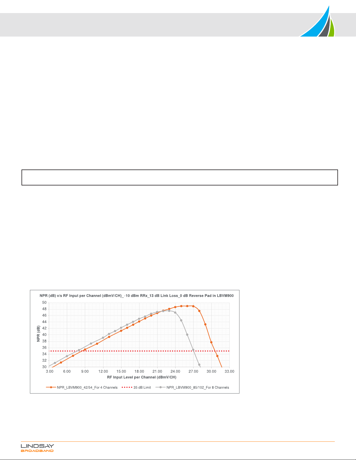
12. Make sure the upstream RF input is within the upstream frequency and input level range. The upstream RF input range for LBVM900 is 10-30 dBmV per channel
(digital channel level) for 42/54 MHz LBVM900 and 10-27 dBmV per channel (digital channel level) for 85/102 MHz LBVM900. These upstream levels are assumed
with the condition that a 42/54 MHz split unit will have 4 equally loaded channels in the upstream band, and the 85/102 MHz split will have 8 equally loaded
channels in the upstream band. If using a different number of channels from what is mentioned above, compensate for total RF power. The total RF input level to the
LBVM900 (for all channels combined) should not exceed more than 36 dBmV (digital channel level). More than 36 dBmV (digital channel level) total upstream RF
input may cause laser clipping and saturation on the LBVM900. Use the following formula to calculate total RF power: Total RF power = RF power per channel +
[10* log (# of channels)].
13. Refer to the NPR plot below to better understand the RF input levels to the LBVM900.
14. For optimum performance in the upstream direction, make sure the LBVM900 is operated with RF input levels to the left side of the NPR peak. Operating at RF
input levels to the left side of the NPR peak will provide the best MER/BER performance while assuring the laser saturation and clipping does not occur on the laser
transmitter.
15. This completes the reverse path setup for the LBVM900 ONU.
16. If you have any more questions regarding the LBVM900 setup, please contact Lindsay Broadband for support.
NOTE: The RF levels mentioned in this manual are analog channel levels, unless specified. For digital channels assume 6 dB less to that of
analog channels.
13. The F-port labeled "RF" is the bi-directional RF input and output port for the LBVM900 optical node.
14. There are separate forward output and reverse input -20 dB TPs labeled “FWD TP” and “REV TP” respectively. When not in use, please terminate these -20 dB
TPs with a 75 ohm terminator.
15. When using the -20 dB TP to measure the RF input/output levels, make sure the RF port is terminated to 75 ohm. Please note the levels from -20 dB TP will be 20
dB lower than the RF port.
LBVM900 Series 1 GHz Indoor High Output Optical Node Installation & Operation Manual
2-2035 Fisher Dr, Peterborough, ON K9J 6X6 Canada
+1.705.742.1350 • 1.800.465.7046 • support@lindsaybb.com • lindsaybb.com
© 2021 Lindsay Broadband Inc. All rights reserved. Printed in Canada. Non-Lindsay Broadband product marks,
service marks, and company names in this document are the property of their respective owners. All information is subject to change without notice.
Rev. 07/21 (LBB0376) • Page 4 of 4
TROUBLESHOOTING GUIDELINES
1. No Power on the LBVM900 ONU.
a. Check the powering coaxial cable and connections for intermittent connections.
b. Check the output of the power adaptor for proper DC voltage (+29 VDC).
c. Check with a different 29 VDC power pack.
d. Try powering via the RF OUT/PWR IN port using a power inserter.
2. Low or no downstream RF output level.
a. Verify the optical receive level on the LBVM900 is within range (-6 dBm to +2 dBm, 3.5% OMI level and correct downstream wavelength).
b. Using a fiber inspection scope, check the optical connector and adaptor. Make sure the optical connection is clean.
c. If the optical input is within range, the OPT ON LED on the photo diode is illuminated. Verify that the OPT ON LED is illuminated. Use a DC voltage meter to
measure the 1 mW/1V OP TP on the photo diode of the ONU. Refer to step #13 and table under the OPTICAL, RF & POWER CONNECTIONS section of
this manual.
d. Verify steps 2 to 8 under the FORWARD & REVERSE SETUP GUIDELINES of this manual for more troubleshooting.
e. Check for intermittent connections or pinched fibers.
3. Low or no upstream transmit level.
a. Verify the LASER ON LED on the LBVM900 ONU is illuminated. Measure the OP TP 1V/1 mW DC TP on the laser diode using a digital multimeter on DC
voltage setting. Verify the DC voltage reading is as expected from table under the OPTICAL, RF & POWER CONNECTIONS section of this manual.
b. Connect an optical power meter to the OPT OUT port. Using the optical power meter at proper upstream wavelength, verify the optical output of the
LBVM900 directly from OPT OUT port is ≥ 2.7 dBm.
c. Verify the upstream RF input is within the LBVM900 upstream frequency range (5-42 MHz or 5-85 MHz) and level. Refer to reverse setup guidelines.
d. Use a CW carrier for injection to troubleshoot.
e. Inject either from the RF OUT port or using the bi-directional -20 dB forward TP. Make sure to compensate 20 dB if using the -20 dB TP to inject carrier.
f. The RF input can also be verified at the reverse -20 dB TP.
g. Check for intermittent connections.
4. If the problem is still not solved, replace, and try with another node.
5. If the problem still exists, contact Lindsay Broadband for support. Do not open the LBVM900 as it will void the warranty.
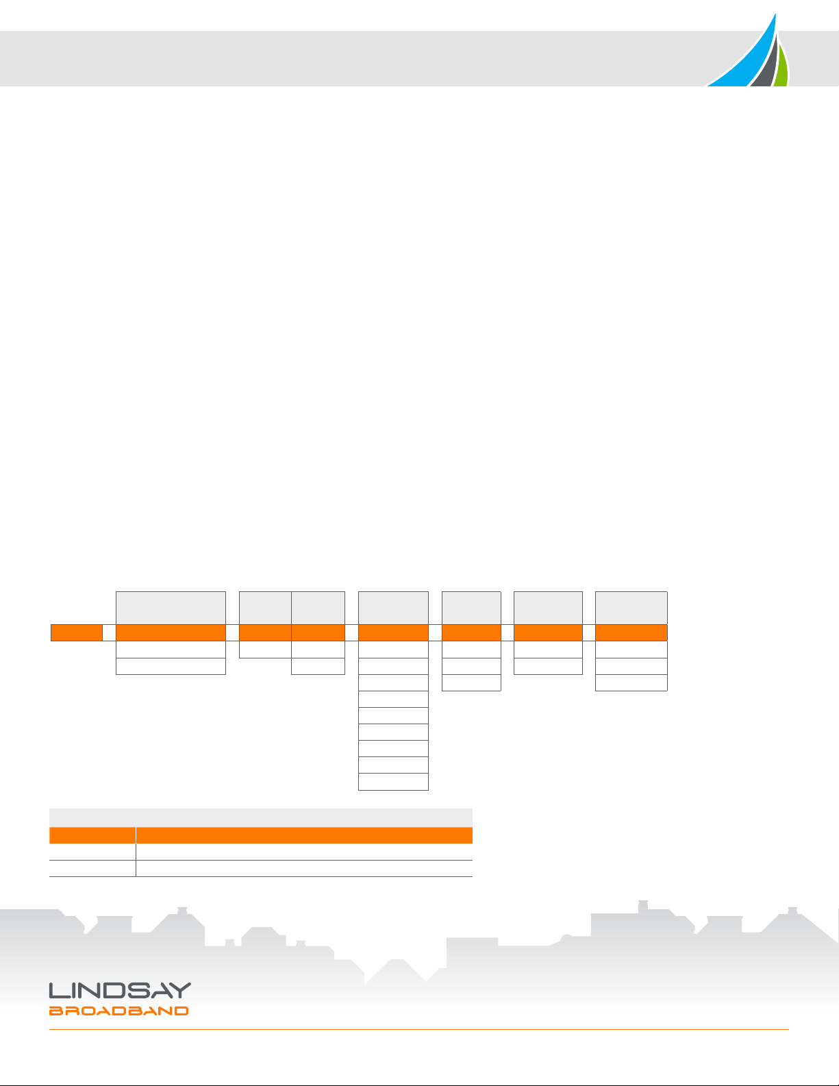
ORDERING INFORMATION
# of Fibers Laser TX TX Sub-Split Optical Power
Type Power Wavelength Connector Adaptor
LBVM900 −x−D x −xx −xx −xx −x
S = Single (WDM) D = DFB 2 = 2 mW 31 = 1310 nm 45 = 42/54 SA = SC/APC 0 = None
D = Dual (RX & TX fibers) 3 = 3 mW 47 = 1470 nm 68 = 65/85 SU = SC/UPC 1 = N. America
49 = 1490 nm 81 = 85/102 2 = Europe
51 = 1510 nm
53 = 1530 nm
55 = 1550 nm
57 = 1570 nm
59 = 1590 nm
61 = 1610 nm
COMPLETING THE INSTALLATION
1. Record the input and output levels for the station in both upstream and downstream for reference.
2. Make sure the cables are routed properly and all connections are secured.
3. Ensure the optical fiber cable is not pinched and does not have sharp bends.
Optional Accessories
Part # Description
LBVM900GP-xdB Plug-in attenuator (x = dB value; available values = 0, 2, 4, 6, 8, 10, 12, 14, 16)
LBVM900GE-xdB Plug-in equalizer (x = dB value; available values = 3, 6, 9, 12, 15, 18)
Other Lindsay Broadband Power Supply manuals


Popular Power Supply manuals by other brands

Videx
Videx 520MR Installation instruction

Poppstar
Poppstar 1008821 Instructions for use

TDK-Lambda
TDK-Lambda LZS-A1000-3 Installation, operation and maintenance manual

TDK-Lambda
TDK-Lambda 500A instruction manual

Calira
Calira EVS 17/07-DS/IU operating instructions

Monacor
Monacor PS-12CCD instruction manual


