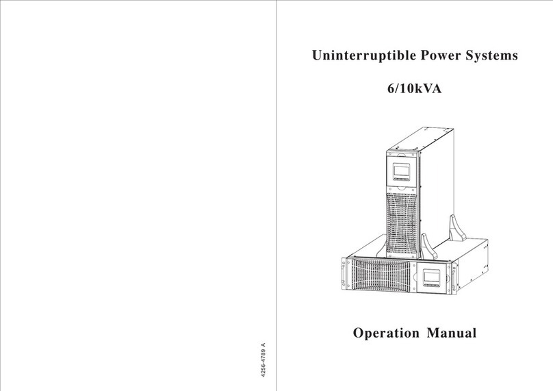
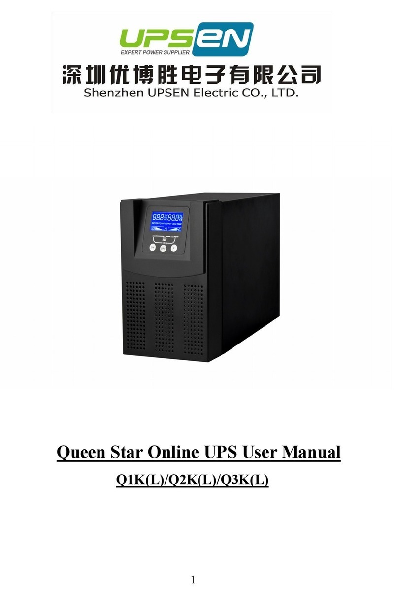
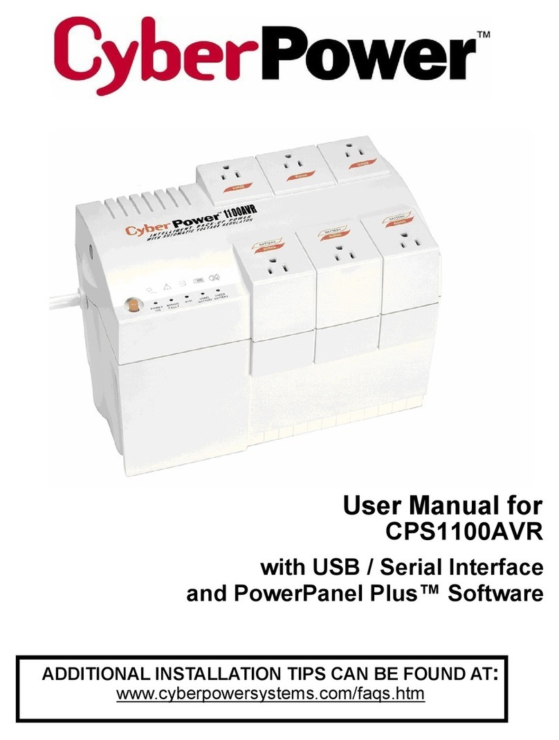
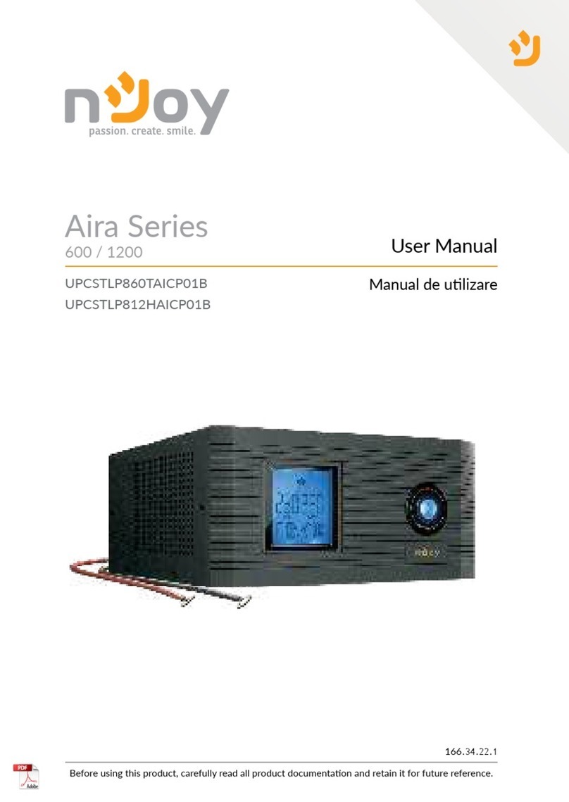
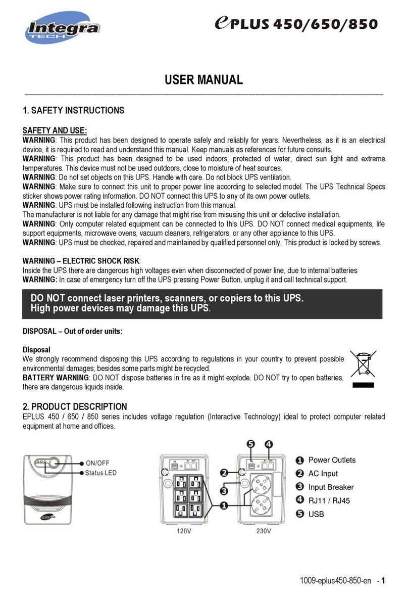
PSS 1K User manual

4256-xxxx

1
1KVAto3KVARack-TowerconversionUser’s
Guide

2
Class B EMC Statements
(High Voltage Models up to 3000 VA)
FCCPart15
NOTEThisequipmenthasbeentestedandfoundtocomplywiththelimitsforaClassBdigitaldevice,
pursuanttopart15oftheFCCRules.Theselimitsaredesignedtoprovidereasonableprotection
againstharmfulinterferenceinaresidentialinstallation.Thisequipmentgenerates,usesandcan
radiateradiofrequencyenergyand,ifnotinstalledandusedinaccordancewiththeinstructions,may
causeharmfulinterferencetoradiocommunications.However,thereisnoguaranteethat
interferencewillnotoccurinaparticularinstallation.Ifthisequipmentdoescauseharmful
interferencetoradioortelevisionreception,whichcanbedeterminedbyturningtheequipmentoff
andon,theuserisencouragedtotrytocorrecttheinterferencebyoneormoreofthefollowing
measures:
●Reorientorrelocatethereceivingantenna.
●Increasetheseparationbetweentheequipmentandthereceiver.
●Connecttheequipmentintoanoutletonacircuitdifferentfromthattowhichthereceiveris
connected.
●Consultthedealeroranexperiencedradio/TVtechnicianforhelp.

3
SpecialSymbols
ThefollowingareexamplesofsymbolsusedontheUPSoraccessoriestoalertyoutoimportant
information:
RISK OF ELECTRIC SHOCK - Observe the warning associated with the risk of electric shock
symbol.
CAUTION,need your attention
This symbol indicates that you should not discard the UPS or the UPS batteries in the trash. This
product contains sealed, lead‐acid batteries and must be disposed of properly. For more information,
contact your local recycling/reuse or hazardous waste center.
This symbol indicates that you should not discard waste electrical or electronic equipment (WEEE) in
the trash. For proper disposal, contact your local recycling/reuse or hazardous waste center.

4
Table of Contents
1Introduction……………………………………………………………………………………………………5
2SafetyWarnings………………………………………………………………………………………………6
3Installation………………………………………………………………………………………………………7
4Operation………………………………………………………………………………………………………19
5Communication……………………………………………………………………………………………………………..35
6UPSMaintenance…………………………………………………………………………………………..40
7Specifications…………………………………………………………………………………………………44
8Troubleshooting……………………………………………………………………………………………………………49

5
1Introduction
ThisUPSprotectsyoursensitiveelectronicequipmentfrommostcommonpowerproblems,including
powerfailures,powersags,powersurges,brownouts,linenoise,highvoltagespikes,frequency
variations,switchingtransients,andharmonicdistortion.
Poweroutagesmightoccurunexpectedlyandpowerqualitycanbeerratic.Thesepowerproblems
havepotentialtocorruptcriticaldata,destroyunsavedworksessions,anddamagehardware—
causinghoursoflostproductivityandexpensiverepairs.
WiththeUPS,youcansafelyeliminatetheeffectsofpower
disturbancesandguardtheintegrityofyourequipment.Providing
outstandingperformanceandreliability,theUPS'suniquebenefitsinclude:
zTrueonlinedouble-conversiontechnologywithhighpowerdensity,utilityfrequency
independence,andgeneratorcompatibility.Outputpowerfactorupto0.9.
zThreesegmentchargingmodetoincreasebatteryservicelife,optimizerechargetime.
zSelectableHighEfficiencymodeofoperation.
zColdstartfunctiontostartuptheUPSwithoututility.
zStandardcommunicationoptions:oneRS-232communicationport,oneUSBcommunication
port,andrelayoutputcontactsorSNMPcard.
zPowerSheddingfunctionmayturnoffuncriticalloadinbatterybackuptomakelongerbackup
timeforcriticalload.
zExtendedruntimewithuptofourExtendedBatteryModules(EBPs)perUPS.
zEmergencyshutdowncontrolthroughtheRemoteEmergencyPower-off(EPO)port.
zThecontentdisplayedontheinterfaceisrich.Thecapacityoftheloadsandthebatterycanbe
seendirectlyandtheFLASHpicturesandfanrotatingiconcanbedisplayedwhilecharging.
Enhance,itiseasytoknowitsoperationstatus.WhenUPSfails,itcanshowthefaultcode;
therefore,theUPScanberepairedassoonaspossiblebyinquiringfaultcodetable.
zNOTICE:Inthemanual,RTisshortforRack-Towerconversion
zRack/TowerconvertibleLCDdesign.Nomatterwhatanglerequired,onlypressingthekeyslightly
toreachyourperspectiveneeds.
zForRTmodel,itisequippedwithhotswappablebatteryfeatureneededfor19”racksolution.
zRTmodelsinaspace-optimizing2Usizefitsanystandard19”rack.
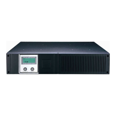
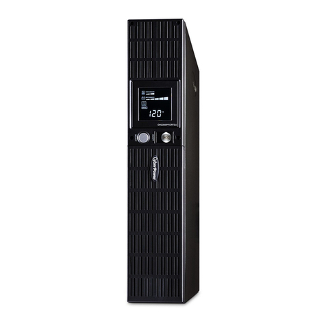
Figure1TheRackmountUPSfrontview

6
Figure2TheRackmountEBPfrontview
2Safety Warnings
IMPORTANT SAFETY INSTRUCTIONS
SAVE THESE INSTRUCTIONS
Thismanualcontainsimportantinstructionsthatyoushouldfollowduring
installationandmaintenanceoftheUPSandbatteries.Pleasereadallinstructions
beforeoperatingtheequipmentandsavethismanualforfuturereference.
DANGER
TheUPScontainsLETHALVOLTAGES.Allrepairsandserviceshouldbeperformed
byAUTHORIZEDSERVICEPERSONNELONLY.ThereareNOUSERSERVICEABLE
PARTSinsidetheUPS.
WARNING
zTheUPScontainsitsownenergysource(batteries).TheUPSoutputmaycarry
livevoltageevenwhentheUPSisnotconnectedtoanACsupply.
zToreducetheriskoffireorelectricshock,installtheUPSinatemperatureand
humiditycontrolled,indoorenvironment,freeofconductivecontaminants.
Ambienttemperaturemustnotexceed40°C(104°F).Donotoperatenearwater
orexcessivehumidity(90%maximum).
zToreducetheriskoffire,connectonlytoacircuitprovidedwithbranchcircuit
overcurrentprotectioninaccordancewiththeNationalElectricalCode(NEC),
ANSI/NFPA70.
zOutputovercurrentprotectionanddisconnectswitchmustbeprovidedby
others.
zTocomplywithinternationalstandardsandwiringregulations,thesumofthe
leakagecurrentoftheUPSandthetotalequipmentconnectedtotheoutputof
theUPSmustnothaveanearthleakagecurrentgreaterthan3.5milliamperes.
zIfinstallingoptionalrackmountEBP(s),installtheEBP(s)directlybelowtheUPS
sothatallwiringbetweenthecabinetsisinstalledbehindthefrontcoversandis
inaccessibletousers.ThemaximumnumberofEBP(s)perUPSisfour.
zIftheUPSrequiresanytypeoftransportation,verifythattheUPSisunplugged
andturnedoffandthendisconnecttheUPSinternalbatteryconnector.
CAUTION
zBatteriescanpresentariskofelectricalshockorburnfromhighshort-circuit
current.Observeproperprecautions.Servicingshouldbeperformedby
qualifiedservicepersonnelknowledgeableofbatteriesandrequired

7
precautions.Keepunauthorizedpersonnelawayfrombatteries.
zProperdisposalofbatteriesisrequired.Refertoyourlocalcodesfordisposal
requirements.
zNeverdisposeofbatteriesinafire.Batteriesmayexplodewhenexposedto
flame.
3Installation
Thissectionexplains:
zEquipmentinspection
zUnpackingthecabinet
zCheckingtheaccessorykit
zCabinetinstallation
zWiringinstallation
zInitialstartup
Inspecting the Equipment
Ifanyequipmentreceivedhasbeendamagedduringshipment,keeptheshipping
cartonsandpackingmaterialsforthecarrierorplaceofpurchaseandfileaclaimfor
shippingdamage.Ifyoudiscoverdamageafteracceptance,fileaclaimfor
concealeddamage.
Tofileaclaimforshippingdamageorconcealeddamage:1)Filewiththecarrier
within15daysofreceiptoftheequipment;2)Sendacopyofthedamageclaim
within15daystoyourservicerepresentative.
NOTE Check the battery recharge date on the shipping carton label. If the date has expired and the
batteries were never recharged, do not use the UPS. Contact your service representative.
Unpacking the Cabinet
CAUTION
zUnpackingthecabinetinalow-temperatureenvironmentmaycause
condensationtooccurinandonthecabinet.Donotinstallthecabinetuntilthe
insideandoutsideofthecabinetareabsolutelydry(hazardofelectricshock).
zThe cabinetisheavy(seepage44).Becarefultounpackandmovethecabinet.
Carefullytomoveandopenthecarton.Keepthecomponentspackageduntil
readytoinstall.
Tounpackthecabinetandaccessories:
1.Opentheoutercartonandremovetheaccessoriespackagedwiththecabinet.
2.Carefullyliftthecabinetoutoftheoutercarton.
3.Discardorrecyclethepackaginginaresponsiblemanner,orstoreitforfuture
use.
Placethecabinetinaprotectedareathathasadequateairflowandisfreeof
humidity,flammablegas,andcorrosion.
Checking the accessories
Itincludes:
zUPSuser'sguide
zSoftwareSuiteCD

8
zUSBcable
zPowercord(Inputandoutput)
zRS232cable
zIfyouorderedanoptionalExtendedBatteryModule(EBP),verifythatthefollowingadditional
itemisincludedwiththeEBP:
●EBPuser'sguide
NOTEDiscardtheEBPuser'sguideifyouareinstallingtheEBPwithanewUPSatthesametime.Use
theUPSuser'sguidetoinstallboththeUPSandtheEBP.
Rackmount Installation
TheRackmountcabinetcomeswithallofthehardwarerequiredforinstallationina
standardEIAorJISseismicRackmountconfigurationwithsquareandroundmountingholes.
Therailassembliesadjusttomountin19”rackswithadistancefromfronttoreararound
70~76cm(27to30inches)deep.
CheckingtheRailKitAccessories(Options)
Verifythatthefollowingrailkititemsareincludedforeachcabinet:
zLeftrailassembly:
-Leftrail
-Rearrail
-(3)M5_8pan-headscrews
zRightrailassembly:
-Rightrail
-Rearrail
-(3)M5_8pan-headscrews
zRailhardwarekit:
-(8)M5butterflynuts
-(2)rearstopbrackets
-(8)M5umbrellanuts
zMountingbracketkit:
-(2)mountingbrackets
-(8)M4_8flat-headscrews
ToolsRequired
Toassemblethecomponents,thefollowingtoolsmaybeneeded:
zcross-shapedscrewdriver
zand6mmwrenchorsocket
Rackmount Setup
CAUTION
z
The
cabinetisheavy.Removingthecabinetfromitscartonrequiresa
minimumoftwopeople.
z
IfinstallingoptionalEBP(S),makesuretoinstalltheEBP(S)directlybelowthe
UPSsothatallwiringbetweenthecabinetsisinstalledbehindthefrontcovers
andinaccessibletousers.
NOTE
Mountingrailsarerequiredforeachindividualcabinet

9
Toinstalltherailkit:
1.AssembletheleftandrightrailstotherearrailsasshowninFigure3.Donottightenthescrews.
Adjusteachrailsizeforthedepthofyourrack.
Figure3Securing the Rails
2. SelectthepropersizeintherackforpositioningtheUPS(seeFigure4).Therailoccupiesfour
positionsonthefrontandrearoftherack.
3. TightenfourM5UmbrellaNutsinthesideofrailassembly(seeFigure3).
4. FixonerailassemblytothefrontoftherackwithoneM5×12pan-headscrewandoneM5cage
nut.UsingtwoM5cagenutsandtwoM5×12pan-headscrews,tofixtherailassemblytotherear
oftherack.
Figure4FixingtheRails
5. RepeatSteps3and4fortheotherrailassembly.
6. Tightenthefourbutterflynutsinthemiddleofeachrailassembly.
7. Ifinstallingoptionalcabinets,repeatStep1throughStep6foreachrailkit.
8. PlacetheUPSonaflat,stablesurfacewiththefrontofthecabinetfacingtoyou.

10
9. AlignthemountingbracketswiththescrewholesoneachsideoftheUPSandfixwiththe
suppliedM4×8flat-headscrews(seeFigure5)
Figure5InstallingtheMountingBrackets
10. Ifinstallingoptionalcabinets,repeatStep8and9foreachcabinet.
11. SlidetheUPSandanyotheroptionalcabinetsintotherack.
12. SecurethefrontoftheUPStotherackusingoneM5×12pan-headscrewsandoneM5cagenuts
oneachside(seeFigure6).Installthebottomscrewoneachsidethroughthebottomholeof
mountingbracketandthebottomholeoftherail.
Repeatforanyoptionalcabinets.
Figure6SecuringtheFrontoftheCabinet
13.Continuetothefollowingsection,“RackmountWiringInstallation.
RackmountWiringInstallation
Thissectionexplains:
zInstallingtheUPS,includingconnectingtheUPSinternalbatteries
zConnectinganyOptionalEBP(S)

11
InstallingtheUPS
NOTE
Donotmakeunauthorizedchangestotheups;otherwise,damagemayoccur
toyourequipmentandvoidyourwarranty.
NOTE
Donotconnecttheupspowercordtoutilityuntilafterinstallationis
completed.
ToinstalltheUPS:
1.RemovethefrontcoverofeachUPS
HoldthecoverpartwithoutLCDontherightsideandextractit(seeFig.7)
Figure7ExtractUPSfrontcover
CAUTI
2.Connecttheinternalbatteryconnector(seeFigure8)
Connectredtored,Presstheconnectortightlytogethertoensureaproperconnection.
Remarks: Please note above step 1 & 2 only for replacing batteries or adding the internal batteries.
The plug will be connected properly if the UPS is with batteries installed.
CAUTION:Asmallamountofarcingmayoccurwhenconnectingtheinternalbatteries.Thisisnormal
andwillnotharmpersonnel.Connectthecablesquicklyandfirmly.

12
Figure8ConnectingtheUPSInternalBatteries
3.IfyouareinstallingEBPS,seethefollowingsection,“ConnectingtheEBP(s),”beforecontinuing
withtheUPSinstallation.
4.ReplacetheUPSfrontcover.
Toreplacethecover,verifytheEBPcableisroutedthroughtheknockoutonthebottomofthecover
ifEBPSareinstalled.
Putthefrontcoverhooksofsidewithdisplaytothecoverport,putanothersidetotheothertwo
ports,thenpressituntilthecoverandthechassisarecombinedtightly.
Figure9

13
5.Ifyouareinstallingpowermanagementsoftware,connectyourcomputertooneofthe
communicationportsoroptionalconnectivitycard.Forthecommunicationports,useanappropriate
cable.
6.Ifyourrackhasconductorsforgroundingorbondingofungroundedmetalparts,connectthe
groundcable(notsupplied)tothegroundbondingscrew.See“RearCovers”forthelocationofthe
groundbondingscrewforeachmodel.
7.Ifanemergencypower-off(disconnect)switchisrequiredbylocalcodes,see“RemoteEmergency
Power-off”(REPO)toinstalltheREPOswitchbeforepoweringontheUPS.
8.Continueto“UPSInitialStartup”.
ConnectingtheEBP(s)
ToinstalltheoptionalEBP(s)foraUPS:
1.RemovethefrontcoverofeachEBPandUPS(seeFigure10).
Itisthesamewiththeinstallationofthefrontcover.(Refer”ToinstalltheUPS“)
Figure10RemovingtheEBPFrontCover
2.OnthebottomoftheUPSfrontcover,removetheEBPcableknockout(seeFigure11).
Figure11RemovingtheUPSCableKnockout
3.Forthebottom(oronly)EBP,removetheEBPcableknockoutonthetopoftheEBPfrontcover.See
Figure12forthelocationofthetopEBPcableknockout.
4.IfyouareinstallingmorethanoneEBP,foreachadditionalEBPremovetheEBPcableknockouton
thetopandbottomoftheEBPfrontcover.SeeFigure12forthelocationoftheEBPcableknockouts.

14
CAUTION
AsmallamountofarcingmayoccurwhenconnectinganEBPtotheUPS.Thisisnormalandwillnot
harmpersonnel.InserttheEBPcableintotheUPSbatteryconnectorquicklyandfirmly.
5.PlugtheEBPcable(s)intothebatteryconnector(s)asshowninFigure12.UptofourEBPSmaybe
connectedtotheUPS.Connectblacktoblack,.Presstheconnectortightlytogethertoensurea
properconnection.
ToconnectasecondEBP,uncliptheEBPconnectoronthefirstEBPandpullgentlytoextendthe
wiringtotheEBPconnectoronthesecondEBP.RepeatforanyadditionalEBPS.
6.VerifythattheEBPconnectionsaretightandtheadequatebendradiusandstrainreliefexistfor
eachcable.
Figure12TypicalEBPInstallation
7.ReplacetheEBPfrontcover.
Toreplacethecover,verifythattheEBPcablesareroutedthroughtheEBPcoverknockouts,cover
connectswiththecoverhookneartheleftsideoftheEBPcabinet.RepeatforeachadditionalEBP.
Itisthesamewiththeinstallationofthefrontcover.(Refer”toUPSinstallation”)
8.VerifythatallwiresconnectedbetweentheUPSandEBP(s)areinstalledbehindthefrontcovers
andnotaccessibletousers.
9.ReturntoStep4tocontinuetheUPSinstallation.

15
RackmountconvertedtoTower Installation
1.RackmountconvertedtoTowerplasticbaseinstallation
①twoplasticbasebrackets②flattenitafterintercrossing
intercrossasfollowingFigure
Figure13plasticbaseinstallation
③IfanEBPisneededtobeplacedinthemiddle,theassemblyofplasticbaseissimilar,
Thedifferenceisthattwo1Uplasticbaseextendedboardsareaddedinthemiddle.(asthefollowing
shows)
(A)(B)
(C)(D)

16
(E)(F)
Figure14increaseEBPplasticbaseinstallation
2.TheinstallationbetweenUPSandEBPScanbereferredtoFig.15

17
Figure15TheinstallationforUPSandbatterybox
1.Installthebase,thenplacetheRTUPSonthebaseonebyoneasFig.15shows.
2.ThecoverinstallationandcableconnectionoftheUPSandEBPSarethesameasRT.(Toinstallthe
optionalEBP(s)foraUPS)
UPS Initial Startup
TostartuptheUPS:
NOTEVerifythatthetotalequipmentratingsdonotexceedtheUPScapacityto
preventanoverloadalarm.
1.IfoptionalEBPsareinstalled,verifythattheEBPsareconnectedtotheUPS.
2.PlugtheequipmenttobeprotectedintotheUPS,butdonotturnonthe
protectedequipment.
3.Makeanynecessaryprovisionsforcordretentionandstrainrelief.
4.PlugthedetachableUPSpowercordintotheinputconnectorontheUPSrear
cover.
5.PlugtheUPSpowercordintoapoweroutlet.TheUPSfrontcoverdisplay
illuminates.
6.TheUPSwilldoself-testwhenpoweron.Afterthat,thechargerwill
chargethebattery.IftheoutputdisplayedonLCDis“0”,thereisnooutput.If
youneedtheUPSoutputtheutilitywithoutstartingtheUPSwhenpluginto
theutility,youneedtosetbPSoptionto“ON”onthesettingmode,referto
Page26.

18
7.PressthecombinationstartupbuttonsontheUPSfrontcoverforatleasthalfa
second.TheUPSwillstartupandtheLEDwillturnonandoffsequentially.
8.ChecktheUPSfrontcoverdisplayforactivealarmsornotices.Resolveany
activealarmsbeforecontinuing.SeeTroubleshooting”onpage49.Ifthe
indicatorison,donotproceeduntilallalarmsareclear.ChecktheUPS
statusfromthefrontcovertoviewtheactivealarms.Correctthealarmsand
restartifnecessary.
10.Verifythattheindicatorilluminatessolid,indicatingthattheUPSis
operatingnormallyandanyloadsarepowered.
11.IfoptionalEBPsareinstalled,see“ConfiguringBatterysettings”onpage28to
setthenumberofinstalledEBPs.
12.Tochangeanyotherfactory-setdefaults,see“Usersettings”onpage25.
NOTE:Atinitialstartup,theUPSsetssystemfrequencyaccordingtoinputline
frequency(inputfrequencyauto-sensingisenabledbydefault).
NOTE:Atinitialstartup,pleasesettheoutputvoltageneededbeforestartupthe
UPS,Afterthesubsequentstartup,theUPSwilloutputthesettingvoltage.
13.IfyouinstalledanoptionalEPO,testtheEPOfunction:Activatetheexternal
EPOswitch.VerifythestatuschangeontheUPSdisplay.Deactivatethe
externalEPOswitchandrestarttheUPS.
NOTE:Theinternalbatterieschargeto80%capacityinlessthan5hours.However,
werecommendthatthebatteriesshouldbechargedfor48hoursafterinstallation
orlong-termstorage.IfoptionalEBPsareinstalled,seetherechargetimeslistedin
Tabl e 21onpage48.

19
4.Operation
ThischaptercontainsinformationonhowtousetheUPS,includingfrontcoveroperation,
operatingmodes,UPSstartupandshutdown,transferringtheUPSbetweenmodes,and
configuringbypasssettings,loadsegments,andbatterysettings.
Control Cover Functions
TheUPShasathree-buttonsegmentalLCDwithbacklight.Itprovidesusefulinformationabout
theUPSitself,loadstatus,measurements,andsettings(seeFigure16).
Figure16.ControlCover
Table1.IndicatorDescriptions
Indicator
Description
Red
On TheUPShasanactivealarmorfault.
Yellow
On TheUPSisinBypassmode.
TheUPSisoperatingnormallyonbypass
duringHighEfficiencyoperation.
Yellow
OnTheUPSisinBatterymode.
Green
On TheUPSisoperatingnormally.
NOTE Whenpoweronorstartup,theseindicatorswillturnonandoff
sequentially.
NOTEOndifferentoperationmodes,theseindicatorswillindicatedifferently.
RefertoTa ble 7.
This manual suits for next models
3
Table of contents
Other PSS UPS manuals
Popular UPS manuals by other brands
ABB
ABB HiPerGuard MV UPS user manual
CyberPower
CyberPower PR1000LCDRTXL2U user manual
Uninterruptible Power System
Uninterruptible Power System 400 user manual
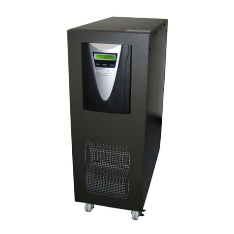
Powertronix
Powertronix PTX2-A3 Service manual
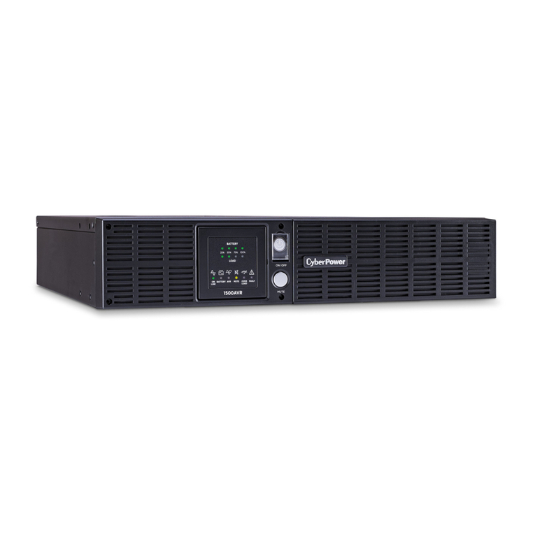
CyberPower
CyberPower AVR Series user manual
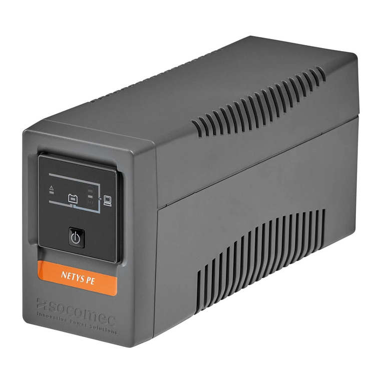
socomec
socomec NETYS PE Installation and operating manual
