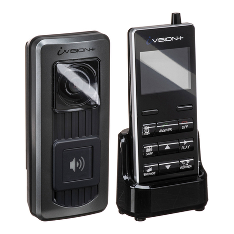
PST PST-VD07H-ID User manual


2
Contents
Preface ...................................................................................................2
1. Parameter ...........................................................................................3
2. The Instruction ....................................................................................3
2.1 Outdoor Station .................................................................................3
2.2 Indoor Unit ........................................................................................6
2.3 Power Supply ....................................................................................9
3. Wiring Diagram ...................................................................................9
4. Remote control .................................................................................10
5. Warning ......................................................................................................12

3
Preface
Thank you for using our products. Hope our products and services
can bring convenience and happiness to your life.
Video Door Phone for villa
single family house, single apartment.
1) Connect with CAT 5e ( UTP—Unshielded Twisted Pair )
2) CAT 5e transmit audio signal, RS487 communication, video
signal.
3) Access control function: ID/ IC cards
4) Support to connect electric lock
To obtain the best performance and ensure years of trouble-free
use before operating it, please read this instruction manual
carefully.

4
1. The Parameter
Outdoor
Station
Installation
Flush-mount
Voltage
DC18V±10% (Working)
Current
≤70mA (Working); ≤15mA (Standby)
Indoor Unit
Installation
Wall-mount
Voltage
DC18V±10% (Working)
Current
≤ 300mA (Working); ≤20mA (Standby)
Wiring
requirements
Connection: CAT5e / Cat6 Cable ( normal network cable )
Power line : RVV2 * 0.75
Lock line : RVV2 * 0.75
2. The Instruction
2 .1 Outdoor Station
①Microphone: Talk
②Card Reader: ID card / key fob
③Night Vision: 6 IR lights /white LED lights
④Call Button: Press it to call a household
⑤Camera: 580TVL CMOS camera , 98°Wide Angle
⑥Speaker: Two protective net behind the hole
Features:
※Waterproof: IP54
※Rain shade
※Unlock by ID cards, key fob
※2-way audio intercom
※CAT 5e/ CAT 6e network cable for connection between outdoor station to
indoor unit
※Transmission Distance: 30m ~ 200m
※One Outdoor Station is compatible to 4 indoor units at maximum.

5
Figure 1 The Backside of Outdoor Station
※Green & grey wire: lock line
※RJ45: Connection for Network Cable ( CAT5e )
Wire Connection
Noted:
(1) Do not shake, collide, smash, punch the device;
(2) Do not install the Outdoor Station in the following places:
※Under long-time sunshine;
※40 Fahrenheit;
※Under long-time snow and frost;
※Dusty;
(3) When electrified, if there is any unexpected situation
happened, please cut off power immediately until the fault is
removed.
(4) If it is in abnormal status, cut off power first. And check it
carefully. Any malfunctioning fault, please contact with supplier
and do not try to repair by your own.
(5)Do not wash and fold card reader.

6
Figure 2 The Outdoor Station of Installation
Installation requirements
(1) Match the fix hole in the wall and the fixing box. If the outdoor station
is embedded in the wall, in order to prevent the expansion of cement,
please make the hole in wall or door is bigger(5mm) than the box.
(2) Put the bottom box fixed in the hole of the door or wall.
(3) Connected with the network cable.
(4) Fix the outdoor station to the installation bottom box with a screw.

7
2.2 Indoor Unit
:Monitor key
:Unlock Door
:Send the information to the Guard Station
: ( ) Call Guard Station button
: Answer call
Operation introduction
A. A outdoor station is compatible to 4 indoor units at maximum. When
calls for indoor unit, all the indoor unit ring at the same time. The others
stop ringing after picking up one of it.
B. When the indoor unit is called, it will show images on the screen.
Press “Answer call” , confirm it and press “Unlock Door” .
( To unlock the door, please press first, then press )
C. When the indoor unit is called, it will stop ringing in 90 seconds
without answering.
D. When in standby mode, press “ Monitor key ” to monitor
outside.
And stop automatically in 90 seconds .

8
Figure 3 The Indoor Station of Installation
Adjust the Color & Brightness
A. Under normal state, press “Monitor” button and then “Answer ” button
to enter into adjustment of page.
B. "Monitor”: Home key; Contrast adjustment, Brightness adjustment.
C. “Answer” button”: minus; “Unlock Door” button: add.
D. Press “Monitor” button to adjust brightness. “Answer” button
represents minus
brightness; “Unlock Door” button represents add brightness.
E: Memory function: After setting by one time, the indoor unit has the
memory.

9
Failure analysis and troubleshooting
Failure
Inspection object
Troubleshooting
Can not call & be
called
Check whether the connection o
f indoor units’ power
lines is good
Connect the power lines correctly
to make the light’s on
Not ring after being
called
Check the speaker, music chip
and peripheral circuit
Replace music chip
The screen doesn’t
work
Check the control module and
circuit
Correctly connect the power
lines , or replace the other indoor
units
Can be called, but
cannot
Check whether microphone is
damaged or poor contact
Replace microphone
2.3Power supply
(1) Adapter : supplied power for outdoor station and indoor unit.
(2) Power supply: supplied power for outdoor station, distributor, E-lock.
3. Wiring Diagram
Figure 4 The wiring diagram

10
4. Remote control
4.1 Entering system
Press “ *XXXX# ” →CALL →Green light is on. (XXXX is the initial code
“1234”.)
4.2 Add user card
Press “ *11# ” →CALL →Green light flashes →Swipe user cards
continuously.
Press “ *# ” →CALL →Green light is off →End.
4.3 The operation of adding user card and function of unlocking
(When the card reader is broken down, after changed a new card reader,
users will use their own user cards to swipe to add user cards and unlock
the door.)
Press “ *13# ” →CALL →Green light flashes →Swiping user
cards continuously. (This process will not exit automatically.)
Press “ *# ” →CALL→Green light is off →End.
4.4 Add user card
Press “ *12# ” →CALL →?????????????? →#CALL
(??????????????: means the 14 digit numbers on user card.)
Press “ EXIT” to exit the process.
If the user card is successfully added →Beep, Beep
If not →Beep, Beep Beep
4.5 Delete user card by swiping cards
Press “*21#” →CALL →Green light is on.
Press “*#” →CALL →Green light is off →End.

11
4.6 Delete card
Press “ *22# ” →CALL →?????????????? →#CALL
(??????????????: means the 14 digit numbers on user card.)
Press Exit to exit the process. If it is successfully deleted, the buzzer
sounds “Bi-Bi-”; if it is not, the buzzer will sounds “Bi-Bi-Bi-”.
4.7 Delete all user cards
Press “*23#” →CALL →Green light is on →Beep, Beep (continuously)
Until the buzzer stops (about 5 minutes) →End.
4.8 Unlock the door
Press “ *53# ” →CALL →Green light is on.
4.9 To set the door is always opened
Press “ *51# ” →CALL
4.10 To return to normal state
Press “ *54# ” →CALL →the door is always locked.
4.11 Press “*6#” -->CALL, exit all process
When there is a wrong entering by remote control, press “ EXIT” to exit the
process and enter into the process again. For example:
Entering the initial code “*1234#” →CALL →enter into the system; but you
entered “ *1111# ” →CALL.
You shall press “ EXIT ” to exit and enter “ *1234# ” →CALL again.

12
5. Warning
※Avoid sharp dropping or knocking.
※The image can be illegible for the direct sunshine on the video camera.
※Do not install the product in a humid place. It may cause an electric shock or a
fire.
※Do not touch the units with wet hand. Do not use water, thinner or a detergent
to wash the units. It may cause breakdown and electric shock.
※Do not open the monitor or video camera.
※Do not put the plug in the socket simultaneously.
※Do not connect to other products, such as TV etc. It may cause breakdown.
※Do not disassemble, repair or modify the product.It may cause a fire ,an electric
shock or an injury to malfunction of the product.
※Do not forcibly pull out the cord from the socket. If the cord is damaged, it may
cause a fire or an electric shock.
Table of contents
Other PST Intercom System manuals
