PST MICHELL Instruments ADG400 User manual

ADG400
Advanced Dew-Point Generator
User Manual
99998 Issue 1
November 2022

Please ll out the form(s) below for each instrument that has been purchased.
Use this information when contacting Michell Instruments for service purposes.
Product Name
Order Code
Serial Number
Invoice Date
Installation Location
Tag Number
Product Name
Order Code
Serial Number
Invoice Date
Installation Location
Tag Number
Product Name
Order Code
Serial Number
Invoice Date
Installation Location
Tag Number

© 2022 Michell Instruments
This document is the property of Michell Instruments Ltd and may not be copied or
otherwise reproduced, communicated in any way to third parties, nor stored in any Data
Processing System without the express written authorization of Michell Instruments Ltd.
For Michell Instruments' contact information please go to
www.michell.com
ADG400

ADG400 User Manual
iv 99998 Issue 1, November 2022
1 INTRODUCTION ................................................................................................1
1.1 Features ............................................................................................................ 1
1.2 Theory of Operation ........................................................................................... 2
2 INSTALLATION ..................................................................................................3
2.1 Unpacking the Instrument ................................................................................... 3
2.2 Power Supply ..................................................................................................... 3
2.3 USB Connection.................................................................................................. 3
2.4 Dry Gas Supply .................................................................................................. 3
2.5 Gas Connections ................................................................................................. 4
2.6 Typical Setup ..................................................................................................... 4
3 OPERATION ......................................................................................................5
3.1 First-time Operation ............................................................................................ 5
3.2 Typical Calibration Run ....................................................................................... 5
3.3 HMI ................................................................................................................... 6
3.4 Screensaver ....................................................................................................... 6
3.5 Main Screen ....................................................................................................... 7
3.6 Modes of Operation ............................................................................................ 8
3.6.1 Manual Mode ................................................................................................ 8
3.6.1.1 Set Point Picker ....................................................................................... 9
3.6.2 Prole Mode ................................................................................................. 9
3.6.3 Remote Mode ............................................................................................. 10
3.6.3.1 Remote Mode Commands ...................................................................... 11
3.6.4 Remote Access ........................................................................................... 12
3.6.5 Installing and Using the Remote Access Software .......................................... 12
3.6.6 Status Page ................................................................................................ 13
3.6.6.1 Transition Delay .................................................................................... 14
3.6.7 Settings Menu ............................................................................................. 14
3.6.8 Set Point Editor ........................................................................................... 15
3.6.8.1 Converting MFC Values to ml/min Flow Rates .......................................... 16
3.6.8.2 Adjusting Set Points .............................................................................. 16
3.6.9 Prole Editor ............................................................................................... 17
3.6.10 Saturator Filling Mode ................................................................................. 18
3.6.10.1 Saturator Filling Instructions .................................................................. 19
4 MAINTENANCE ................................................................................................20
4.1 Inlet Particulate Filter ....................................................................................... 20
4.2 Fuses .............................................................................................................. 20
4.3 General Troubleshooting ................................................................................... 21
4.4 Emptying the Saturators for Transport ................................................................ 22
Contents
Safety ................................................................................................................................vi
Electrical Safety ..........................................................................................................vii
Pressure Safety ...........................................................................................................vii
Hazardous Materials (WEEE, RoHS3 & REACH) ..............................................................vii
Safe Handling .............................................................................................................vii
Repair and Maintenance ..............................................................................................vii
Safety Conformity .......................................................................................................vii
Abbreviations .................................................................................................................... viii

ADG400 User Manual
Michell Instruments v
Tables
Table 1 Minimum Stabilization Times ........................................................................6
Table 3 Read Command Response Explanation ........................................................11
Table 2 Supported Serial Commands ......................................................................11
Table 4 Span of Installed MFCs ..............................................................................16
Figures
Figure 1 Typical Setup Diagram ................................................................................4
Figure 2 Manual Mode .............................................................................................7
Figure 3 Prole Mode ...............................................................................................7
Figure 4 Main Screen in Manual Mode .......................................................................8
Figure 5 Set Point Picker Screen ...............................................................................9
Figure 6 Main Screen in Prole Mode ........................................................................9
Figure 7 Prole Selection Screen .............................................................................10
Figure 8 Main Screen in Remote Mode ....................................................................10
Figure 9 Main Screen Shown on a PC via Remote Access Software ............................12
Figure 10 Status Page Screen ...................................................................................13
Figure 11 Settings Screen ........................................................................................14
Figure 12 Set Point Editor Screen .............................................................................15
Figure 13 Prole Editor Screen .................................................................................17
Figure 14 Saturator Filling Screen .............................................................................18
Figure 15 Saturator Fill Levels ..................................................................................18
Figure 16 ADG400 with Open Front Panel .................................................................19
Figure 17 ADG400 Internal View ..............................................................................22
Appendices
Appendix A Technical Specications .............................................................................. 24
A.1 Dimensions .................................................................................25
Appendix B Quality, Recycling, Compliance & Warranty Information ................................ 27
Appendix C Return Document & Decontamination Declaration ........................................ 29

ADG400 User Manual
vi 99998 Issue 1, November 2022
Safety
The instrument is designed to be completely safe when installed and operated correctly in accordance
with the information provided in this manual.
This manual contains all the required information to install, operate and maintain this product. Prior
to installation and use of this product, this entire manual should be read and understood. Installation
and operation of this product should be carried out by suitably competent personnel only. The
installation and operation of this product must be in accordance with the instructions provided and
according to the terms of any associated safety certicates. Incorrect installation and use of this
product other than those described in this manual and other than its intended purpose will render
all warranties void.
This product meets the essential protection requirements of the relevant EU & UK directives. Further
details of applied directives may be found in the product specication.
Electricity and pressurized gas can be dangerous. This product must be installed and operated only
by suitable trained personnel.
!
No user serviceable parts inside
!
Where this hazard warning symbol appears in the following
sections, it is used to indicate areas where potentially hazardous
operations need to be carried out and where particular attention to
personal and personnel safety must be observed.
Where this symbol appears in the following sections it is used to
indicate areas of potential risk of electric shock.
This product is intended for use only under the following conditions:
a. indoor use
b. altitude up to 2,000 m
c. temperature 5 °C...40 °C
(refer to Appendix A, Technical Specication, for Operating Temperature range)
d. maximum relative humidity 80 % for temperatures up to 31 °C decreasing
linearly to 50 %, relative humidity at 40 °C
e. MAINS supply voltage uctuations up to ±10 % of the nominal voltage
f. TRANSIENT OVERVOLTAGES up to the levels of OVERVOLTAGE CATEGORY ll
g. TEMPORARY OVERVOLTAGES occurring on the MAINS supply
h. applicable POLLUTION DEGREE 2 of the intended environment

ADG400 User Manual
Michell Instruments vii
Electrical Safety
Ensure electrical safety is complied with by following the directions provided here and observing all
local operation & installation requirements at the intended location of use.
This product is completely safe when using any options and accessories supplied by the manufacturer
of this product for use with it. Refer to Section 2 (Installation) of this manual for further details.
Pressure Safety
For this product to operate satisfactorily, pressurized gas must be connected to it. Observe all the
information contained within this manual and all local operation & installation requirements at the
intended location of use. Refer to Section 2 (Installation) of this manual for further details.
Hazardous Materials (WEEE, RoHS3 & REACH)
This product does not contain or release any prohibited chemicals listed on the SVHC (Substances
of Very High Concern) Candidate List. During the intended normal operation of this product it is not
possible for the user to come into contact with any hazardous materials. This product is designed to
be recyclable except where indicated.
Safe Handling
Appropriate lifting and handling techniques should be used when moving and installing the ADG400.
• The total weight of the product is 23 kg (51 lb).
• Before commencing any lifting or handling, ensure that the intended
location is suitable and is appropriately prepared.
• A clear path to the intended location should be made and appropriate
lifting aids used (e.g. a suitably rated trolley).
• Due to the bulky nature and weight of the product, it is recommended
that two people perform all handling operations.
• Be aware that saturators should be emptied of water before transporting
the ADG400. See Section 4.4 for instructions.
Repair and Maintenance
The instrument must be maintained either by the manufacturer or an accredited service agent. For
contact information, visit the website at www.michell.com.
Safety Conformity
This product meets the essential protection requirements of the relevant EU & UK directives. Further
details of applied standards may be found in Appendix B.

ADG400 User Manual
viii 99998 Issue 1, November 2022
Abbreviations
The following abbreviations are used in this manual:
barg pressure unit (=100 kP or 0.987 atm) (bar gauge)
°C degrees Celsius
°F degrees Fahrenheit
DC direct current
g grams
in inch(es)
µm micrometer
m/sec meters per second
mA milliampere
mm millimetres
MPa megapascal
Nl/min normal liters per minute
Nm Newton meter
oz ounces
psig pounds per square inch
RH relative humidity
scfh standard cubic feet per hour
fps feet per second
T temperature
V Volts
Ω Ohms
ø diameter

ADG400 User Manual
Michell Instruments 1
INTRODUCTION
1 INTRODUCTION
The ADG400 is designed for use as part of a hygrometry calibration system. It is capable
of repeatable generation of dew points across a range of -80 °C...+20 °C, when used in
conjunction with the Michell Instruments PSD2 pressure swing dryer.
The generator is based on the volumetric mixing of dry and wet gases. It gives the
fastest response when changing between set points in comparison to other dew-point
generator technologies (such as two-temperature, two-pressure or a combination of
both).
The controller comes pre-programmed with a standard table of dew-point set points,
from -80 °C to +20 °C at 10 °C intervals. The table contains ow rates for each of the 5
MFCs, along with solenoid settings that determine if 1 or 2 stage mixing is used. A user
table is also provided allowing up to 13 user-dened setpoints to be stored.
There are 3 modes of operation: Manual mode for push-button selection of set-points,
Prole mode for automatic timed changing of set-points, and Remote mode for changing
of set-points via serial commands sent over the USB port for integration with customer
software. Further to this, the ADG HMI can be displayed and interacted with on a PC
connected via the USB interface.
The ADG400 is designed to be used in conjunction with a high accuracy reference
instrument such as a Michell Instruments S8000 RS.
1.1 Features
The key features of the ADG include:
• Full-color touch-screen HMI
• 11-point factory-programmed dew-point setpoint table from -80 to +20 °C
at 10 °C intervals
• 13-point user programmable dew-point setpoint table
• 3 programmable 13-point automatic calibration proles with customizable
timings
• Change set points using serial commands via built-in USB port
• Remote Access mode allows HMI to be operated using a connected PC
• Temperature-controlled enclosure to ensure output stability and repeatability

ADG400 User Manual
299998 Issue 1, November 2022
INTRODUCTION
1.2 Theory of Operation
Dried air is supplied to the ADG – some of this dry air is used as-is for mixing, and
some is diverted through the two saturators. Each saturator is lled with distilled or
demineralized water, and the dry air stream is bubbled through this water via a sintered
nozzle, which creates a stream of wet air that can be used for mixing. Each saturator
is followed by a water trap which is necessary to prevent water from escaping the
saturation system when it is pressurized/depressurized.
The rst mixing stage comprises 3 high-precision mass-ow controllers. One MFC
controls the dry air ow from the external dry air source. The other 2 MFCs give coarse
and ne control of the wet air from the saturators. This stage enables dew points from
+20 °C to -20 °C to be generated.
The second mixing stage comprises of 2 further MFCs. One MFC controls a ow of dry
air from the external dry air source. The second MFC controls the ow of air from the
rst stage. This second mixing stage enables dew points from -30 to -80 °C.

ADG400 User Manual
Michell Instruments 3
INSTALLATION
2 INSTALLATION
2.1 Unpacking the Instrument
On delivery, please check that all the following standard components are in the packing box:
• ADG400 Dew-Point Generator
• IEC Power Cable
• USB-B Cable
2.2 Power Supply
The ADG400 is tted with a switch-mode power supply that can accept mains power
90...264 V AC, 47...63 Hz via the IEC power connection.
The ADG400 is tted with a 10 A 20 x 5 mm (T) fuse located behind a fuse cover next
to the IEC power connection.
2.3 USB Connection
A USB type-B port is tted to the back of the instrument to enable remote access to the
HMI from a PC or changing set-points via serial commands.
Refer to
Section 3.6.3, Remote Mode
, and
Section 3.6.4, Remote Access
, for more
information.
2.4 Dry Gas Supply
The generator requires a supply of high-quality (oil free) dry gas with a moisture
content of <0.5 ppmV (<-80 °C atmospheric dew point) or compressed air to the same
specication as used during its setup/calibration. This enables the maximum range of
dew points to be generated.
A minimum ow of 7 Nl/min (14.8 scfh) is required, delivered at a pressure of 2.0 barg
(29.0 psig).
If replacing an existing dew-point generator connected to a PSD2, the internal pressure
regulator of the PSD2 MUST be adjusted to 2.0 barg (29.0 psig), otherwise the
ADG400 will not function. Refer to the latest PSD2 manual from the PST website (www.
processsensing.com) for instructions on how to perform this adjustment.
The generator was set up/calibrated using either a Michell PSD2 Pressure Swing Dryer
or a specic compressed air supply. A warning label, stipulating what the air inlet
specication needs to comply with, appears on the rear panel of the generator.
WARNING!
COMPLY WITH AIR INLET SPECIFICATION
TO ENSURE ACCURATE OPERATION
Air Inlet Specication:
Pressure = 2.00 BarG (29 PsiG)
Dew Point = -85 °C @ 1.013 BarA

ADG400 User Manual
499998 Issue 1, November 2022
INSTALLATION
2.5 Gas Connections
The gas inlet and outlet connections are Swagelok® 6 mm stainless-steel bulkhead
union tube ttings, located on the rear panel of the unit marked GAS IN and GAS OUT.
2.6 Typical Setup
The ADG should be used in conjunction with a Michell Chilled Mirror Reference Instrument.
A complete system would usually include:
• Dry air source (Michell Instruments PSD2)
• ADG400 Generator
• Chilled Mirror Reference Instrument with ow control valve
• Manifold for units under test with ow control valve
• Bypass leg for venting excess ow with ow control valve
Figure 1
Typical Setup Diagram

ADG400 User Manual
Michell Instruments 5
OPERATION
3 OPERATION
It is recommended to familiarize yourself with the installation, operation and maintenance
sections of this manual before using the product for the rst time.
3.1 First-time Operation
Before using the instrument for the rst time, the following steps should be taken.
1. Install the electrical and gas connections as per the instructions in
Section
2, Installation
.
2. Power-on the instrument.
3. Fill the saturators using the saturator lling mode – full instructions are
given in
Section 3.6.10
.
4. It is recommended to leave the generator set to DRYER mode and run
overnight before rst use.
Note: The generator is designed to be operated continuously and does not need to be
powered o. When not using the generator, it should be set to DRYER mode.
3.2 Typical Calibration Run
Dew-point calibrations should always run from the driest point to the wettest, with an
adequate purge being carried out at the beginning to reduce the moisture level of the
system, and all the units under test, to below the lowest point to be calibrated.
Prior to beginning a calibration, the following checks should be carried out:
1. Power-on the reference hygrometer.
2. Ensure all units under test are installed into calibration manifold and all
unused manifold ports are blanked o.
3. Check the saturator level and top up, if required, by initiating the saturator
lling mode.

ADG400 User Manual
699998 Issue 1, November 2022
OPERATION
A typical calibration to -80 °Cfp, for the Michell Instruments Easidew, would use the
following timings:
Set Point
(°C Dew/Frost Point) Minimum Stabilization Time
DRYER 48 hours
-80 12 hours
-70 8 hours
-60 4 hours
-50 2 hours
-40 1 hour
-30 1 hour
-20 1 hour
-10 1 hour
0 1 hour
+10 1 hour
+20 1 hour
Table 1
Minimum Stabilization Times
3.3 HMI
The ADG uses a 3.5" full-color touch-screen controller.
3.4 Screensaver
When idle for 10 minutes, the display of the ADG will be set to screensaver mode, which
dims the display. This helps to maintain the brightness of the backlight as the unit is
constantly powered on.
The length of time before the screensaver is active is congurable in the settings menu.

ADG400 User Manual
Michell Instruments 7
OPERATION
3.5 Main Screen
Figure 2
Manual Mode
Figure 3
Prole Mode
Item Description
Set Point
Indicates currently selected set point in all modes.
The indicator to the far right shows if the selected set point is from:
SStandard Table
UUser Table
Pressing the button will bring up the Set Point selection screen in
Manual mode.
Enclosure
Temperature
Displays the current enclosure temperature, which should be at 35 °C
±0.1 °C
? (Status
Button)
Displays the status screen.
Note: Entering the status screen will pause a running prole, until un-
paused by the user.
Mode Only available in Manual mode; allows the mode of operation to be set
to Prole or Remote.
Remaining
Shows the remaining time for the current prole set point in hh:mm:ss
format. Press the time button to pause/un-pause the prole.
Far-right indicator:
Green Prole running
Yellow Prole paused
Red Prole complete
Lock Only shown in Manual mode; locks the display with the xed passcode.
Stop Shown in Prole and Remote modes when a passcode is not set.
Returns to Manual mode, retaining the current set point.
Unlock Requires a passcode to unlock the display.
Returns to Manual mode, retaining the current set point.
Settings Only enabled in Manual mode; navigates to the Settings menu.
For information about locking the display with a passcode, refer to
Section 3.6.7,
Settings Menu
.

ADG400 User Manual
899998 Issue 1, November 2022
OPERATION
3.6 Modes of Operation
The modes of operations are:
• Manual mode: change set points by button press
• Prole mode: set points change automatically after a predetermined time
• Remote mode: set points are changed by serial command from a PC (for
software integration)
• Remote Access: the ADG is controlled from a PC using the HMI
When in Manual mode, the mode can be changed by pressing the Mode button.
When in Prole or Remote mode, the Stop button must be pressed to return to Manual
mode. The Stop button will be replaced with an Unlock button if passcode protection
is enabled.
3.6.1 Manual Mode
Pressing the Set Point button takes you to the set-point picker, enabling a new set point
to be selected.
Figure 4
Main Screen in Manual Mode

ADG400 User Manual
Michell Instruments 9
OPERATION
3.6.1.1 Set Point Picker
This is used to change the set point in Manual mode.
Item Description
Arrow Buttons < > Change the desired set point.
Standard Table /
User Table Button
Select a new set point from the displayed table. This is only
visible if the user-dened set points have been created.
Apply Apply the selected set point and return to the Main screen.
Back Return to the Main screen without changing the set point.
Figure 5
Set Point Picker Screen
3.6.2 Prole Mode
Prole mode runs one of three proles which contain a list of set points, each with an
associated duration. This allows unattended operation.
Figure 6
Main Screen in Prole Mode
To enter Prole mode, the Mode button is pressed from the Main screen. This takes you
to the Prole select screen, which allows one of the three prole presets to be loaded.

ADG400 User Manual
10 99998 Issue 1, November 2022
OPERATION
Figure 7
Prole Selection Screen
Selecting one of the prole presets will start the prole and return to the Main screen.
Pressing the Back button will lead back to the Main screen, leaving the ADG in Manual
mode.
Refer to
Section 3.6.9, Prole Editor
, for details on how to dene calibration proles.
3.6.3 Remote Mode
When connecting the ADG400 to a PC using the USB connection, it will appear as a
virtual serial port.
In Remote mode, set points can be changed via a serial command. This mode is designed
for integration with customer software. For remote control of the generator from a
PC, please see also
Section 3.6.4, Remote Access
, which may be more appropriate,
depending on the intended result.
In Remote mode, controls are disabled, including the Read MFCs button on the status
page, which is disabled to ensure a remote set-point change event cannot be interrupted.
The MFC Set Point and Measure values on the status page can only be updated using
the appropriate serial command.
Note: This cannot be used in conjunction with Remote Access, which relies on the same
serial port connection.
Figure 8
Main Screen in Remote Mode

ADG400 User Manual
Michell Instruments 11
OPERATION
3.6.3.1 Remote Mode Commands
The following commands are supported:
Command Description
SPxx<cr> Activate Set Point Index xx, where xx is a number from 00 to 13.
Set point is loaded from the standard set point table.
UPxx<cr> Activate Set Point Index xx, where xx is a number from 00 to 13.
Set point is loaded from the user set point table.
READ<cr> Returns the data string shown in the example below:
Table 2
Supported Serial Commands
READ command returned string:
I,5,S,0010,U,STD,SP,+06400+28800+00000+00000+00000,SP&MSR,+12801+12800+00000+00000+040
00+04000+30720+30720+10559+10560,H,+350,EOM
Component Description
I
5 Set Point Index
S
0010 Dew/Frost Point of Set Point (+10 °C)
U
STD Set Point Source Table (USR or STD)
SP
+06400+28800+00000+00000+00000 Target MFC Values
(S1Dry+S1Wet(C)+S1Wet(F)+S2Dry+S2Wet)
SP&MSR
+12801+12800+00000+00000+04000
+04000+30720+30720+10559+10560
Measured then Set Point Value for each MFC
12801 = S1Dry Measured
12800 = S1Dry Set-Point etc.
H
+350 Enclosure Temperature * 10 (35 °C)
EOM
Table 3
Read Command Response Explanation
Commands must be sent as a complete string and cannot by typed in letter by letter
using a terminal program.
Please contact your PST representative for an example software project, showing how
to implement the communications protocol.

ADG400 User Manual
12 99998 Issue 1, November 2022
OPERATION
3.6.4 Remote Access
The ADG can be controlled from a PC, providing full access to the user interface in
a desktop window, as shown below. Note: this cannot be used in conjunction with
Remote mode, which relies on the same serial port over USB connection.
Figure 9
Main Screen Shown on a PC via Remote Access Software
3.6.5 Installing and Using the Remote Access Software
1. Navigate to the Michell Instruments software download page:
http://www.michell.com/uk/support/sware-downloads.php
2. Download and install the ADG400 Remote Access package.
3. Restart the PC – this is essential, otherwise the software will not launch.
4. Launch the Remote Access software from the Start menu. It must be
"Run as Administrator".
Note: You should rst change the compatibility options for the shortcut to always "Run
as Administrator": rst, right click on the shortcut and select Properties, then navigate
to the Compatibility tab.
5. Set the OPLC model to the Samba 35 through the conguration menu.
6. From the same menu, select Communication – PC Settings and change
the "PC Port" to the appropriate COM port number for the ADG. This can
be found in Device Manager, under Ports.
7. Click the OnLine button to connect to the ADG.
Table of contents
Popular Portable Generator manuals by other brands
Generac Mobile
Generac Mobile MDE570 owner's manual
Honeywell
Honeywell 0061520 owner's manual
Kohler
Kohler OnCue Plus quick start guide
Champion Global Power Equipment
Champion Global Power Equipment 201228 quick start
Clarke
Clarke PG3800A Operation & maintenance instructions
OfficeSource
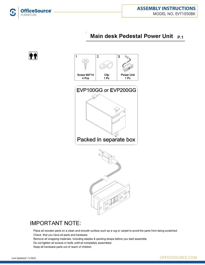
OfficeSource EVT1050BK Assembly instructions

