SAFETY INFORMATION
1. Keep the torch out of reach of children.
2. Read directions carefully before use.
3. The burn tip and other accessory tips get hot in operation.
Do not touch the tip or accessories, or place them on flammable objects.
4.
Always have a fire extinguisher or bucket of water near the torch work area.
5. Always point away from eyes and body when igniting or operating.
Flame is invisible in sunlight, it can cause injury if not used with extreme caution.
6. Under no circumstances should you attempt to repair a damage torch.
7.
Do not store under direct sunlight or anywhere that will exceed 104 ° F / 40 °C
8. Do not immerse in water.
9.
Make sure the adjustment knob is firmly closed and the flame is completely
extinguished after using.
If you hear a hissing sound the valve is open.
10.Use only in well ventilated areas.
OPERATION
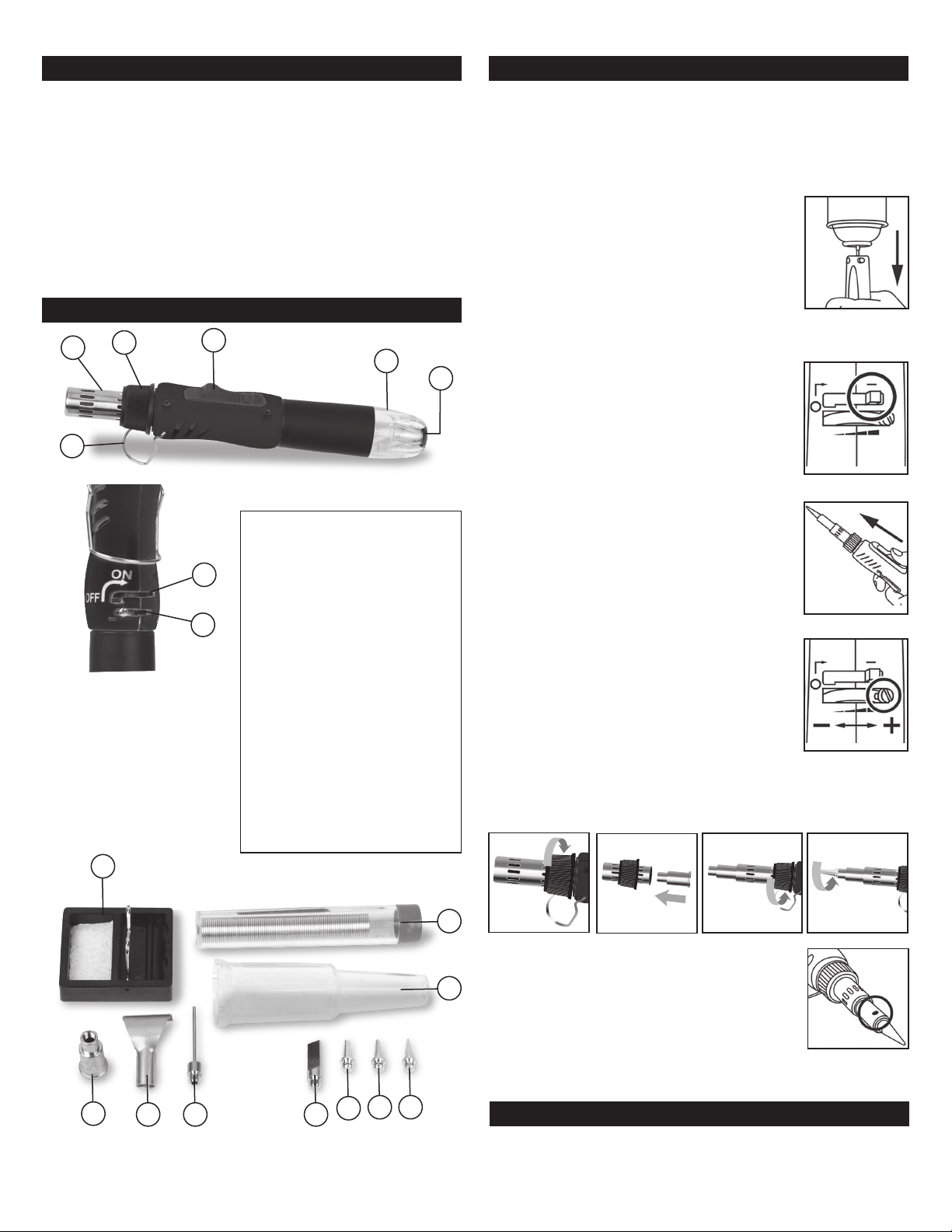
PARTS DESCRIPTION
123
4
5
6
7
8
1.........................Blow Torch Head
2...................Torch Head Retainer
3.............................Ignition Switch
4................................Butane Tank
5..................................Kick Stand
6..................................Filler Valve
7...........................ON/OFF Switch
8.....................Flame Level Adjust
9.........................Stand w/Sponge
10.................................Solder
11................................Safety Cap
12.................................Blower Tip
13..................................Scoop Tip
14..................Polyfoam Cutter Tip
15.............................Hot Knife Tip
16.............................Soldering Tip
17......................Double Edge Tip
18.......................Needle Point Tip
9
10
11
12 13 14 15 16 17 18
First time use:
When using the copper tip for the rst time, please
preheat the soldering iron to the temperature of the
solderable wire (about 30 seconds).
Filling Fuel Tank
1. Use only high quality butane gas.
2. Before filling make sure that the off / on switch is
turned to the “O” position.
3. Holding the appliance upside down insert the butane
gas refill nozzle vertically into the gas refill valve. (Fig. 1)
Push the butane gas refill nozzle down into the gas
refill valve until the fuel tank is full. (liquid gas will
escape from the gas refill valve.)
4. After filling the unit allow the gas to stabilize for a few
minutes before igniting.
Lighting
1. When igniting the torch ensure the torch is held in the
upright position.
2.
Turn the off/on switch to the “—“ position. (Fig. 2 & 3)
3.) After igniting, adjust the flame adjustment level to
generate a suitable flame for your needs. (Fig. 4)
If torch does not ignite repeat the igniting process.
Using Blow Torch
1.
Please ensure torch is cool to touch before removing tip.
Remove the soldering tip by unscrewing the Blow Head
which will then allow the soldering tip to be removed.
Replace Blow Torch Head to the unit.
2.) To ignite, turn the off/on switch to the “—“ position.
(Fig. 2 & 3)
3.) After igniting, adjust the flame adjustment level to
generate a suitable flame for your needs. (Fig. 4)
Using Soldering Iron
1.
Please ensure torch is cool to touch before removing tip.
Unscrew the Blow Torch Head and slide off. (Fig. 5) Insert
Air Blower Tip into Blow Torch Sleeve. (Fig. 6) Replace the
Blow Torch Head containing Air Blower Tip by screwing
clockwise. (Fig. 7)
Choose Soldering Tip and screw into Air Blower Tip. (Fig. 7)
2. To ignite, turn the off/on switch to the “—“ position. (Fig. 2 & 3)
3. After igniting, adjust the flame level to maximum to preheat the torch. (Fig. 4)
4. After preheating, adjust the flame the flame to suit you requirements.
Important Reminder
Upon catalyst turning red (located in the solder head -
refer Fig. 9), the unit is ready to use for solder or
blower function.
IF BLUE FLAME APPEARS IN THE BLOWER TIP VIEW
HOLE (Fig.9),REIGNITE TRIGGER. If flame does not turn
orange then turn off and allow tool to cool down. Burning
at too high of a temperature for too long of a duration will
damage and possibly melt the torch. Please pay attention.
Make sure that the torch is turned off and cool before storing or leaving
unattended.
Fig.1
Fig.2
Fig.3
Fig.4
Fig.5 Fig.6 Fig.7 Fig.8
STORAGE
Fig.9
Fig. 5 – Blow Gun configuration
Fig. 7 – Heat Gun configuration
Fig. 8 – Soldering configuration