Ptek ES Series Guide


PTEK April 2016
2
Copyright © 2009 PTEK
ALL RIGHTS RESERVED. No part of this publication may be reproduced, transmitted,
transcribed, stored in a retrieval system, or translated into any language in any form by any
means for any purpose other than the purchaser’s personal use without the permission of PTEK.
The information in this publication has been checked and is believed to be accurate. However,
PTEK assumes no responsibility for inaccuracies. PTEK retains the right to make changes to this
publication at any time without prior notice. PTEK does not assume any liability arising from the
application or use of this publication or the product(s) described herein.
RESTRICTED RIGHTS LEGEND: Use, duplication, or disclosure by the United States
Government is subject to the restrictions set forth in DFARS 252.227-7013 (c)(l)(ii) and FAR
52.227-19.
This manual is for these Transmitters:
FM300ES, FM500ES, and FM1050ES
Operating Voltage Requirements:
FM300ES and FM500ES are Single Phase 110VAC Transmitters
***The PTEK FM1050ES is a Dual Phase 110VAC device, more commonly referred to as
220VAC***
Warranty Service
The Limited Warranty covers parts and labor to the original purchaser as outlined on purchase
invoice for use in the United States of America.
---These transmitters are not recommended for use as a replacement IPA---
Damage caused by misuse or shipping is excluded from the warranty. PTEK will not warranty
the product due to misuse, accident, neglect, and improper installation or operation. Proper
installation includes A/C line surge suppression, lightning protection and proper grounding of the
entire transmitter, and any other recommendations designated in this Operating Manual.
PTEK
Customer Service Manager
111 N Vista Rd, Suite 3E
Spokane Valley, WA 99212
(509) 290-6652 / (888) 889-2958

PTEK April 2016
3
Safety Instructions
To maximize user safety and ensure correct device operation, all instructions contained in
this section should be read carefully.
Caution: It is important that the user observe all warnings and instructions
that are on the unit and contained in this manual.
Before Applying Power
Warning: DO NOT OPERATE IN AN EXPLOSIVE ATMOSPHERE
Operation of the ES Series in the presence of flammable gases or fumes
can endanger persons proximate to the site of operation.
Verify that the line voltage is 115VAC (220VAC for the FM1050ES).
Ground the Exciter
Caution: DO NOT REMOVE THE EXCITER COVER
Removal of the exciter cover will invalidate the warranty. Component
replacement and internal adjustments must be made only by PTEK
qualified service personnel.
To minimize shock hazard, the exciter chassis must be connected to an electrical ground,
the exciter must be connected to the AC power mains through a three-conductor power
cable, with the third wire connected to an electrical ground (safety ground) at the power
outlet. Any interruption of the protective (grounding) conductor or disconnection of the
protective earth terminal will cause a potential shock hazard that could result in personal
injury. If the exciter is to be energized by any other source be certain that the chassis is
connected to a separate safety ground.

PTEK April 2016
4
Fuses
Only fuses with the same required current, voltage rating, and specified type (normal
blow, time delay, etc.) should be used. Do not use repaired fuses or short-circuited fuse
holders. To do so could cause a shock or fire hazard.
Output Connector
Warning: The type-N output connector carries dangerously high RF
voltages that present shock and burn hazards. Never operate the exciter
without properly terminating the output connector in either an adequately
rated load or antenna.
Electrostatic Discharge (ESD)
A sudden discharge of electrostatic electricity can destroy static-sensitive devices or
micro-circuitry. Proper packaging and grounding techniques are necessary precautions to
prevent damage. Always take industry-standard precautions.
Grounding Methods
The single point or star grounding system is recommended. There is one common or star point
where all grounds join together at a single point. This point is often a selected point along a
ground system that encircles the building using copper strap and multiple ground rods not closer
than ten feet. Usually four ground rods connected with four inch copper strap spaced around the
tower will be required. Wide flat copper strap should be used to reduce the ground conductor
inductance.
The interior of the building should have a common ground system made up of 2 or 4 inch copper
ground strap, which should be tied to the outside star point. The AC mains ground should also be
connected to the star point. All coaxial cables should enter and exit the building at a single entry
point and their shield(s) should be connected to the ground plate.
A single connection point to the station reference ground should be established, preferably where
the AC power wiring and the RF feed coaxial cable enter the transmitter building. The purpose
of this ground is to prevent ground loops and to ensure unwanted currents do not flow into the
transmitter cabinet. The shield of the RF feed cable, the AC power, the ground return for the AC
suppression system and the transmitter’s reference ground point should all be individually
connected to this point by insulated, low inductance, low impedance ground straps.

PTEK April 2016
5
General Safety Rules
The device must be used in accordance with the instructions for use.
Electrical installations in the room must correspond to the requirements of respective
regulations.
Take care that there are no cables, particularly mains cables, in areas where persons can
trip over them.
Do not use a mains connection in sockets shared by a number of other power consumers.
Do not use an extension cable.
Only use the mains cable supplied.
The unit is completely disconnected from the power source only when the power cord is
disconnected from the power source. Therefore, the power cord and its connectors must
always remain easily accessible.
Do not set up the device in the proximity of heat sources or in a damp location. Make
sure the device has adequate ventilation.
All plugs on the connection cables must be screwed or locked to the chassis housing.
The device is designed to be used in horizontal position only.
The device is no longer safe to operate when the device has visible damage or the device
no longer functions.
In case of system malfunction or visible damage to the ES Series, the device must be shut
down and secured against unintentional operation.
Repairs may only be carried out by authorized PTEK personnel.
If extensions are made to the ES Series, the legal stipulations and the device
specifications must be observed.
The ES Series must be switched off and the line cord disconnected from the AC source
when removing the top cover.

PTEK April 2016
6
Preface
This document, ES Series Operating Manual and User Guide, provides
instructions on how to install, configure, power up, and perform diagnostics on
the PTEK ES series Transmitter (see photo below), an easy-to-use and versatile
system that can be used in either stand-alone or backup mode. The information
contained within is intended for an experienced system operator with a knowledge
of high-performance broadcast transmission systems. The 3RU-high (5.25”)
FM300-1050ES transmitters are designed to fit a standard 19” rack.
ES Series PTEK Transmitter

PTEK April 2016
7
Key features of the ES Series PTEK Transmitter include:
Totally solid-state no-tune construction
Wide input range from 88 to 264 VAC (200-264VAC for 1050W)
13-Month Warranty on all Parts and Labor
Built-in field-programmable FSK ID for translator use
Remote-control interface
Built-in stereo generator
DDS for crystal clear audio and frequency stability
Meets or exceeds all FCC and CCIR standards
Designed and manufactured in the United States
Frequency stability for each unit is ensured by using Direct Digital Synthesis (DDS) with
a highly stable crystal oscillator reference. All units incorporate over-temperature
protection and VSWR foldback to automatically reduce power output to safe operating
levels. Switch-mode power supplies provide consistent performance even when there are
frequent power outages and voltage fluctuations that make stressful demands of power
dependence. An overview and specifications of the ES Series PTEK Transmitter is given
in Chapter 1 of this manual: “Overview and Specifications.”
Website Information
Visit our website www.ptekpower.com for more information about our company and
products.
Your Comments are Welcome
We are interested in improving our documentation and welcome your comments and
Please include the document part number in the subject line of your email.

PTEK April 2016
8
Notes, Cautions, Warnings, and Sidebars
The following icons and formatted text are included in this document for the reasons
described:
Caution: A caution describes a procedure or action that may result in
injury to the operator or equipment. This may involve—but is not
restricted to—heavy equipment or sharp objects. To reduce the risk,
follow the instructions accompanying this symbol.
Warning: A warning describes a procedure or action that may cause injury
to the operator or equipment as a result of hazardous voltages. to reduce
the risk of electrical shock and danger, follow the instructions
accompanying this symbol.
Note: A note provides additional information concerning the procedure or action being
described.

PTEK April 2016
9
Chapter 1
Overview and Specifications
1.1 Overview
The 3RU-high (5.25”) ES Series PTEK Transmitter is designed to fit a standard
19” rack and is provided with rack-mount left and right tabs and handles. Optional
rack-mount slides are available. The ES Series are rugged enough to withstand
extreme shock (up to 5G), temperature (up to 50°C), and EMI such as that
associated with broadcasting from remote rugged environments (see Figure 1-1; a
block diagram is given in Figure 1-2 on page 10). The ES Series supports Mono,
Wideband Stereo (left and right) and SCA inputs, ideal for a variety of
commercial and dedicated stereo broadcast transmission applications.
---Not recommended for use as a replacement IPA---
Figure 1-1. ES Series PTEK Transmitter
General
Section
PTEK April 2016
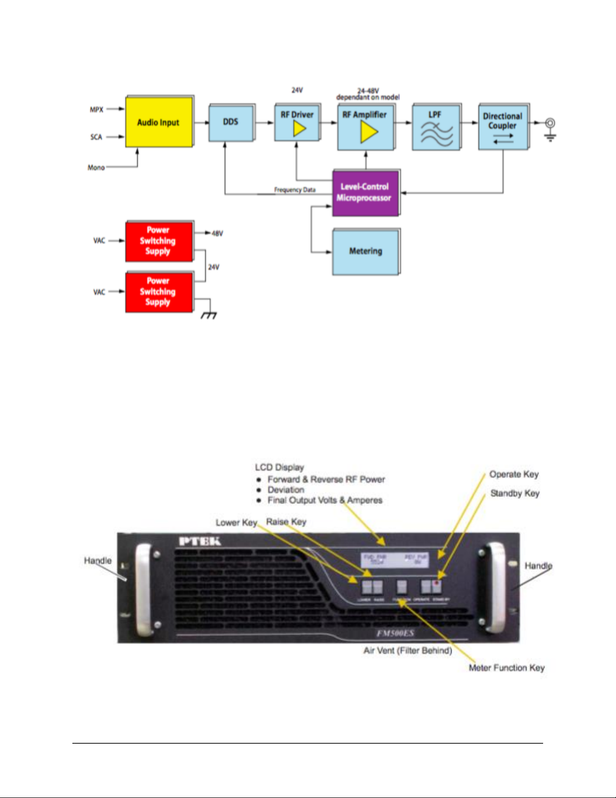
10
Figure 1-2. ES Series System Block Diagram
The ES Series is designed within a 3RU-high (5.25”) form-factor that is 13.75”
(34.9 cm) deep (including the front panel and rear protective flanges; the chassis
body itself is 13” deep) and 17” (43.2 cm) wide (19” including the front panel to
fit a standard size rack.
Features on the ES Series front panel are shown in Figure 1-3.
Figure 1-3. ES Series Front Panel

PTEK April 2016
11
Figure 1-4. ES Series Open Top View (A) and Rear Panel (B)

PTEK April 2016
12
1.2 Specifications
1.2.1 General
Table 1-1 lists general specifications for the ES Series.
Table 1-1. ES Series General Specifications
Parameter
Description
Dimensions
5.25” (3RU) high
17” (43.2 cm) wide (19” including front panel)
13.75” (34.9 cm) deep (including the front panel and rear
protective flanges; the chassis body itself is 13” deep)
Weight
Total shipping weight is 25 pounds
19” Rack-Mountable
with Slide capability
Left and right rack-mount tabs and handles are attached
directly to the chassis.
Temperature
Operating:
Non-Operating:
0°C to +30°C (32°F to 86°F)
0°C to 50°C (32°F to 122°F)
Relative Humidity
Operating:
Non-Operating:
8% to 90% non-condensing
5% to 95% non-condensing
Maximum Wet Bulb
Operating:
Non-Operating:
27°C, non-condensing
35°C, non-condensing
Altitude
Operating:
Non-Operating:
0 to 10,000 feet above sea level
0 to 40,000 feet above sea level

PTEK April 2016
13
1.2.2 Electrical
Table 1-2 lists the electrical specifications for the ES Series.
Table 1-2. ES Series Electrical Specifications
Parameter
Description
Frequency Range
87.7 MHz to 108 MHz
Audio Input Impedance
600 ohms
Audio Input Level (Composite)
1.25 volts RMS
Audio Input Level R & L Stereo Encoder
(optional)
Frequency Response (Composite)
20 Hz to 15 (90) KHz
Pre-Emphasis
75 (or 50 uS to order)
Harmonic Distortion
less than 0.1%
Signal-to-Noise Ratio
>70 dB rms
RF Output Impedance
50 ohms
Output Connector
N-type female
RF Power Output
1050W, 500W, 300W
Harmonic Attenuation
Meets or exceeds FCC requirements
Power Requirements
88-264 VAC, internally fused
Fuse
MDA 10 Amperes, 250 Volts AC
1.2.2.1 System Power
The ES Series FM500 uses three AC power supplies, and the FM300 uses two.
Each AC power supply is auto-ranging, single-phase AC input from 88 to 264
VAC (47 to 63 Hertz).

PTEK April 2016
14
1.2.2.2 Noise Level
Typical noise levels emitted by the ES Series are outlined in Table 1-3. The
chassis is installed with two 120-mm fans mounted side-by-side at the rear of the
system. In addition, each AC power supply has its own cooling fan.
Table 1-3. Typical Noise Levels of the ES Series
Measured at:
1 Meter
2 Meters
Front
66.24 dB
57.57 dB
Rear
61.53 dB
57.93 dB
1.3 Packaging and Shipping
The ES Series PTEK Transmitter is packaged in a reusable shipping container.
Approximate weight of an empty container and one (1) AC power cord is 9
pounds (4 kg).
The approximate weight of an ES Series (installed with two power supplies) is
under 15 pounds (6.8 kg).
The approximate weight of a manual and associated shipping paperwork is one
(1) pound (0.5 kg).
Therefore, both the shipping container and a fully installed ES Series including
power cord, manual, and associated paperwork weigh under 25 pounds (11.3 kg).

PTEK April 2016
15
Chapter 2
Installation
2.1 Installation Procedures
Caution: Use industry-standard ESD grounding techniques when handling
all components. Wear an antistatic wrist strap and use an ESD-protected
mat. Store ESD-sensitive components in antistatic bags before placing
them on any surface. Handle all IC cards by the front panel or edges only.
There are no operator serviceable parts inside the ES Series; therefore,
replacement, inspection, or adjustment of internal components within the
ES Series requires service by an authorized PTEK technician only. DO
NOT REMOVE THE TOP PROTECTIVE COVER OF THE ES Series
CHASSIS (see following warning).
Warning: Removal of the top protective cover of the ES Series by anyone
other than an authorized PTEK technician will void the product warranty.
Installation
Section

PTEK April 2016
16
2.2 Removing the Protective Top Cover
Warning: Make sure that the AC power cord is removed from the AC
input connector on the rear of the ES Series before removing the
protective top cover.
Open the ES Series Transmitter as follows:
1. Remove the protective top cover of the ES Series by loosening the
two Phillips screws on each side of the chassis (see Figure 2-1).
Figure 2-1. ES Series Right-Side Top Cover Phillips Screws
2. Store the cover and screws in a safe place until replaced.
2.3 Changing the Fuse
The ES Series PTEK Transmitter contains fuses mounted internally in the power
supplies. Changing these fuses is not a normal service item and should only be
necessary if a fault develops in the power supply.

PTEK April 2016
17
2.4 Cleaning the Air Filter
Accessing the air filter requires removing the front panel of the ES Series.
1. Remove the four Phillips screws on the ES Series front panel (see
Figure 2-2).
Figure 2-2. Remove the Front Panel Screws to Access the Air Filter
2. Remove the air filter (see Figure 2-3), then carefully wash it with
mild soap and water.
Figure 2-3. Remove the Exposed Air Filter
3. Check that the exposed air vent holes are unobstructed.
Figure 2-4. Make sure the Air Vent holes are unobstructed
4. After the air filter has been dried, replace it and the front panel.
Make sure the front panel screws are fully tightened.

PTEK April 2016
18
2.5 Rack Mounts
Rack-mount tabs (or flanges) are built into the chassis and therefore are not
removable. They are used to secure the ES Series chassis to a 19” rack.
Rack-mount slides are used to pull the ES Series away from the rack for easier
access.
2.5.1 Mounting Brackets
Use the following steps to ensure an ES Series chassis to a 19” rack.
1. With the help of a second person, carefully insert the ES Series chassis
into the 19” rack (see figure 2-5).
Figure 2-5. Left and Right Rack-Mount Brackets
2. Using four 10-32 screws with corresponding lock washers and nuts, attach
the ES Series chassis to the 19” rack through the four mounting holes of
the mounting brackets.
Caution: Make sure to tighten each mounting screw to assure that the ES
Series chassis is firmly installed onto the 19” rack.


PTEK April 2016
20
Chapter 3
Operation
This chapter describes:
How to set up the ES Series system to begin operation
How to turn the system on and off
How to monitor and change the operational settings of the system
3.1 Set Up the System
To successfully operate the ES Series PTEK Transmitter, an antenna (or power
amplifier) and an audio source must first be connected to the system, as outlined
in the following steps:
1. Connect the antenna or power amplifier input to the RF output connector
on the rear panel of the ES Series (see Figure 3-1).
2. Connect the audio input to one of the following connectors on the rear
panel:
Composite Input (ensure the Stereo encoder is disabled)
Balanced Mono Input
Balanced Stereo Left and Right (if equipped with stereo
encoder)
Operation
Section
This manual suits for next models
3
Table of contents
Other Ptek Transmitter manuals


