Ptek FM150ES Guide

PTEK
111 N. Vista Rd. Ste 3E
Spokane Valley, WA 99212
(509) 290-6652
Website: ptekpower.com
PTEK LLC reseves the right to revise and change any and
all information included in this document.
FM150ES
Operating Manual
and User Guide
Version 1.1— May 2009

Copyright © 2009 PTEK LLC
ALL RIGHTS RESERVED. No part of this publication may be reproduced in any form, by
photocopy, microfilm, retrieval system, or by any other means now known or hereafter invented without
the prior written permission of PTEK LLC.
The information in this publication has been carefully checked and is believed to be accurate. However,
PTEK assumes no responsibility for inaccuracies. PTEK LLC retains the right to make changes to this
publication at any time without prior notice. PTEK does not assume any liability arising from the
application or use of this publication or the product(s) described herein.
RESTRICTED RIGHTS LEGEND:Use, duplication, or disclosure by the United States Government
is subject to the restrictions set forth in DFARS 252.227-7013 (c)(1)(ii) and FAR 52.227-19.
TRADEMARKS and SERVICEMARKS
PTEK®is a registered trademark of PTEK LLC (Limited Liability Corporation).
All other trademarks, servicemarks, or registered trademarks used in this publication are the property of
their respective owners.
FM150ES Operating Manual and User Guide, Version 1.0
March 2009
Part Number: 100101-001
PTEK Customer Support

iii
PTEK Corporation
FM150ES Operating Manual and User Guide
Revision History
Version 1.0......................................................................................... March 2009
Version 1.1......................................................................... ................... July 2009

iv PTEK Corporation
FM150ES Operating Manual and User Guide
Limited Warranty
PTEK LLC (SELLER) warrants that products are free from defects in material and workmanship and meet the
performance specifications stated; however:
A. SELLER liability under this Warranty is limited to repairing or replacing, at its option, any product
delivered not conforming to this Warranty;
B. This Warranty is limited to a period of three years;
C. Minor deviations from specifications that do not affect performance are excluded from this Warranty;
and
D. SELLER shall be liable under this Warranty only if:
1. SELLER is promptly notified in writing by the BUYER upon discovery of the failure of any
product to conform to this Warranty,
2. The product is returned to the SELLER, with transportation charges prepaid by the BUYER,
3. The Product is received by SELLER not later than ten (10) days after the last day of the two-
year period of this Warranty, and
4. SELLER examination of the product discloses the SELLER’s reasonable satisfaction that
such defects or failures as may exist have not been caused by misuse, neglect, improper in-
stallation, repair, alteration, accident, or shipping.
The BUYER will repay freight to and from SELLER on products serviced here under at SELLER’s plant; but
SELLER may, at its option, elect to perform any repairs here under at the BUYER’s place of business.
The foregoing constitutes SELLER’s entire Warranty expressed, implied, and/or statutory, except as to title, and
state the full extent of SELLER’s liability to the BUYER or to any other party for any breach of such Warranty
and for damages, whether direct, special, incidental, or consequential; and other than as expressly provided in
this document. No Warranties, expressed or implied, including any Warranty or merchant ability or of fitness for
a particular purpose, are made. No employee, representative, or agent of SELLER has any authority, expressed or
implied, to alter or to supplement the terms of this Warranty.
Warranty Service
The Limited Warranty covers parts and labor to the original purchaser for three years. Damage caused by misuse
or shipping is excluded from the Warranty.
PTEK
Customer Service Manager
1723 Little Orchard Street—Unit D
San Jose, CA 95125
(408) 448-3342
v
PTEK Corporation
FM150ES Operating Manual and User Guide
Safety Instructions
Safety Instructions
To maximize user safety and ensure correct device operation, all instructions con-
tained in this section should be read carefully.
Before Applying Power
Verify that the line voltage is 115VAC.
Ground the Exciter
To minimize shock hazard, the exciter chassis must be connected to an electrical
ground, the exciter must be connected to the AC power mains through a three-con-
ductor power cable, with the third wire connected to an electrical ground (safety
ground) at the power outlet. Any interruption of the protective (grounding) con-
ductor or disconnection of the protective earth terminal will cause a potential
shock hazard that could result in personal injury. If the exciter is to be energized by
any other source be certain that the chassis is connected to a separate safety
ground.
Caution: It is important that the user observe all warnings and instructions that
are on the device and contained in this manual.
Warning: DO NOT OPERATE IN AN EXPLOSIVE ATMOSPHERE
Operation of the FM150ES in the presence of flammable gasses or fumes can
endanger persons proximate to the site of operation.
Caution: NO NOT REMOVE THE EXCITER COVER
Removal of the exciter cover will invalidate the FM150ES Warranty. Compo-
nent replacement and internal adjustments must be made only by PTEK quali-
fied service personnel.
vi PTEK Corporation
FM150ES Operating Manual and User Guide
Fuses
Only fuses with the same required current, voltage rating, and specified type (nor-
mal blow, time delay, etc.) should be used. Do not use repaired fuses or short-cir-
cuited fuseholders. To do so could cause a shock or fire hazard.
Output Connector
Electrostatic Discharge (ESD)
A sudden discharge of electrostatic electricity can destroy static-sensitive devices
or micro-circuitry. Proper packaging and grounding techniques are necessary pre-
cautions to prevent damage. Always take industry-standard precautions.
Grounding Methods
Guard against electrostatic damage at workstations by following these steps:
1. Cover workstations with approved anti-static material. Provide a wrist strap connect-
ed to a work surface and properly grounded tools and equipment.
2. Use anti-static mats, heel straps, or air ionizers to give added protection.
3. Handle electrostatic-sensitive components, boards, and assemblies by the case or the
PCB edge.
4. Avoid contact with pins, leads, or circuitry.
5. Turn off power and input signals before inserting and removing connectors or test
equipment.
6. Keep the work area free of non-conductive materials such as ordinary plastic assem-
bly aids and Styrofoam.
7. Use field service tools, such as cutters, screwdrivers, and vacuums that are conduc-
tive.
Warning: The type-N output connector carries dangerously high RF voltages
that present shock and burn hazards. Never operate the FM150ES exciter with-
out properly terminating the output connector in either an adequately rated load
or antenna.

vii
PTEK Corporation
FM150ES Operating Manual and User Guide
Safety Instructions
General Safety Rules
• The device must be used in accordance with the instructions for use.
• Electrical installations in the room must correspond to the requirements of respective regu-
lations.
• Take care that there are no cables, particularly mains cables, in areas where persons can trip
over them.
• Do not use a mains connection in sockets shared by a number of other power consumers. Do
not use an extension cable.
• Only use the mains cable supplied.
• The unit is completely disconnected from the power source only when the power cord is dis-
connected from the power source. Therefore the power cord and its connectors must always
remain easily accessible.
• Do not set up the device in the proximity of heat sources or in a damp location. Make sure
the device has adequate ventilation.
• All plugs on the connection cables must be screwed or locked to the chassis housing.
• The device is designed to be used in horizontal position only.
• The device is no longer safe to operate when the device has visible damage or the device no
longer functions.
• In case of system malfunction or visible damage to the FM150ES, the device must be shut
down and secured against unintentional operation.
• Repairs may only be carried out by a person authorized by PTEK LLC.
• If extensions are made to the FM150ES, the legal stipulations and the device specifications
must be observed.
• The FM150ES must be switched off when removing the top cover.

viii PTEK Corporation
FM150ES Operating Manual and User Guide

ix
PTEK LLC
Table of Contents
Limited Warranty ................................................................................................................. iv
Warranty Service .................................................................................................................. iv
Safety Instructions...................................................................................................................v
Preface................................................................................................................................... xiii
Website Information ........................................................................................................... xiv
Your Comments are Welcome ............................................................................................ xiv
Notes, Cautions, Warnings, and Sidebars ...........................................................................xv
1. Overview and Specifications ........................................................................................ 1-1
1.1 Overview ................................................................................................................ 1-1
1.2 Specifications ......................................................................................................... 1-4
1.2.1 General ....................................................................................................... 1-4
1.2.2 Electrical .................................................................................................... 1-5
1.2.2.1 System Power ............................................................................. 1-5
1.2.3 Environmental ............................................................................................ 1-6
1.2.3.1 Shock .......................................................................................... 1-6
1.2.3.2 Electrostatic Discharge ............................................................... 1-6
1.2.3.3 Noise Level ................................................................................. 1-6
1.3 Packaging and Shipping ......................................................................................... 1-7
1.3.1 Rack-Mount Slides (Optional) ................................................................... 1-7
2. Installation ..................................................................................................................... 2-1
2.1 Installation Procedures ........................................................................................... 2-1
2.2 Removing the Protective Top Cover ..................................................................... 2-2
2.3 Removing a Power Supply .................................................................................... 2-2
2.4 Changing the Fuse ................................................................................................. 2-5
2.5 Cleaning the Air Filter ........................................................................................... 2-6

xPTEK LLC
FM150ES Operating Manual and User Guide
2.6 Rack Mounts .......................................................................................................... 2-7
2.6.1 Mounting Brackets ..................................................................................... 2-7
2.6.2 Rack-Mount Slides (Optional) ................................................................... 2-8
3. Operation ....................................................................................................................... 3-1
3.1 Set Up the System .................................................................................................. 3-1
3.2 Power Up the System ............................................................................................. 3-2
3.3 Getting Started ....................................................................................................... 3-4
3.3.1 Startup Sequence ........................................................................................ 3-4
3.3.2 Changing the Stereo Encoder .................................................................... 3-5
3.3.3 Audio ......................................................................................................... 3-6
3.3.4 Final Check ................................................................................................ 3-7
3.4 Additional Adjustments ......................................................................................... 3-9
3.5 Tune Up the Antenna ........................................................................................... 3-10
3.6 Power Down the System ...................................................................................... 3-11
Appendix A. Connector Pinouts ...................................................................................... A-1
A.1 Accessory Port ...................................................................................................... A-1
Appendix B. Rack-Mount Slide Installation ...................................................................B-1
Index ................................................................................................................Index-1
Reader Comment Card

xi
PTEK LLC
FM150ES Operating Manual and User Guide
Table of Contents
List of Figures
Figure 1-1 FM150ES FM Stereo Broadcast Transmitter .................................................. 1-1
Figure 1-2 FM150ES System Block Diagram................................................................... 1-2
Figure 1-3 FM150ES Front Panel ..................................................................................... 1-2
Figure 1-4 FM150ES Open Top View (A) and Rear Panel (B)........................................ 1-3
Figure 2-1 FM150ES Right-Side Top Cover Phillips Screws........................................... 2-2
Figure 2-2 Remove the Four Phillips Screws from the
Power Supply Mounting Plate 2-3
Figure 2-3 Disconnect Five Wires before Removing Power Supplies.............................. 2-4
Figure 2-4 Remove Fuse Holder to Remove Fuse ............................................................ 2-5
Figure 2-5 Remove the Front Panel Screws to Access the Air Filter................................ 2-6
Figure 2-6 Remove the Exposed Air Filter ....................................................................... 2-6
Figure 2-7 Make Sure the Air Vent Holes are Unobstructed ............................................ 2-6
Figure 2-8 Left and Right Rack-Mount Brackets.............................................................. 2-7
Figure 3-1 FM150ES Rear-Panel Connectors................................................................... 3-2
Figure 3-2 Plug the Power Cord into the FM150ES AC Power Socket............................ 3-3
Figure 3-3 After Power has been Applied to the FM150ES, it enters Standby mode....... 3-3
Figure 3-4 After the OPERATE Key is Pressed, the Startup Sequence Begins................ 3-4
Figure 3-5 Stereo Encoder Can be Changed Through the LCD Display .......................... 3-5
Figure 3-6 Press the RAISE or LOWER key to Change the LCD Display....................... 3-5
Figure 3-7 The Deviation Screen is Displayed through the FUNCTION Key ................. 3-6
Figure 3-8 Audio Gain Can be Adjusted Through the LCD Display................................ 3-6
Figure 3-9 Press the FUNCTION Key to read Frequency ................................................ 3-7
Figure 3-10 Press the FUNCTION Key to read Audio Gain .............................................. 3-7
Figure 3-11 Press the FUNCTION Key to read VOLTS & AMPS .................................... 3-8
Figure 3-12 Press the FUNCTION Key to read Forward & Reverse Power ...................... 3-8
Figure 3-13 Press the FUNCTION Key to read Deviation ................................................. 3-8
Figure 3-14 Press LOWER/RAISE/FUNCTION Keys Simultaneously............................. 3-9

xii PTEK LLC
FM150ES Operating Manual and User Guide
Figure 3-15 TO COME........................................................................................................ 3-9
Figure 3-16 TO COME...................................................................................................... 3-10
Figure 3-17 TO COME...................................................................................................... 3-10
Figure A-1 Accessory Port Pinout..................................................................................... A-1
Figure B-1 FM150ES Right-Side Rack-Mount Slide Holes.............................................. B-2
Figure B-1 FM150ES FM Stereo Broadcast Transmitter
Rack-Mount Slide Installation B-3
Figure B-2 CLB-203 Rack-Mount Slide with Quick Disconnect...................................... B-4
List of Tables
Table 1-1 FM150ES General Specifications................................................................... 1-4
Table 1-2 FM150ES Electrical Specifications................................................................ 1-5
Table 1-3 Typical Noise Levels of the FM150ES........................................................... 1-6
Table A-1 Accessory Port Pinout Signal Descriptions ................................................... A-2

xiii
PTEK LLC
Preface
This document, entitled FM150ES Operating Manual and User Guide, provides
instructions on how to install, configure, power up, and perform diagnostics on the
150-watt PTEK FM150ES FM Stereo Broadcast Transmitter (see photo below), an
easy-to-use and versatile system that can be used in either stand-alone or backup
mode. The information contained within is intended for an experienced system oper-
ator with a knowledge of high-performance broadcast transmission systems.
The 2RU-high (3.5”) FM150ES is designed to fit a standard 19” rack and is provided
with rack-mount left and right brackets and handles. Optional rack-mount slides are
also available. The FM150ES is rugged enough to withstand extreme shock (up to
5G), temperature (up to 50°C), and EMI such as that associated with broadcasting
from remote rugged environments.
FM150ES FM Stereo Broadcast Transmitter

xiv PTEK LLC
FM150ES Operating Manual and User Guide
Key features of the FM150ES FM Stereo Broadcast Transmitter include:
• Totally solid-state no-tune construction
• Wide input range from 88 to 264 VAC
• 3-year warranty on all parts and labor
• Built-in field-programmable FSK ID for translator use
• Remote-control interface
•Optional built-in stereo encoder
• Rugged design withstands up to 5G forces and 50°C
• Meets or exceeds all FCC and CCIR standards
• Designed and manufactured in the United States
The FM150ES is FCC-certified for use on LPFM stations. Frequency stability for
each unit is ensured by using PLL (phase-locked loop) frequency synthesis from a
highly stable crystal oscillator. All units incorporate over-temperature protection and
VSWR foldback to automatically reduce power output to safe operating levels.
Switch-mode power supplies provide consistent performance even when there are
frequent power outages and voltage fluctuations that make stressful demands on
power dependence.
An overview and specifications of the FM150ES FM Stereo Broadcast Transmitter
is given in Chapter 1, "Overview and Specifications", of this manual.
Website Information
PTEK corporate and product information may be accessed on the World Wide Web
by browsing the website http://www.ptekpower.com.
Your Comments are Welcome
We are interested in improving our documentation and welcome your comments and
suggestions. You can email your comments to us at docfeedback@ptekpower.com.
Please include the document part number in the subject line of your email.
Preface
Notes, Cautions, Warnings, and Sidebars
xv
PTEK LLC
Notes, Cautions, Warnings, and Sidebars
The following icons and formatted text are included in this document for the reasons
described:
Note: A note provides additional information concerning the procedure or action
being described.
Caution: A caution describes a procedure or action that may result in injury to the op-
erator or equipment. This may involve—but is not restricted to—heavy equipment or
sharp objects. To reduce the risk, follow the instructions accompanying this symbol.
Warning: A warning describes a procedure or action that may cause injury to the
operator or equipment as a result of hazardous voltages. To reduce the risk of elec-
trical shock and danger, follow the instructions accompanying this symbol.
Sidebar: A “sidebar” adds detail to the section within which it is placed,
but is not absolutely vital to the description or procedure of the section.

xvi PTEK LLC
FM150ES Operating Manual and User Guide
1-1
PTEK LLC
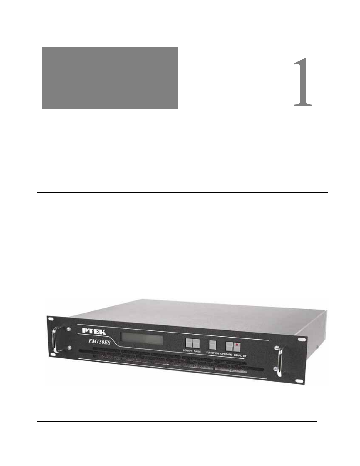
1FM150ES FM Stereo Broadcast Transmitter
Overview and Specifications
1.1 Overview
The 2RU-high (3.5”) FM150ES FM Stereo Broadcast Transmitter is designed to
fit a standard 19” rack and is provided with rack-mount left and right brackets and
handles. Optional rack-mount slides are also available. The FM150ES is rugged
enough to withstand extreme shock (up to 5G), temperature (up to 50°C), and EMI
such as that associated with broadcasting from remote rugged environments. (see
Figure 1-1; a block diagram is given in Figure 1-2, page 1-2). The FM150ES sup-
ports Mono, Wideband Stereo (left and right) and SCA inputs, ideal for a variety of
commercial and dedicated stereo broadcast transmission applications.
Figure 1-1. FM150ES FM Stereo Broadcast Transmitter
General
Section Chapter

FM150ES Operating Manual and User Guide
1-2 PTEK LLC
The FM150ES is designed within a 2RU-high (3.5”) form-factor that is 13.75” (34.9
cm) deep (including the front panel and rear protective flanges; the chassis body itself
is 13” deep) and 17” (43.2 cm) wide (19” including the front panel to fit a standard-
size rack).
Features on the FM150ES front panel are shown in Figure 1-3.
Figure 1-2. FM150ES System Block Diagram
Figure 1-3. FM150ES Front Panel
Audio Input
Power
Switching
Supply
Power
Switching
Supply
MPX
24V
24V
36V
48V
VCO
PLL Frequency Data
SCA
Mono
VAC
VAC
Directional
Coupler
RF Driver RF Amplifier
Level-Control
Microprocessor
Metering
LPF
Air Vent (Filter Behind)
Standby Key
Operate Key
Handle
Meter Function Key
Lower Key
Raise Key
LCD Display
Handle
Forward & Reverse RF Power
Deviation
Final Output Volts & Amperes
Overview and Specifications
Overview
1-3
PTEK LLC
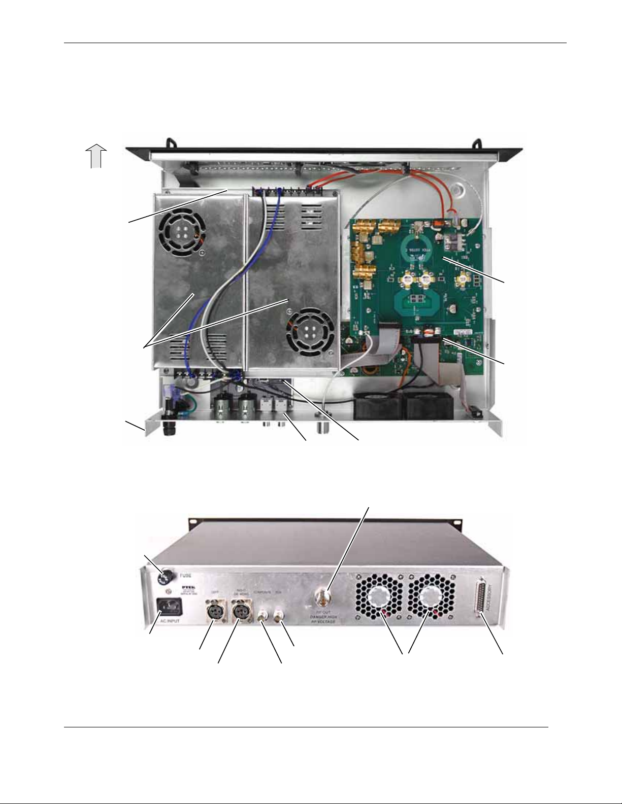
Major internal components of the FM150ES can be seen in the open top view (cover
removed) displayed in Figure 1-4 (A). Features on the FM150ES rear panel are
shown in Figure 1-4 (B).
Figure 1-4. FM150ES Open Top View (A) and Rear Panel (B)
AC Power Supplies (2)
AFM150ES Top View (Cover Off)
BFM150ES Rear Panel
Accessory PortDual Cooling Fans
RF Output
Fuse (10A)
AC Input
Balanced Audio (Left Stereo Input)
Balanced Audio (Right Stereo or Mono)
SCA Input
Rear Protective Flange
(1 of 2)
Front
Composite Input
Frequency Generation
& Audio Processing
High power amplifier
and Harmonic Filter
Control and
Metering Board
Control Board
Exciter Board
(underneath Power Supplies)

1-4 PTEK LLC
FM150ES Operating Manual and User Guide
1.2 Specifications
1.2.1 General
Table 1-1 lists general specifications for the FM150ES.
Table 1-1. FM150ES General Specifications
Parameter Description
Dimensions z3.5” (2RU) high
z17” (43.2 cm) wide (19” including the front panel)
z13.75” (34.9 cm) deep (including the front panel and rear protective flanges;
the chassis body itself is 13” deep)
Weight Total shipping weight is under 33.5 pounds (15.2 kg) and includes the following:
zChassis = under 24 pounds (10.9 kg), including two AC power supplies
zAdd 8.5 pounds (4 kg) for the shipping container and one AC power cord
zThe manual and associated shipping paperwork weigh approximately 1 lb
(0.5 kg)
19” Rack-Mountable
with Slide capability zLeft and right rack-mount tabs and handles are attached directly to the chas-
sis. Rack-mount slides are optional.
Temperature
Operating:
Non-Operating: z0°C to +50°C
z–40°C to +70°C
Relative Humidity
Operating:
Non-Operating: z8% to 90% non-condensing
z5% to 95% non-condensing
Maximum Wet Bulb
Operating:
Non-Operating: z27°C, non-condensing
z35°C, non-condensing
Altitude
Operating:
Non-Operating z0 to 10,000 feet above sea level
z0 to 40,000 feet above sea level
Table of contents
Other Ptek Transmitter manuals


