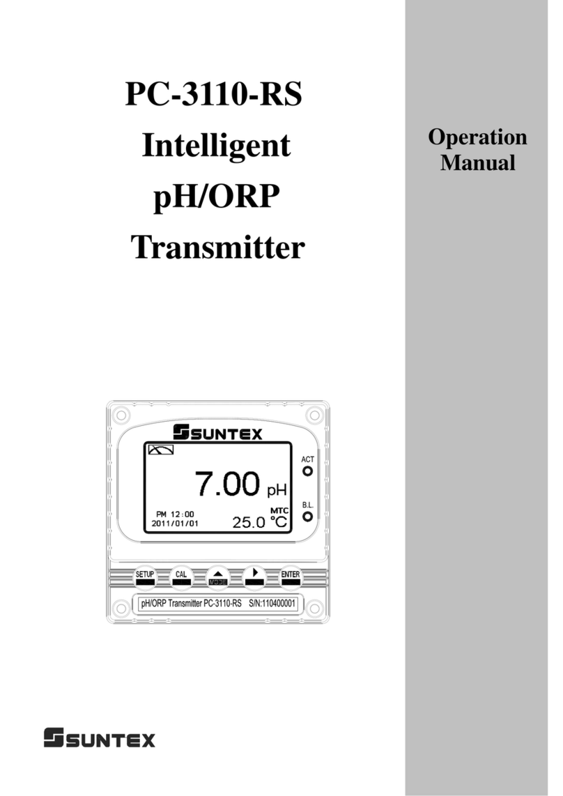
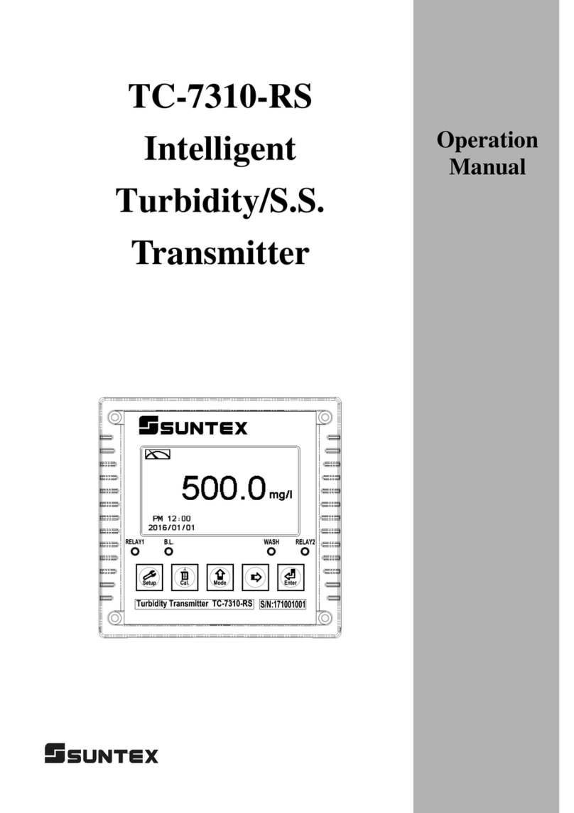
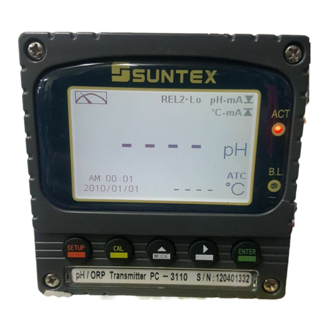
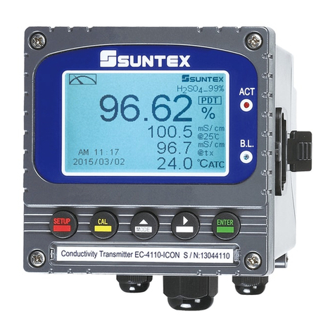
Suntex CT-6110-POL User manual

1
CT-6110-POL
Intelligent
Residual Chlorine
Transmitter
Operation
Manual

Precautions for installation
Brief Instruction 1
1. Specifications
1.1 Specifications 4
1.2 Product model and spare part order number 6
1.3 Measurement principle 7
2. Assembly and installation
2.1 Illustration of overall structure 8
2.2 Installation dimensions and combinations 10
2.3 Illustration of flow configuration 12
3. Overview of Residual Chlorine Transmitter CT-6110-POL
3.1 Illustration of rear panel 14
3.2 Illustration of terminal function 14
3.3 Description of terminal function 15
3.4 Illustration of electrical connection 16
4. Configuration
4.1 Illustration of front panel 17
4.2 Keypad 17
4.3 LED indicators 17
5. Operation
5.1 Measurement mode 18
5.2 Set-up menu 18
5.3 Calibration menu 18
5.4 Shortcuts 18
5.5 Default value
5.5.1 Setting default value 18
5.5.2 Calibration default value 19
6. Measurement display mode
6.1 Text mode 20
6.2 Real-time chart mode 21
6.3 Trace mode 22
6.4 Warning symbols and text 23
7. Settings
Block diagram of settings 24
7.1 Entry of set-up menu 26
CONTENTS

7.2 Security code of settings(Code) 27
7.3 Language 28
7.4 Mode(Display type) 29
7.5 Span Adjustment 30
7.6 Polar. Volt 31
7.7 Polarogram 32
7.8 pH function 33
7.9 Temperature 34
7.10 Motor 35
7.11 Relay 1 36
7.12 Relay 2 38
7.13 Clean/Auto Zero 40
7.14 Analog output 41
7.15 Date/Time (Clock) 43
7.16 RS-485 communication 44
7.17 Sample average of measurements (Digital filter) 45
7.18 Backlight settings 46
7.19 Contrast settings 47
7.20 Logbook 48
7.21 Automatically back to measurement mode(Return) 49
8. Calibration
Block diagram of Calibration 50
8.1 Entry of calibration menu 51
8.2 Security password of calibration 52
8.3 Free Cl2 calibration 53
8.3.1 Zero point calibration 53
8.3.2 Span calibration 54
8.4 pH Calibration 55
8.5 Motor 59
8.6 Automatically back to measurement mode(Return) 60
9. Modbus protocol and instructions 61
10. Maintenance 67
11. Error messages (Error code) 70
12. Appendix 72

Thank you for purchasing Suntex products. In order to continually improve and enhance the transmitter’s
function, Suntex reserves the right to modify the content and icon display of the product. The actual situation
is subject to the instrument without notice. The operation manual is only provided for function and
installation description, Suntex Instruments Co., Ltd. is not liable for any person or entity for any direct or
indirect loss or damage due to improper usage of this product. If you have any questions or find omission,
negligence or mistakes of the operation manual, please contact with our staff, thank you.
Precautionsforinstallation
Wrong wiring will lead to breakdown or electrical shock of the instrument, please read this
operation manual clearly before installation.
Make sure to remove AC power from the transmitter before wiring input, output connections,
and remove it before opening the transmitter’s housing.
The installation site of the transmitter should be good in ventilation and avoid direct
sunshine.
The material of signal cable should be special coaxial cable. Strongly recommend using our
coaxial cable. Do not use normal wires instead.
Avoid electrical surge when using power. Especially when using three-phase power, use
ground wire correctly. If the power surges interference occurs, separate the power supply of
transmitter from the control device, such as: dosing machines, mixers, etc. to make individual
power supply for the transmitter; or set surge absorber to reduce the power surges at all
electromagnetic switches and power control device coils.
The internal relay contact of the instruments is for alarm or control function. Due to safety,
please must connect to external relays which can stand enough ampere to make sure the
safety operation of the instrument.(Please refer to chapter 3.4“Illustration of electrical
connection”)
The power voltage and the frequency for the power supply of transmitter are absolutely
necessary to follow the designated power requirement of the order number model to avoid
motor damage.
There a manufacturer logo usually shows in the display of transmitter, and the illustration of
each function in the manual is no longer expressed.

Brief Instruction
Description of set-up settings (see chapter 7 for details)
Press and simultaneously to see the overview of the set-up settings now. Then press I
if you would like to modify set-up settings. Press keypad according to index of keypad on the screen.
Index of keypad
keypad Accordingly item Description
Back to upper layer
Choose leftward of change to left page
Increase digit
Choose rightward of change to right page
Decrease digit
Confirm settings after modifications and then go through next
step
Selection of set-up items
keypad Accordingly item Description
Mode Measurement mode, select from normal(text) mode, real-time
chart mode, trace mode display
Span Adj.
Span adjustment, allow directly measured value alignment from
measurement status
Polar. Volt Polarization voltage setting, to set the initial volt and gain
Polarogram
Apply polarization curve to record relationship between
scanning voltage and current to help set the appropriate volume
of polarization voltage
pH
pH function setting, to activate the pH measurement function
and select pH compensation (for Free Cl2) method
Temperature
Temperature measurement and compensation, including ATC
and MTC mode. MTC---Manual temperature compensation,
ATC--- auto temperature compensation
1

Motor
Motor setting, to activate the motor and water sample level
detection function
Relay 1 First relay setting, to choose action off or Hi/Lo alarm
Relay 2 Second relay setting, to choose action off or Hi/Lo alarm
Cln/Auto Zero
Automatic wash/auto zero time setting, to set clean device or
zero point filtered water device ON and OFF duration
Analog Current output according to Free Cl2or pH setting range
Clock
Clock setting (When out of power and reboot it, the
instrument’s time setting can maintain to the real time. If
not, please replace the inner 3V CR2025 battery.)
RS-485 RS485 serial interface (Modbus protocol)
Black-light Backlight setting, to set Auto/ON/OFF backlight, brightness,
and sensitivity
Contrast Contrast of screen setting
Digital Filter Take every serial 1~60 measurements, average them
continuously, and make it as the readings
Logbook Event recorder logbook (50 data)
Return Setting of returning to the measurement mode
Code
Security code of set-up mode. The set-up code is precedential to
calibration code, thus it can pass a different security code of
calibration.
Language Available for English, Traditional Chinese, Simplified Chinese
2

Description of calibration settings (see chapter 8 for details)
Press and simultaneously to see the last calibration information. Then press if you
would like to make a new calibration or modify setting of calibration. Press keypad according to
index of keypad on the screen.
Index of keypad:
keypad Accordingly item Description
Back to upper layer
Choose leftward of change to left page
Increase digit
Choose rightward of change to right page
Decrease digit
Confirm settings after modifications and then go through next
step
Selection of calibration items
keypad Accordingly item Description
Free Cl2Free Cl2 calibration, select from Zero or Span calibration
pH
pH calibration, select from TECH, NIST, and Any buffer
calibration mode
Motor
Motor setting, to activate the motor and water sample level
detection function
Return Time interval setting of returning to the measurement mode
Code Security code of calibration mode.
Note
Due to the need for continuous improvement of the transmitter function, we reserve the right to modify the
content and the icon of the function. The actual icons and contents are subject to the instrument without notice.
3

1.Specifications
1.1 Specifications
Main specifications:
CT-6110-POL (Non-reagent type free chlorine transmitter)
Measuring mode Residual(Free) Chlorine & pH / Temperature, Simultaneous display
Measuring
range
Free Cl20.00~3.00mg/l (Free Cl2corresponding range adjustable for graphical display)
pH -2.00~16.00pH
Temp 0.0~60.0C
Resolution
Free Cl20.01mg/l
pH 0.01pH
Temp 0.1C
pH compensation/
accuracy pH sensor auto compensation/ manual compensation/ OFF / ±0.01pH(±1 digit)
Temp. compensation/
accuracy NTC-30K(compensation range: 0~45C)/ ±0.2C (±1 digit)
Display Large LCM with sensitization sensor for auto/manual illumination function and
contract function
Display mode
Text mode: Numerical display
Chart mode: 3 mins real-time dynamic graph
(Free Cl2corresponding range adjustable)
Trace mode: Set up from 3 mins to 4 weeks duration of the measured value trend graph
(Free Cl2corresponding range adjustable)
Analog output Isolated DC 0/4~20mA corresponding to Free Cl2or pH, max. load 500
Voltage output DC ± 12V, 1W max. for PH-300T(Optional)
Logbook 50 event records
Serial interface Isolated RS-485(Modbus RTU or ASCII)
Setting Contact 240VAC, 0.5A Max. (recommended)
Activate Two individual Free Cl2or pH, Hi/Lo selectable, limited programmable
Clean/Auto Zero 240VAC, 0.5A Max. (recommended),
ON:0~99 min. 59 sec. OFF:0~999 hours 59 min.
Cl2
calibrati
on
Zero point Electrodeopencircuit
or apply activated charcoal filtered water (residual chlorine free water) / pure water
Span Sampling DPD measurement input calibration or standard buffer calibration
pH calibration Any, Tech & NIST buffer calibration
Diagnostic function Temperature sensor, zero-point & slope diagnosis, water/power outage,
logbook record or alarm symbol
Measurement system
Measuring principle Polarographic (No reagent needed for measurement)
Residual chlorine
electrode
2 in 1 rotating electrode (Working electrode: gold, Counter electrode: silver)
With relative slope index for electrode aging determination
Temperature probe NTC-30K
pH electrode Optional(No need for pH compensation when pH range within pH 6.5~7.5)
Cl2 electrode cleaning Ceramic beads auto cleaning
Motor protection Auto over heat protection
Water outage/
Electrode open
diagnosis
When water outage or electrode open, after auto diagnosis the motor auto shuts down
4

Performance
Repeatability ±2% Full Scale
Linearity ±5% Full Scale
Accuracy ±2% Full Scale
Response time <60 sec for 0~2mg/l, or < 90 sec for 2~3mg/l (90% response time)
Other specifications:
Piping connection size and flow-through chamber(Not including piping couplings)
Flow-through chamber Transparent, acrylic flow-through chamber
Inlet connection 1/4” NPT thread
Outlet connection 1/4” NPT thread
Spare connection 1/4” NPT thread
Sample conditions
Sample temperature 0~50C
Inlet pressure 0.01 ~ 2 kgf/cm2(as not overflow as the criteria)
Inlet flow 0.1~2 L/min (as not overflow as the criteria)
pH range pH 5~9 (Optional pH sensor for auto compensation)
Environment
Ambient temperature 0~50C
Storage temperature -10~70C
Ambient humidity 5~95%RH
Power
Power voltage/
Frequency
01: AC220V(-15~+10%) / 60Hz, 02: AC220V (-15~+10%)/ 50Hz
03: AC110V (-15~+10%)/ 60Hz, 04: AC110V (-15~+10%)/ 50Hz
(Note: Single-phase electric power)
(Designate the power voltage & frequency type when ordering)
Power consumption Approx. 30W
Dimensions
Installation Wall mounting
System dimensions ~316 mm 326 mm 195 mm (HWD)
Weight Approx. 4.5kg
Protection Transmitter: IP 65 (NEMA 4X)
Note: The specifications are subject to change without notice.
5

1.2 Product model and spare part order number
Model Sensor Code Power Code
CT-6110 -POL
POL:Polarographic
-03
01: Single-phase,AC 220V(-15~+10%)/60Hz
02: Single-phase,AC 220V(-15~+10%)/50Hz
03: Single-phase,AC 110V(-15~+10%)/60Hz
04: Single-phase,AC 110V(-15~+10%)/50Hz
Standard accessories:
1. Transmitter
2. Sensor assembly(Including Cl2electrode, temperature probe, motor & driving device)
3. Flow-through chamber
4. Measuring cup
5. Ceramic beads pack x 2
6. Inlet/Outlet couplings
7. Wall mounting frame
8. Transmitter mounting plate
9. Acrylic cover
10. Cable gland (If the original glands are not enough for wiring, the additional cable gland is
available for installation at back cover)
If necessary, please order the spare parts as follows:
1. Free Cl2electrode: 8-CL-01
2. Ceramic beads: 8-40 (Weight about 40g)
3. pH electrode housing(Optional): 8-41
4. pH electrode(Optional): Select a suitable pH sensor. When installation, it is necessary to
move the sensor assembly box to the clean position. Open the box upper cover, and install
the pH electrode housing from the box bottom side up. Let the pH cable go through the pH
cable gland of sensor assembly box. Finally, insert the pH electrode into the pH electrode
housing. Please make sure that the pH electrode does exceed the tip of housing.(If the outer
diameter of pH electrode head is too small, the electrode may exceed the tip of the housing.
If so, it is suggested to apply O-ring at the bottom side of pH electrode head.) It will prevent
the pH electrode from damaging by the bottom of the flow-through chamber.
5. pH buffers (Optional)
6

1.3 Measurement principle
The instrument applies polarogram principle to detect the free available chlorine which include
chlorine(C12) , hypochlorous acid(HOCl) and hypochlorite ion(OCl-) in the water.
Cl2 + H20 ↔HOCl + H+ + Cl-
HOCl ↔H+ + OCl-
The CT-6110-POL utilizes the motor and timing belt to rotate the free chlorine sensor which
dips into fresh water flow, and provides bias voltage between the working electrode(gold
electrode) and the counter electrode(silver electrode) of the free chlorine sensor. Thus, the
electrode will react to free chlorine in the water , and it results in an oxidation-reduction
reaction(redox) and generates diffusion current. By measuring the current and combining the
temperature measurement, the concentration of free chlorine in the water is determined.
There is a default setting for pre-set initial volt and volt adjustment gain. Normally, the
pre-set initial volt and gain is applied for water sample measurement. When the concentration
has changed, the instrument is able to search for the most suitable measurement volt to result in
new concentration value. If the sample water is necessary to change the initial volt and gain, the
polarogram function can be utilized to set the polarogram volt. (For diagram of scan
volt/current, please refer to ch7.7 Polarogram.) Select the voltage of stable current range(which
means voltage change but little change in current range), and then set the voltage as initial volt
in the transmitter’s polar. volt setting (Please refer to ch7.6 Polar. Volt.).
In most cases, it only needs to apply the pre-set initial volt and gain, and it is not necessary to
proceed the polarogram scanning function as the previous description. When measurement
under different conductivity range water sample, it will be necessary to set a suitable gain to
prevent measurement error.(Please refer to ch7.6 Polar. Volt.)
While the free Cl2electrode is rotating, in order to maintain the measurement accuracy, it also
applies ceramic beads to clean the electrode suffice simultaneously. For the first operation or for
long stop duration of the motor, please let the electrode continuously operate at least one hour
and then start the measurement work. The electrode is a consumable part, and it is necessary to
be replaced after a period of use. Users may set the electrode at 100% relative slope while
calibration(such as at the first calibration of the electrode). Then the relative slope value will
show after every calibration is done. Apply the value for the determination index of electrode
aging condition.
Temperature changes can affect the measured value of residual chlorine concentration. The
instrument can apply the temperature value which is measured by a temperature probe for
making a temperature compensation for residual chlorine concentration.
Changes in pH also affect the measured value of residual chlorine concentration. The
standard measurement range for sample solution is pH 6.5~7.5. If the pH value of the sample
solution exceeds the range, it is suggested to apply a pH electrode(optional), the instrument will
automatically make a pH compensation for residual chlorine concentration.
7

2. Assembly and installation
2.1 Illustration of overall structure
Motor AC power cord
pH electrode(Optional)
Temperature probe
Rotary joint
Flow-through chamber
Motor
Transmitter
Acrylic cover
Transmitter mounting plate
Inlet
Temperature probe
Cl2electrode
pH electrode housing
(Optional, when installation, please
screw it from measuring box bottom
side up. The pH electrode cannot exceed
the tip of housing.)
Motor start capacitor
Motor drive belt
Pulley
Transmitter clip holder
Star knob
(The transmitter is
mounted under the support
plate. When operation, first
unscrew the knob and open
the acrylic cover plate.
The plastic screws inside the
holes are for fixing while
delivery. It does not affect
the measurement whether
disassembly or not. For the
convenience of moving the
flow-through chamber for
cleaning, users may decide to
disassembly them or not.
Wall mounting frame
Cl2sensor cable
Temp. probe cable
pH electrode cable (Optional)
Spare
Connected to the transmitter terminal block
Motor H type
terminal blocks
Reducer
Measuring cup
pH electrode
(Optional, when
installation, please
refer to ch2.2.1 and
move the sensor box
to the support plate
cleaning position.)
pH electrode housing
(Optional)
Ceramic beads
(One pack of ceramic
beads should be put into
measuring cup. Ceramic
beats height cannot
reach the silver
electrode. The other
pack is for the backup.)
Bearing with housing
Ball valve
Sealing plug (Please
remove it before
piping or sampling.)
Screw of transmitter fixing plate
(When wiring, the screws can be
unscrewed , and use the left
screw as a fulcrum, unscrew it a
bit, swing the transmitter with the
fixing plate until the transmitter
back side is outward to help for
the convenience of wiring.)
Sensor box
Cable gland
Cl2electrode and
temperature probe
6pin terminal blocks
Rotary joint
8

Wiring of residual chlorine electrode and temperature probe:
Sensor box Transmitter
Cl2sensor
wiring
Lower level of 6PIN
terminal block for Cl2sensor
and temperature probe
Upper level of 6PIN terminal
block for signal cable to
transmitter’s terminal block
Rear terminal
block
Lower end of
rotary joint ○
1Brown(Thick wire) ○
1Brown (11) CE (silver)
Upper end of
rotary joint ○
2Red(Thick wire) ○
2Red (12) WE(gold)
Temperature
probe
○
3Black ○
3Black (15) SG
○
4Red ○
4Yellow (16) T/P
○
5Green ○
5Orange (17) SG
Installation of cable gland:
If the original glands are not enough for wiring, the additional cable gland is available for
installation.
1. Remove the waterproof plug(A) from the back cover.
2. Set the rubber gasket(C) in the cable gland (B), and screw into the back cover.
3. Use a fixing nut(D) from the inside of the back cover to fix up the cable gland(B).
○
6○
5○
4○
3○
2○
1
○
6○
5○
4○
3○
2○
1
9

2.2 Installation dimensions and combinations
2.2.1 Installation dimensions
(Suggested reserved space)
Moving
direction
when
cleaning
(reserved min. space)
10

2.2.2 Combination types
As shown below, the user can decide to configure the transmitter above or below the
support plate.
11

2.3 Illustration of flow configuration
2.3.1 Piping of flow-through chamber
Assemble the couplings according to following illustration
2.3.2 Piping of flow-through chamber(When install with a pH sensor)
When the flow-through chamber is installed with a pH sensor, be sure to install a ball
valve/connector which is included in the accessory part of 8-41 pH sensor housing at the spare
opening port(A) as the inlet of pH measurement chamber. Use a T-connector and tubing to
connect with the inlet piping and thus to make sure that both pH and free chlorine sensors
measure fresh and moving sample solution. Meanwhile, use the ball valves to adjust suitable
inlet flow to make inlet flow of pH measurement chamber less than inlet flow of free chlorine
measurement chamber, and make sure the level of inlet sample solution is higher than both
silver electrode of the free chlorine sensor and the front tip of the pH sensor.
Outlet: 3/8”
Inlet: 3/8”
Spare opening: 1/4 inch
(Can be used for clean or
sampling purpose. When
piping or sampling, please
remove the sealing plug.
(A)
(B)
Inlet
Inlet of pH
measurement chamber Tubing of pH chamber is necessary
to be longer than it of free chlorine
chamber.
Inlet of free chlorine
measurement chamber
Shorter tubing
12

2.3.3 External piping configuration (Just for reference, not included in the standard & optional
accessories list, users may select for installation according to the field conditions.)
BV-1: (Ball valve)
F1: (Filter)
ZF1: (Activated charcoal filter/Zero filter)
SV-1: (3-way solenoid valve)
(A)General piping configuration (B)Auto-Zerocalibration piping configuration
Flow-through chamber Flow-through chamber
CT-6110-POL CT-6110-POL
Inlet
Outlet
Inlet
Outlet
BV-1 BV-1
Cln/Auto Zero
relay
F1 F1 ZF1
Suggestion Suggestion
SV-1
SV-1
13

3.OverviewofResidualChlorinetransmitterCT-6110-POL
3.1 Illustration of rear panel
3.2 Illustration of terminal function
Cln/Auto Zero
±12V
+
-
REL2REL1
POWER
AC
INPUT
POWER
4/20
m
A
+
-
RS-485
D+(B)
G
D-(A)
Free
Cl2
WE
CE
GLASS
Ref.
SG
(T/P shield)
pH
Temp
SG
T/P
Motor
14

3.3 Description of terminal function
01 REL1: First alarm control, Free Cl2/pH & Hi/Lo
selectable, the contact for an external relay
02
03 REL2: Second alarm control, Free Cl2/pH & Hi/Lo
selectable, the contact for an external relay
04
05 Cln/Auto Zero: Wash/Auto zero relay contact for
an external relay
06
07 Motor(N): Connect with one end of the motor
08 Power(N):According to the designated power
and frequency when ordering
09 Motor(L): Connect with the other end of the motor
10 Power(L): According to the designated power
and frequency when ordering
11 CE: Connect with brown wire of free chlorine
electrode(Silver, CE)
12 WE: Connect with red wire of free chlorine
electrode(Gold, WE)
13 GLASS: Connect with coaxial inner of pH/ORP
electrode signal wire
14 Ref. : Connect with coaxial shield of pH/ORP
electrode signal wire
15 SG: Connect with black wire of temperature probe (When applying a pH
electrode, the terminal is used as the solution ground)
16 T/P: Connect with yellow wire of temperature probe
17 SG: Connect with orange wire of temperature probe, or used as ±12V
ground potential.
18 DC±12V: Output terminal of direct current voltage ±12V (PH-300T only)
19
20 4~20mA +terminal: Master measurement(Free Cl2/pH selectable) current
output terminal +, for external recorder or PLC control
21 4~20mA – terminal: Master measurement(Free Cl2/pH selectable) current
output terminal -, for external recorder or PLC control
22 D+(B): RS-485 output D+(B)
23 G: RS-485 output GND
24 D- (A) : RS-485 output D-(A)
15

3.4 Illustration of electrical connection
Note: The transmitter built-in miniature relays is necessary to be repaired and replaced by professional technicians. It is
recommended to use an external relay (Power Relay) to activate the external equipments.
User’s external power
Relay 2Relay 1 Cln/Auto Zero
Accordin
g
to the
designated power and
fre
q
uenc
y
when orderin
g
Transmitter
Surge absorber
External relay
Surge absorber
External relay
Surge absorber
External relay
Cleaning device
Surge absorber
M
Dose feeder
Surge absorber
M
Dose feeder
Surge absorber
M
16
Table of contents
Other Suntex Transmitter manuals

Suntex
Suntex PC-3110-P User manual

Suntex
Suntex TC-7100 User manual

Suntex
Suntex CT-6300RS User manual

Suntex
Suntex EC-4110 User manual

Suntex
Suntex PC-3310-RS User manual

Suntex
Suntex TC-7310-RS-M User manual

Suntex
Suntex IT-8100 User manual

Suntex
Suntex PC-3110-RS User manual

Suntex
Suntex EC-4110-I User manual

Suntex
Suntex TC-7310-RS User manual
Popular Transmitter manuals by other brands

Aukey
Aukey BT-F4 user manual

Sony
Sony WRT-8B operating instructions

Screen Service Broadcasting Technologies
Screen Service Broadcasting Technologies SDT 500UB ARK-1 ATSC Operation manual

CYP
CYP PUV-1550S-RX Operation manual

Deif
Deif RT-2 installation instructions

Avantree
Avantree 2x Saturn Pros user manual