PTF 3207A User manual
Go to Contents Precise Time and Frequency, Inc., 50L Audubon Road, Wakefield, MA 01880, USA ptf 3207A rev G
ptf 3207A
Time and Frequency System
User Guide
User Guide
Document #:
Revision:G

Go to Contents Precise Time and Frequency, Inc., 50L Audubon Road, Wakefield, MA 01880, USA ptf 3207A rev G
NOTE: This manual is best viewed in electronic form. Clicking on any of
the Contents items will take you to that item. To return to the
contents page, click on the "Go to Contents" link at the foot of the
page.
Notices
Copyright © 2015, Precise Time and Frequency, Inc.
All rights reserved. Printed in U.S.A.
All product names, service marks, trademarks, and registered trademarks
used in this document are the property of their respective owners.
The manual’s contents do not apply to previously released versions of ptf
3207A hardware or software.

Go to Contents Precise Time and Frequency, Inc., 50L Audubon Road, Wakefield, MA 01880, USA ptf 3207A rev G
Contents
1: Equipment Overview ..............................................................................................................................4
ptf 3207A Time and Frequency System Description and Features.........................................................4
Clock Architecture...................................................................................................................................6
2: System Specifications..............................................................................................................................7
Mechanical/Environmental ....................................................................................................................7
Front Panel Display: ................................................................................................................................7
Serial I/O: User-selectable RS-232.................................................................................................7
AC Power Supply.....................................................................................................................................7
Status LED ...............................................................................................................................................7
System Time & Frequency Accuracy.......................................................................................................8
Standard Inputs and Outputs................................................................................................................10
ENET –Ethernet Port ............................................................................................................................12
3: Installation/Configuration.....................................................................................................................16
Installing the GNS Antenna...................................................................................................................16
GNS-related Accessories.......................................................................................................................17
Making Additional Connections............................................................................................................18
Connecting the Power Supply...............................................................................................................19
Navigating the front panel menu system .............................................................................................20
Configuring Ethernet Settings...............................................................................................................22
Using the Command Line Interface ......................................................................................................25
4. User Interfaces......................................................................................................................................34
Time and Status Displays ......................................................................................................................35
Additional status displays .....................................................................................................................36
5. Software Upgrades ...............................................................................................................................37
Step 1 - Down loading the new software .............................................................................................38
Step 2 - Transferring the down loaded upgrade file and installing on the instrument ........................41
Instructions for installing the TFTP utility.............................................................................................46
Instructions for allowing the TFTP utility through Windows Firewall ..................................................57
6. Sales and Customer Assistance.............................................................................................................64
7. Revision Record.....................................................................................................................................65

Go to Contents Precise Time and Frequency, Inc., 50L Audubon Road, Wakefield, MA 01880, USA ptf 3207A rev G
***************************************************************************
1: Equipment Overview
ptf 3207A Time and Frequency System Description and Features
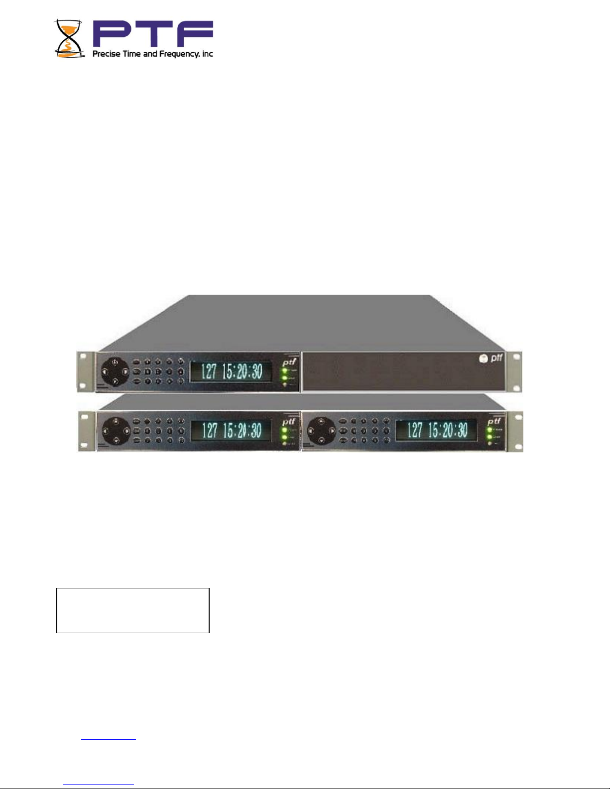
The ptf 3207A provides high-precision time and frequency signals. Its modular design allows factory
customization for a wide range of applications. In its standard configuration, the ptf 3207A functions as
a Time Code Unit which receives an IRIG time code input, synchronizes its internal oscillator to that
input, and produces time code and frequency outputs.
When paired with its internal timing-optimized GPS receiver, the ptf 3207A provides 1x10-12
frequency output accuracy, and better than 30 nS RMS accuracy to UTC (USNO). The ptf 3207A is
available in a 19-inch 1U or 2U chassis with rack mount ears for installation.
This new range of Time and Frequency Clocks incorporates a flexible architecture to meet the most
demanding clock synchronization requirements. The ptf 3207A incorporates a dual redundant
reference source design that enables high-availability of the clock source. To achieve high-availability,
the user configures the ptf 3207A with dual independent GPS receivers and antennas, or with one GPS
antenna/receiver and one time code or 1PPS reference. In addition, the 1U chassis, when configured
with two modules, provides dual redundancy and distribution in a single 1U unit.
Optional oscillator upgrades provide enhanced short term stability when locked to a reference source,
and improved holdover ‘flywheeling’ when a reference source is unavailable. See “P7: Oscillators” on
page 223 for more information.
Features and Options
Three user interfaces are available for managing the ptf 3207A:
• The web interface, available using a browser connected to the Ethernet port
• The command line interface, available from the serial port and standard Ethernet port (telnet)
• The keypad/display interface, available on the front panel of the ptf 3207A

Go to Contents Precise Time and Frequency, Inc., 50L Audubon Road, Wakefield, MA 01880, USA ptf 3207A rev G
The ptf 3207A’s modular design allows factory customization for a wide range of applications. The
following range of features are available in the standard configuration:
• Voltage-controlled temperature-compensated crystal oscillator (VCTCXO)
• 1 PPS Output
• Digital Output 1/10/100 PPS, 1/10/100 kPPS,
1/5/10 MPPS, IRIG B 000 (DCLS)
1 PPM, 1 PHPH, 1 PPH
• Time Code Output (IRIG B 120 1kHz amplitude modulated)
•Alarm clean contact Output
• Time Code Input (AM or DC: IRIG- B)
• Auxiliary Reference Frequency Input (10 MHz)
• Ethernet Port (10/100 Base-T)
• Command Line Interface (Telnet and Serial Port)
• Simple Network Management Protocol (SNMP)
• Web Interface (HTML)
• Vacuum florescent display, 19-button keypad
• 90-264 VAC
In addition, the ptf 3207A’s standard features can be expanded with the following optional
configurations:
• GPS C/A Receiver References
• Network Time Server (NTP)
• T1/E1 Output
• RS485 Control/Monitor interface
• Oscillator Options: OCXO, ULNO, Rubidium
• DC Power Supplies for 18 to 72, and 48 VDC applications
• Redundant power supplies
Optional oscillator upgrades provide enhanced short term stability when locked to a reference source,
and improved holdover ‘flywheeling’ when a reference source is unavailable.
Go to Contents Precise Time and Frequency, Inc., 50L Audubon Road, Wakefield, MA 01880, USA ptf 3207A rev G
******************************************************************************
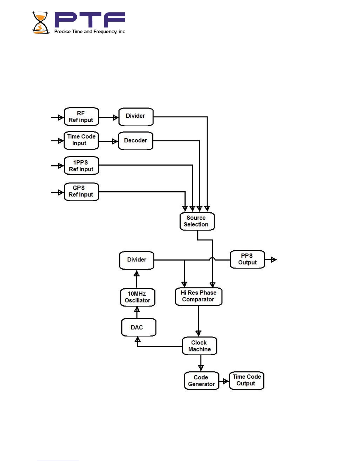
Clock Architecture
The following figure provides a simplified view of the ptf 3207A’s clock architecture.

Go to Contents Precise Time and Frequency, Inc., 50L Audubon Road, Wakefield, MA 01880, USA ptf 3207A rev G
**********************************************************************************
2: System Specifications
Mechanical/Environmental
Operating Temperature:
0 °C to +55 °C (+32 °F to +104 °F)
Maximum Rate of Change:
8 °C per hour
Storage Temperature:
-55 °C to +85 °C (-67 °F to +185 °F)
Humidity: to 95% non-condensing
Operating Altitude:
Maximum 4 km (2.49 mi. or 13147 ft.)
Front Panel Display:
Vacuum Fluorescent Display (VFD)
3.27” x 0.88" (83mm x 20 mm). 256X60
pixels.
Displays startup messages, clock status, time
and day of year, and menu functions.
Keypad: 0–9, F1, F2, UP, DOWN, LEFT, RIGHT,
MAIN, MENU, ENTER
Serial I/O: User-selectable RS-232
communication protocol up to 115200 baud
AC Power Supply
Input:
Input connector: IEC 320 connector
Input voltage range: UL: 100 –240 VAC
Universal, 90 –264 VAC and 110 –370 VDC
Input freq. range: 47 Hz –440 Hz
Output:
+ 5 V, 15 watts, 0 to 3 amps
+ 15 V, 22.5 watts, 0 to 1.5 amps
-15 V, 7.5 watts, 0 to 0.5 amps
Wattage: 45 watts maximum
Power Supply Status:
Visual (green panel LED)
Status LED
Alarm Status LED:
Green LED on with no fault
Amber LED with fault

Go to Contents Precise Time and Frequency, Inc., 50L Audubon Road, Wakefield, MA 01880, USA ptf 3207A rev G
*******************************************************************************
System Time & Frequency Accuracy
The tables below describe system clock accuracy while locked to the reference source indicated.
GPS Receiver Reference
1 PPS Output: UTC(USNO) 20 nS RMS, 100 nS peak
Frequency Output Accuracy: <1 x 10-12 @ 1 day
Frequency/Timing,
Allan Deviation, Stability
1 second 5 x 10-11
10 seconds 1 x 10-11
100 seconds 2 x 10-11
1000 seconds 5 x 10-12
10000 seconds 7 x 10-13
IRIG B (am) Code Output Accuracy: 10 µS to the 1 PPS output
DC Level Shift Code Output Accuracy 200 nS to the 1 PPS output
Time to System Lock <20 min. typical
Time Code Input Reference
1 PPS Output: 10 µS to the incoming code, IRIG B (am)
10 nS to the incoming code, IRIG B (DCLS)
Frequency Output Accuracy: 1x10⁻¹⁰, referenced to 5x10-11 carrier @ 1 day
Stability of Frequency/Timing
Allan Deviation: 5x10⁻⁹ @ 10 sec, referenced to 3x10-11 @ 10 sec carrier
Accuracy of IRIG B 120 (am)
Time Code Output: 10 µS to the incoming code
Accuracy of IRIG B 000 (DC Level Shift) 10 µS to the incoming code (IRIG B am)
Code Output: 10 nS to the incoming code (IRIG B DCLS)

Go to Contents Precise Time and Frequency, Inc., 50L Audubon Road, Wakefield, MA 01880, USA ptf 3207A rev G
*******************************************************************************
1 PPS Input
1 PPS Output: <30 nS to the incoming 1 PPS
Stability of Frequency/Timing
Allan Deviation: 1x10-11 @ 10 sec
Accuracy of IRIG B 120 (am)
Code Output: 10 µS to the incoming 1 PPS
Accuracy of IRIG B 000 (DC Level Shift)
Code output: 100 nS to the incoming 1 PPS
Ext RF Input
Frequency output accuracy is equal to the reference < 1 x 10-12.
Note: Manually set the time and date, when using 1 PPS or Ext RF as the primary references. Set the
date (year) when using IRIG B 000, or IRIG B 120.
Chassis
1U Chassis: Standard 19" EIA Rack System, hardware included
Receiver Size: 1.75 in. x 17.1 in. x 16 in.
Weight: Standard configuration, without options <10 lb.
2U Chassis: Standard 19" EIA Rack System, hardware included
Receiver Size: 3.5 in. x 17.1 in. x 16 in.
Weight: Standard configuration, without options <14 lb.

Go to Contents Precise Time and Frequency, Inc., 50L Audubon Road, Wakefield, MA 01880, USA ptf 3207A rev G
**********************************************************************************
Standard Inputs and Outputs
The following specifications describe the standard inputs and outputs on the ptf 3207A.
Serial I/O Port
The standard serial data port is a bi-directional EIA standard RS-232C interface. The serial data port
baud rate can be configured via the Keypad / Display, or Standard Ethernet port.
Control and monitoring is available through an RS232 port (female 9-contact D connector) and over an
Ethernet port (RJ45 connector). The RS232 port is configured as DTE, receiving data on pin 3 and
transmitting data on pin 2. Pin 5 is chassis ground. Pins 1, 4, and 6 are used for the instrument
summary alarm relay, see table below.
DB9 Connector
Pin #
Function
Comments
1
Alarm Relay NO
Closed when in alarm
2
TX Data (RS232)
3
RX Data (RS 232)
4
Alarm Relay NC
Open when in alarm
5
Ground (RS232)
6
Alarm Relay Common
7
8
Time Print Tx(RS232)
Optional
9
Time Print Gnd(RS232)
Optional
Interface:
RS-232, ground, receive and transmit only.
Data Rates:
4800, 9600 and 19200, 38000, 57,600 bps
Data Bits:
8
Parity:
none
Stop Bits:
1
Connector:
Male 9-pin D subminiature
Pin Assignment:
1------N/C
2------Rx (RS-232)
3------Tx (RS-232)
4------N/C
5------GND
6------
7------
8------
9------
Factory settings:
57,600, 8, N, 1

Go to Contents Precise Time and Frequency, Inc., 50L Audubon Road, Wakefield, MA 01880, USA ptf 3207A rev G
Optional Time Print Interface
The time print interface is optionally available and provides an ASCII formatted string once per second
with the current day of year and time.
Pin connections on the 9 pin D connector are:
RS-232 ground and transmit only.
Data Rate:
same as selected for main serial I/O
Data Bits:
8
Parity:
none
Stop Bits:
1
Connector:
Male 9-pin D subminiature
Pin Assignment:
1------
2------
3------
4------
5------
6------
7------
8------ Tx (RS-232)
9------ GND
Format of Time Print Output
<SOH>DDD:HH:MM:SSQ<CR><LF>
Format:
<SOH> Hex 01 The start bit of the <SOH> character is transmitted on time.
Q Time quality indicator. Represented by:
space ( ASCII 0x20, Locked, maximum accuracy)
?(ASCII 0x3F, reference source unavailable)

Go to Contents Precise Time and Frequency, Inc., 50L Audubon Road, Wakefield, MA 01880, USA ptf 3207A rev G
ENET –Ethernet Port
The Ethernet port interface has a standard RJ-45 connector that provides IEEE 802.3 frame 10/100
Base-T Ethernet. The ptf 3207A can optionally be factory configured as a Network Time Protocol (NTP)
server, which can be used to synchronize client computer clocks over a network.
J2 Input –IRIG B 120 (am) Time Code
Time Code Input Specifications
Format:
IRIG-B120
Amplitude (AM): 0.5V to 3V Vp-p into 50 ohms
Ratio (AM): 3:1 ±10%
Impedance: 50 ohms
Direction: Forward
Quantity: 1
Connector: Female BNC
Accuracy Refer to “System Time & Frequency Accuracy”
J3 Output –RF Output
Frequency: 10 MHz
Amplitude: 1 V rms, into 50 Ohms
Quantity: 1
Connector: Female BNC
Factory Configuration: Enabled
J4 Output –Digital Output
Rate: 1 PPS, 10 PPS, 100 PPS, 1 kPPS, 10 kPPS, 100 kPPS, 1 MPPS,
5MPPS, 10 MPPS, 100MPPS, PPM, PHH, PPH
Duty cycle: 40-60% ± 10% , or 100ns pulse width
Amplitude (TTL): TTL Levels into 50 Ohms
Quantity: 1
Connector: Female BNC
Factory Configuration: 1 PPS

Go to Contents Precise Time and Frequency, Inc., 50L Audubon Road, Wakefield, MA 01880, USA ptf 3207A rev G
J5 Output –Time Code Output to IEEE1344
Time Code Output Specifications - IRIG B120 modulated (am)
Format: IRIG-B120
Amplitude (AM): 3 Vp-p, into 50 Ohms
Ratio (AM): 3:1 ±10%
Quantity: 1
Connector: Female BNC
Default Configuration: Enabled
IRIG-B-120 IS DEFINED IN IRIG STANDARD 200-04 AS:
• Format B 100 pps
• 1 = Sine wave amplitude modulated
• 2 = 1KHz carrier/1mSec resolution
• 0 = BCD TOY,CF,SBS
IEEE1344 IS DEFINED IN IEEE1344-1995(R2001) ANNEX F AS:
IRIG-B format, <sync>SS:MM:HH:DDD<control bits> <binary seconds>
where :
<sync> is the on time marker
SS seconds 00-59 (60 during leap seconds)
MM minutes 00-59
HH hour of day 00-23
DDD day of year 001-366
<control> 27 binary control characters, see Table 1 (reference IEEE1344)
<binary seconds> binary seconds of day
Binary Time quality Estimated Time Error (ETE)
1111 Initial condition clock unlocked or 10Sec < ETE
1011 Clock unlocked and 1Sec < ETE <= 10Sec
1010 Clock unlocked and 100mSec < ETE <= 1Sec
1001 Clock unlocked and 10mSec < ETE <= 100mSec
1000 Clock unlocked and 1mSec < ETE <= 10mSec
0111 Clock unlocked and 100uSec < ETE <= 1mSec
0110 Clock unlocked and 10uSec < ETE <= 100uSec
0101 Clock unlocked and 1uSec < ETE <= 10uSec
0100 Clock unlocked and 100nSec < ETE <= 1uSec
0011 Clock unlocked and 10nSec < ETE <= 100nSec
0010 Clock unlocked and 1nSec < ETE <= 10nSec
0001 Clock unlocked and ETE <= 1nSec
0000 Clock locked to a reference source
Many IRIG reader devices only decode the BCD time-of-year (TOY) portion of the IRIG frame. Reader
devices designed to the IRIG-B122, B002 standard should be compatible with the ptf 3207A’s time
code outputs.

Go to Contents Precise Time and Frequency, Inc., 50L Audubon Road, Wakefield, MA 01880, USA ptf 3207A rev G
DB9 - ALARM Output
Contacts: Type C
High Z: Power off
High Z: Alarm (enabled alarm fault)
Low Z: Normal (no enabled alarm faults)
Drive: Relay contacts
Max. Voltage: 25 VDC
Max. Current: 50 mA
Quantity: 1
Connector: DB9
The ptf 3207A first synchronizes to IRIG-B-120 w/ IEEE1344 when the Time Quality control bits are =
0000. The ptf 3207A remains synchronized (Locked) while the Time Quality control bits are 0000
through 0101 (ETE < 10uSec).
The ptf 3207A remains synchronized (Locked) while the Time Quality control bits are 0000 through
0101 (ETE < 1uSec). The ptf 3207A uses the incoming local time offset information to convert the time
internally to receiver time, which is always UTC. Displayed time will be according to the local time
offset, DST etc. set internally on the system menu
Manual Leap Second Entry
The Manual Leap Second Entry is configurable via the Keypad / Display, RS232 and the Network
port via telnet and HTML. This function allows the user to enter leap second data. This mode of
operation will allow the user to maintain UTC with the ptf 3207A clock without an external time
reference providing leap second data or in a standalone mode (i.e. without a time reference).
Locked reference sources containing leap second data (GPS and IRIG-B w/ IEEE1344) take priority over
the manual leap second entry.
Manual leap second data is applied to the ptf 3207A UTC TOD when locked to any reference source
that does not contain leap second data.
The manual leap second data will be applied to the clock at the end of the current quarter that it was
entered at UTC midnight on the last day of June, or December

Go to Contents Precise Time and Frequency, Inc., 50L Audubon Road, Wakefield, MA 01880, USA ptf 3207A rev G
*****************************************************************************
Certifications
UL, C-UL: UL 1950/CSA 22.2 950, Standard for Safety, Information Technology
Equipment (ITE)
FCC: FCC Part 15, Subpart B
CE: 89/336/EEC EMC Directive
73/23/EEC Low Voltage Safety Directive
IEC 60950 Safety of Information Technology Equipment (ITE)

Go to Contents Precise Time and Frequency, Inc., 50L Audubon Road, Wakefield, MA 01880, USA ptf 3207A rev G
**********************************************************************************
3: Installation/Configuration
Installing the GNS Antenna
For units that include the GPS, Glonass, Galileo, or multi receiver options, install the GNS antenna and
cable as described below.
Selecting a GNS Antenna Site Outdoors
Select a site that...
•Is the highest point available
• Offers a full 360° view horizontally, to within 10° vertically of the horizon
• Is higher than neighboring buildings/obstructions
• Is protected from strong radio frequency (RF) and microwave transmissions
• Is set away from RF-reflective surfaces that cause multipath interference
• Is set 3 ft. (1 m) away from other GPS antennas
Avoid...
• Mounting the antenna between tall buildings or next to walls and equipment
• Cable runs from the antenna to the receiver that exceed the specified length
• Patching multiple cables together to make a single cable run
• Running the cable through bulkheads and alongside high-energy cables
• Crimping or damaging the cable
Blocked signals and multipath cancellation significantly increase GNS acquisition time. Multipath
cancellation is caused by reflected signals that reach the antenna out of phase with the direct signal
due to vertical reflective objects positioned to the side and above the antenna. To solve these
problems, mast mount the antenna at least 1 meter away from and above the reflecting surface.
Mounting the GNS Antenna
Mount the GNS antenna on an antenna mast (recommended) or on the peak of a building.
A mast is included with the GNS antenna mounting kit.
If you use a tall mast longer than 10 ft. (3.048 m), use guy wires for stabilization.
Notes:
• The ptf 3207A requires a 5 Volt-compatible antenna.
• Use an active splitter to connect a GNS antenna to multiple receivers. Also insure the splitter
includes one "DC pass through" channel for powering the antenna, and that the other channels
present a dummy load to the other receivers . The receiver front end has a sensing circuit to
insure the antenna is not over or under the DC load. Without a dummy load the receivers will
indicate a fault, and will not lock even though sufficient satellites may be in view. Avoid using
BNC “T” connectors.
• The L1 GPS antenna is designed to operate with up to 150 ft. (60.96 m) of RG-59 coax cable.

Go to Contents Precise Time and Frequency, Inc., 50L Audubon Road, Wakefield, MA 01880, USA ptf 3207A rev G
Refer to Figure 4: GPS Signal Strength Requirements.The required external gain at the GPS receiver’s
ANTENNA connector is between 15 and 25 dB.
For example, the GPS antenna provides approximately 35 dB of gain. If one subtracts the
16 dB loss of a 150 foot RG-59 coax antenna cable, the external gain reaching the ANTENNA connector
is between 19 dB, which meets the requirement. Abide by the minimum input gain requirements when
using other cable types and GPS antennas.
Other factors, such as radiation, coverage, VSWR, and input impedance also affect system
performance. It is recommended to use the standard antenna and cable provided.
GNS-related Accessories
The following options can be obtained to:
• Protect against lightning and field-induced electrical surges.
• Connect multiple GPS receivers to a single antenna.
• Extend the range of the GPS antenna cable.
LKIT - Lightning Arrestor
Lightning may damage GPS system components and receiving equipment, even without a direct hit,
resulting in costly repairs and critical interruption of service. The lightning arrestor is designed to work
in conjunction with a low-resistance, low-inductance ground to protect your GPS receiver and
elements of the antenna system from lightning discharges and field-induced electrical surges. In-line
lightning arrestors are mounted between the antenna and the point where the cable enters the
building and require no additional power or wiring except the ground lead.
ptf 1231A - Antenna Distribution Amplifier
An antenna distribution amplifier may be used to drive multiple GPS receivers using a single antenna.
The ptf 1231A has built-in amplification to overcome losses.
HGAN - High Gain Antenna
High gain antennas overcome signal attenuation in by amplifying the GPS signal. The high gain antenn
has a gain of 50 db and can be mounted in place of the standard antenna.
Go to Contents Precise Time and Frequency, Inc., 50L Audubon Road, Wakefield, MA 01880, USA ptf 3207A rev G
*****************************************************************************
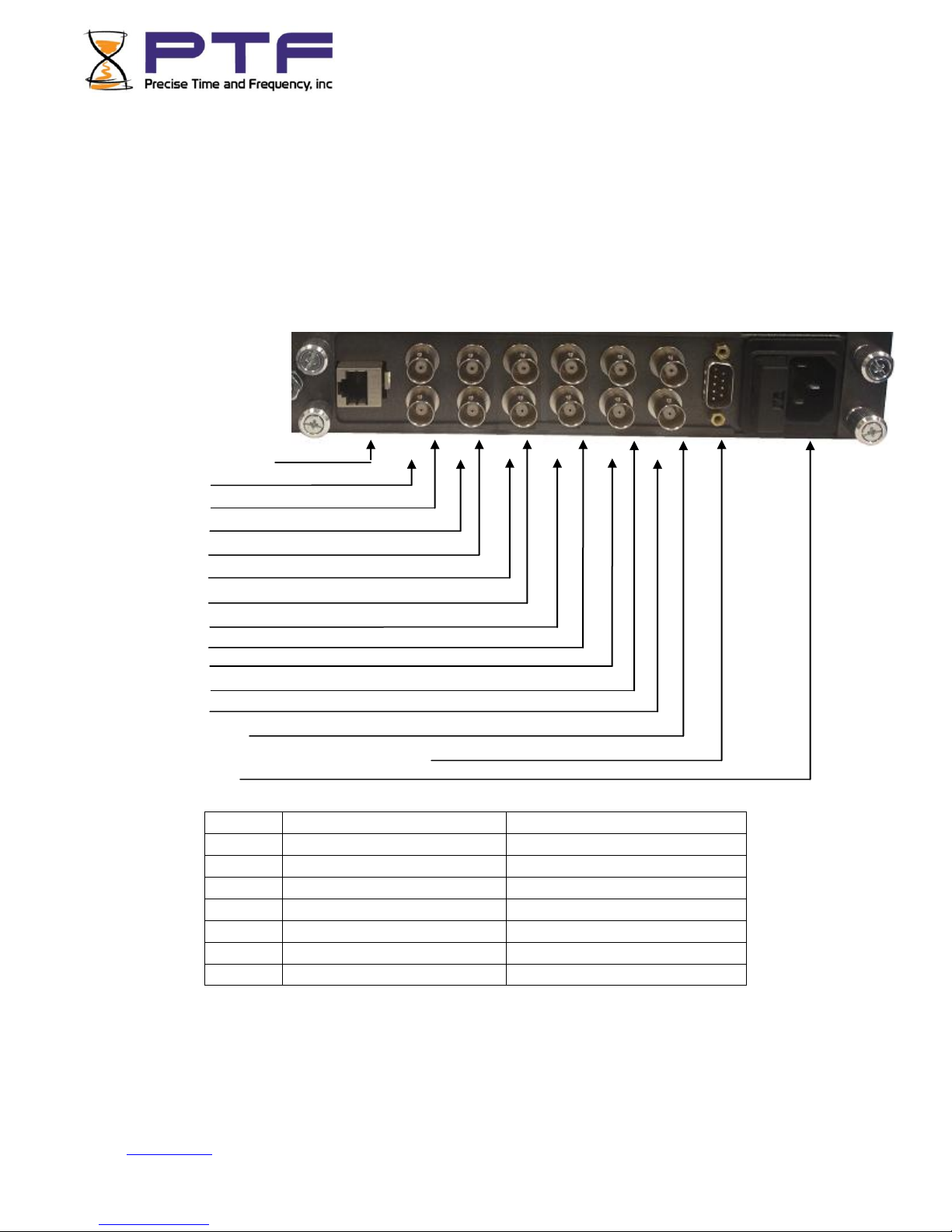
Making Additional Connections
Make the following connections to the standard input/output connectors on the ptf 3207A rear panel:
•The ANTENNA connector to a GNS antenna cable.
•The ENET Ethernet port (RJ-45) to an Ethernet network using Cat 5 cable. This
connection is needed to manage the ptf 3207A remotely, or to use the optional NTP function.
• The SERIAL I/O connector to a PC using an RS-232 null modem cable.
•J1 thru J12 as needed.
Rear View of single
Module
Connections
J1 (Ethernet, RJ45)
J2 (lower)
J3 (upper)
J4(lower)
J5(upper)
J6(lower)
J7(upper)
J8(lower)
J9(upper)
J10(lower)
J11(upper)
J12(lower)
J13(upper)
J14(RS232 control/monitor/alarms relay)
J15(AC Mains)
Pin #
Function
Comments
1
Alarm Relay NO
Closed when in alarm
2
TX Data (RS232)
3
RX Data (RS 232)
4
Alarm Relay NC
Open when in alarm
5
Ground (RS232)
6
Alarm Relay Common
7, 8, 9
Not used
NOTE: There are many different configurations that necessarily require different input/output
connections. In some cases many of the connections will be blank. For each specific instrument
connections are detailed on a label above the input/output connectors. Where this label differs from
the connections outlined above, the label always takes precedence.

Go to Contents Precise Time and Frequency, Inc., 50L Audubon Road, Wakefield, MA 01880, USA ptf 3207A rev G
Connecting the Power Supply
Warning: Ensure that a disconnect device, such as a switch, with the appropriate voltage/
current rating is provided when operating/installing the ptf 3207A.
Connect the Power Supply to a power source. The green POWER LED indicates that the ptf 3207A is
receiving power.
Notes for optional DC power supplies:
• Use a 15 amp circuit breaker in series with the DC power source; avoid connecting directly to a
DC power source without the breaker.
• 14 gage wire is the minimum recommended for DC power source hookup.
• DC Power Supply Only to be used in a restricted access area.
• The screw torque range on the Power Terminal Block is 5 to 8 inch pounds.
•When connecting to a DC power source, first connect the positive power cable to “+” on the
power supply, then connect the negative power supply cable to “-”.
Upon receiving power, the ptf 3207A goes through its startup sequence;
Fault LED flashes GREEN rapidly while the operating system is booting.
After approximately 30 seconds, the ptf 3207A display will indicate it is doing self tests
After successful completion of self tests the display will indicate "Ready"
Next, the display will show the initial menu of status screens
Finally, if no key is pressed on the keypad, the last selected status screen will display.
Before using the ptf 3207A for the first time it may be necessary to set up certain parameters such as
Ethernet settings, time displays, etc. This is done by use of the menu system, accessible through either
the front panel keypad, serial, telnet, or web browser capabilities. Please see the next section.

Go to Contents Precise Time and Frequency, Inc., 50L Audubon Road, Wakefield, MA 01880, USA ptf 3207A rev G
Navigating the front panel menu system
Access via the front panel keypad can be protected by use of a four number “PIN”.
A special “hidden” menu command, KEYPAD-PIN is available to select a PIN of
your choice. If this entry is set to 0000 the pin is not active and access to the setup
menus is granted just by pressing the “MENU” key. Any other number up to 9999
will activate the PIN and before any menu items can be changed the PIN must be
entered. The PIN will remain active during an editing session. Once an editing
session is complete, or at any time during the editing process, pressing the “MENU”
key will reset access and to re-enter edit mode the PIN will need to be re-entered.
Press MENU - this will display the menu screen options. To scroll through menu items press the
(RIGHT ARROW) key. The cursor on the left side of the screen will highlight each menu
item in turn.
TIP: To more rapidly move through the menu items, you can use the (DOWN ARROW)
key. This will page through the screens 4 items at a time. When the screen containing
the item you require appears, you can use (RIGHT ARROW) and (LEFT
ARROW) keys to place the cursor next to the required item.
Menu items can be either string, integer or "special format" items. Dependent upon the type
of item to be edited the menu edit screen will present different formats.
Scroll through the menu items as described above until the cursor highlights the required
menu item
String edits
Press ENTER - the available string choices will be displayed, with the cursor against the
currently selection. Using the (RIGHT ARROW) and (LEFT ARROW) keys highlight the
required selection, then press the ENTER key. The new selection will be stored.
TIP: To exit without storing the new value press the MENU key.
Integer Edits
Press ENTER - the integer edit screen is presented, displaying the current integer value. Use the
number keys to enter a new value, where applicable to enter a - (minus) sign use the F1 key,
where applicable to enter a . (decimal point, i.e. for decimal fractions)) use the F2 key, then
press enter to save and store the new value.
TIP: To exit without storing the new value press the MENU key.
Other manuals for 3207A
2
Table of contents
Other PTF Receiver manuals


