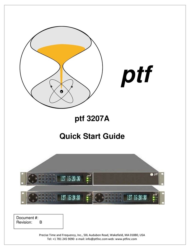
PTF 3207A User manual

Go to Contents Precise Time and Frequency, LLC., 50L Audubon Road, Wakefield, MA 01880, USA ptf 3207A rev U
Certificate of Conformance
This certificate confirms that the following equipment:
Unit type: ptf 3207A GlobalTyme2 GNS Receiver
Serial Number: _904-01480-02___
has successfully passed a FINAL ACCEPTANCE TEST and conforms
in all respects of form, fit, and function to current specifications, including
regulatory requirements and certifications.
This part conforms to RoHS-2 Standards for material content with no
exemptions. This part conforms to REACH Standards for material
content. REACH compliant level 173,SVHC’S
Manual will be found at:
http://ptf-llc.com/main/products/frequency-and-time-reference-
standards/gpsgns-freq-and-time-ref-3207a/
Click on Documentation
Inspected and verified by: Date:
Stacy Roope 06/04/2020
_____________________ _____________________
For Precise Time and Frequency, LLC

Go to Contents Precise Time and Frequency, LLC., 50L Audubon Road, Wakefield, MA 01880, USA ptf 3207A rev U
Declaration of Conformity
This certificate confirms that the following equipment:
Unit type: ptf 3207A
is in conformity with the relevant provisions of the following standard(s)
or other normative document(s):
EU EMC Directive 2014/30/EU:
Electromagnetic compatibility and Radio spectrum Matters (ERM); Electromagnetic
Compatibility (EMC) standard for radio equipment and services; Part 1: Common
technical requirements
EN 55022:2006
Information technology equipment —Radio disturbance characteristics - Limits and
methods of measurement
EN 61000-4-2: 2001
Electromagnetic compatibility (EMC) - Part 4-2: Testing and measurement techniques -
Electrostatic discharge immunity test
EN 61000-4-3:2006
Electromagnetic compatibility (EMC) - Part 4-3: Testing and measurement techniques -
Radiated, radiofrequency, electromagnetic field immunity test
EN 61000-4-4:2004
Electromagnetic compatibility (EMC) - Part 4-4: Testing and measurement techniques -
Electrical fast transient/burst immunity test
EN 61000-4-5:2006
Electromagnetic compatibility (EMC) - Part 4-4: Testing and measurement techniques -
Surge immunity test
EN 61000-4-6:2005
Electromagnetic compatibility (EMC) - Part 4-4: Testing and measurement techniques -
Electrical fast transient/burst immunity test
EN 61000-4-11:2004
Electromagnetic compatibility (EMC) - Part 44: Testing and measurement techniques
—Voltage Dips and Short Interruptions immunity test
ISO 7637-2:2004
Road vehicles - Electrical disturbances from conduction and coupling - Part 2:
Electrical transient conduction along supply lines only
EN 61000-3-2:2006 +A1:2009 +A2:2009

Go to Contents Precise Time and Frequency, LLC., 50L Audubon Road, Wakefield, MA 01880, USA ptf 3207A rev U
Electromagnetic compatibility (EMC) - Part 32: Limits - Limits for harmonic and current
emissions (equipment input current ≤ 16 A per phase)
EN 61000-3-3:1995
Electromagnetic compatibility (EMC) - Part 3-3: Limits - Limitation of voltage changes,
voltage fluctuations and flicker in public low-voltage supply systems, for equipment
with rated current ≤ 16 A per phase and not subject to conditional connection
EN 55016-1-1:2007
Specification for radio disturbance and immunity measuring apparatus and methods —
Part 1-1: Radio disturbance and immunity measuring apparatus —Measuring
apparatus Amendment1 (2007)
ClSPR16-1-2:2003
Specification for radio disturbance and immunity measuring apparatus and methods —
Part 1-2: Radio disturbance and immunity measuring apparatus —Ancillary equipment
—Conducted disturbances 5
Amendment1 (2004)
Amendment 2 (2006)
EN 55016-1-4:2007
Specification for radio disturbance and immunity measuring apparatus and methods -
Part 1-4: Radio disturbance and immunity measuring apparatus - Ancillary equipment -
Radiated disturbances
EN 55016-2-3:2004
Specification for radio disturbance and immunity measuring apparatus and methods -
Part 2-3: Methods of measurement of disturbances and immunity —Radiated
disturbance measurements
Amendment 1 (2005)
EN 55016-4-2:2003
Specification for radio disturbance and immunity measuring apparatus and methods —
Part 4-2: Uncertainties, statistics and limit modeling —Measurement instrumentation
uncertainty
EU Low Voltage Directive 2014/35/EU
2014/35/EU Safety of Information Technology Equipment,
including electrical business equipment
IEC 60950-1:2005/AMD2:2013 +A2 Safety of Information technology equipment
EU ROHS directive compliance according to Directive 2015/863

Go to Contents Precise Time and Frequency, LLC., 50L Audubon Road, Wakefield, MA 01880, USA ptf 3207A rev U
NOTE: This manual is best viewed in electronic form. Clicking on any of
the Contents items will take you to that item. To return to the
contents page, click on the "Go to Contents" link at the foot of the
page.
View of the Dual Module Rear Panel
Notices
Copyright © 2016, Precise Time and Frequency, Inc.
All rights reserved. Printed in U.S.A.
All product names, service marks, trademarks, and registered trademarks
used in this document are the property of their respective owners.

Go to Contents Precise Time and Frequency, LLC., 50L Audubon Road, Wakefield, MA 01880, USA ptf 3207A rev U
Contents
1: Equipment Overview ..............................................................................................................................9
Declaration of Compliance......................................................................................................................9
ptf 3207A Time and Frequency System Description and Features.......................................................11
Clock Architecture.................................................................................................................................13
2: System Specifications............................................................................................................................14
Mechanical/Environmental ..................................................................................................................14
Dynamic Characteristics........................................................................................................................14
Front Panel Display: ..............................................................................................................................14
Serial I/O: User-selectable RS-232...............................................................................................14
AC Power Supply...................................................................................................................................14
Status LED .............................................................................................................................................14
System Time & Frequency Accuracy.....................................................................................................15
Standard Inputs and Outputs................................................................................................................17
ENET –Ethernet Port ............................................................................................................................19
ADDITIONAL FEATURES.........................................................................................................................22
3: Installation/Configuration.....................................................................................................................23
Installing the GNS Antenna...................................................................................................................23
GNS-related Accessories.......................................................................................................................24
Making Additional Connections............................................................................................................25
Half-Width Module...............................................................................................................................25
Full width Module.................................................................................................................................26
Connecting the Power Supply...............................................................................................................27
Navigating the front panel menu system .............................................................................................28
Configuring Ethernet Settings...............................................................................................................30
Using the Command Line Interface ......................................................................................................33
Operating Modes –Survey, Fixed, Mobile............................................................................................41
4. User Interfaces......................................................................................................................................43
Time and Status Displays ......................................................................................................................44

Go to Contents Precise Time and Frequency, LLC., 50L Audubon Road, Wakefield, MA 01880, USA ptf 3207A rev U
Additional status displays .....................................................................................................................45
NMEA Protocol......................................................................................................................................46
5. Configuring and Using External Input Ports..........................................................................................50
Introduction..........................................................................................................................................50
IRIG B (AM)............................................................................................................................................50
DIGITAL Input........................................................................................................................................52
IRIG B (DCLS) .........................................................................................................................................52
For IRIG DCLS Input...............................................................................................................................52
1PPS ......................................................................................................................................................52
10MHz RF..............................................................................................................................................53
Note: The output time codes will reflect whatever time and date were manually set (if any),
incrementing by 1 second each second................................................................................................54
6. Default Settings.....................................................................................................................................55
7. Sales and Customer Assistance.............................................................................................................56
8. Revision Record.....................................................................................................................................57

Go to Contents Precise Time and Frequency, LLC., 50L Audubon Road, Wakefield, MA 01880, USA ptf 3207A rev U
***************************************************************************
1: Equipment Overview
Declaration of Compliance
Certificate of Conformance
This certificate confirms that the ptf 3207A has been tested and complies
with the following CE standards to comply with the
requirements for CE Marking:
EU EMC Directive 2004/108/EC:
EN 301 489-17 v2.2.1 Electromagnetic compatibility and Radio spectrum Matters (ERM);
Electromagnetic Compatibility (EMC) standard for radio equipment; Part 17: Specific
conditions for Broadband Data Transmission Systems
EN 301 489-1 v1.9.2 Electromagnetic compatibility and Radio spectrum Matters (ERM);
Electromagnetic Compatibility (EMC) standard for radio equipment and services; Part 1:
Common technical requirements
EN 300 440-2 v1.4.1 - Radio equipment to be used in the 1 GHz to 40GHz frequency range
EN 62479: 2010 Human exposure to magnetic fields
EN 60 950-1 Information technology equipment - Safety Part 1
EN 55022:2006
Information technology equipment —Radio disturbance characteristics - Limits and methods
of measurement
EN 61000-4-2: 2001
Electromagnetic compatibility (EMC) - Part 4-2: Testing and measurement techniques -
Electrostatic discharge immunity test
EN 61000-4-3:2006
Electromagnetic compatibility (EMC) - Part 4-3: Testing and measurement techniques -
Radiated, radiofrequency, electromagnetic field immunity test
EN 61000-4-4:2004
Electromagnetic compatibility (EMC) - Part 4-4: Testing and measurement techniques -
Electrical fast transient/burst immunity test
EN 61000-4-5:2006
Electromagnetic compatibility (EMC) - Part 4-4: Testing and measurement techniques - Surge
immunity test
EN 61000-4-6:2005
Electromagnetic compatibility (EMC) - Part 4-4: Testing and measurement techniques -
Electrical fast transient/burst immunity test
EN 61000-4-11:2004
Electromagnetic compatibility (EMC) - Part 44: Testing and measurement techniques —
Voltage Dips and Short Interruptions immunity test
ISO 7637-2:2004

Go to Contents Precise Time and Frequency, LLC., 50L Audubon Road, Wakefield, MA 01880, USA ptf 3207A rev U
Road vehicles - Electrical disturbances from conduction and coupling - Part 2: Electrical
transient conduction along supply lines only
EN 61000-3-2:2006 +A1:2009 +A2:2009
Electromagnetic compatibility (EMC) - Part 32: Limits - Limits for harmonic and current
emissions (equipment input current ≤ 16 A per phase)
EN 61000-3-3:1995
Electromagnetic compatibility (EMC) - Part 3-3: Limits - Limitation of voltage changes, voltage
fluctuations and flicker in public low-voltage supply systems, for equipment with rated current ≤
16 A per phase and not subject to conditional connection
EN 55016-1-1:2007
Specification for radio disturbance and immunity measuring apparatus and methods —Part 1-
1: Radio disturbance and immunity measuring apparatus —Measuring apparatus
Amendment1 (2007)
ClSPR16-1-2:2003
Specification for radio disturbance and immunity measuring apparatus and methods —Part 1-
2: Radio disturbance and immunity measuring apparatus —Ancillary equipment —Conducted
disturbances 5
Amendment1 (2004), Amendment 2 (2006)
EN 55016-1-4:2007
Specification for radio disturbance and immunity measuring apparatus and methods - Part 1-4:
Radio disturbance and immunity measuring apparatus - Ancillary equipment - Radiated
disturbances
EN 55016-2-3:2004
Specification for radio disturbance and immunity measuring apparatus and methods - Part 2-3:
Methods of measurement of disturbances and immunity —Radiated disturbance
measurements
Amendment 1 (2005)
EN 55016-4-2:2003
Specification for radio disturbance and immunity measuring apparatus and methods —Part 4-
2: Uncertainties, statistics and limit modeling —Measurement instrumentation uncertainty
EU Low Voltage Directive 2006/95/EC
EN 60950-1:2006 Safety of Information Technology Equipment,
+A1+A11+A12including electrical business equipment
EU ROHS directive compliance according to Directive 2015/863
This part conforms to RoHS-3 Standards for material content with no exemptions.
This part conforms to REACH Standards for material content.
REACH compliant level 173, SVHC’s
Signed: Date:
_____________________ _January 9, 2018____
For Precise Time and Frequency, LLC

Go to Contents Precise Time and Frequency, LLC., 50L Audubon Road, Wakefield, MA 01880, USA ptf 3207A rev U
ptf 3207A Time and Frequency System Description and Features
The ptf 3207A provides high-precision time and frequency signals. Its modular design allows factory
customization for a wide range of applications. In its standard configuration, the ptf 3207A functions as
a stand-alone unit which can receive an IRIG time code input, 10MHz input, or 1PPS input,
synchronizes its internal oscillator to that input, and produces time code and frequency outputs.
When paired with its internal timing-optimized GNS receiver, the ptf 3207A provides 1x10-12
frequency output accuracy, and better than 30 nS RMS accuracy to UTC (USNO). The ptf 3207A is
available in a 19-inch 1U or 2U chassis with rack mount ears for installation.
This new range of Time and Frequency Clocks incorporates a flexible architecture to meet the most
demanding clock synchronization requirements. The ptf 3207A incorporates a dual redundant
reference source design that enables high-availability of the clock source. To achieve high-availability,
the user configures the ptf 3207A with dual independent GPS receivers and antennas, or with one GPS
antenna/receiver and one time code or 1PPS reference. In addition, the 1U chassis, when configured
with two modules, provides dual redundancy and distribution in a single 1U unit.
Optional oscillator upgrades provide enhanced short term stability when locked to a reference source,
and improved holdover ‘flywheeling’ when a reference source is unavailable.
The ptf 3207A-TCG configuration is designed to provide additional time code features, in particular this
configuration offers count up/down capability and an additional I2C interface to provide remote
control for loading preset count up/down time, start, hold, and direction (up/down).
Features and Options
Three user interfaces are available for managing the ptf 3207A:
• The web interface, available using a browser connected to the Ethernet port
• The command line interface, available from the serial port and standard Ethernet port (telnet)
• The keypad/display interface, available on the front panel of the ptf 3207A
In addition the unit includes SNMP v1,2,and 3.

Go to Contents Precise Time and Frequency, LLC., 50L Audubon Road, Wakefield, MA 01880, USA ptf 3207A rev U
The ptf 3207A’s modular design allows factory customization for a wide range of applications. The
following range of features are available in the standard configuration:
• Voltage-controlled temperature-compensated crystal oscillator (VCTCXO)
• 1 PPS Output
• Digital Output 1/10/100 PPS, 1/10/100 kPPS, (PPS=Pulses Per Second)
1/5/10 MPPS, IRIG B 000 (DCLS)
1 PPM (minute), 1 PHH (half hour), 1 PPH (hour),
Pulse widths are settable in 100 nano second steps
• Time Code Output (IRIG B 120 1kHz amplitude modulated) , NASA 36
• Count down pseudo IRIG B time code output (ptf 3207A-TCG only)
• Alarm clean contact Output
• Time Code Input (AM or DC: IRIG- B)
• Auxiliary Reference Frequency Input (10 MHz)
• Ethernet Port (10/100 Base-T)
• Command Line Interface (Telnet and Serial Port)
• Simple Network Management Protocol (SNMP)
• Web Interface (HTML)
• Vacuum florescent display, 19-button keypad
• 90-264 VAC
In addition, the ptf 3207A’s standard features can be expanded with the following optional
configurations:
• GPS C/A Receiver References
• Network Time Server (NTP)
• T1/E1 Output
• RS485 Control/Monitor interface
• Oscillator Options: OCXO, ULNO, Rubidium
• DC Power Supplies for 18 to 72, and 48 VDC applications
• Redundant power supplies
Optional oscillator upgrades provide enhanced short term stability when locked to a reference source,
and improved holdover ‘flywheeling’ when a reference source is unavailable.

Go to Contents Precise Time and Frequency, LLC., 50L Audubon Road, Wakefield, MA 01880, USA ptf 3207A rev U
**********************************************************************************
2: System Specifications
Mechanical/Environmental
Operating Temperature:
-25 °C to +55 °C (-13 °F to +104 °F)
Maximum Rate of Change:
8 °C per hour
Storage Temperature:
-55 °C to +85 °C (-67 °F to +185 °F)
Humidity: to 95% non-condensing
Operating Altitude:
Maximum 4 km (2.49 mi. or 13147 ft.)
Dynamic Characteristics:
Velocity 1000 knots (515 m/s)
Maximum at altitudes
< 60,000 ft.
Acceleration 4g maximum
Jerk 5 m/s3
Vibration 7.7G rms per Mil.
Standard 810E
Front Panel Display:
Vacuum Fluorescent Display (VFD)
3.27” x 0.88" (83mm x 20 mm). 256X60
pixels.
Displays startup messages, clock status, time
and day of year, and menu functions.
Keypad: 0–9, F1, F2, UP, DOWN, LEFT, RIGHT,
MAIN, MENU, ENTER
Serial I/O: User-selectable RS-232
communication protocol up to 115200 baud
AC Power Supply
Input:
Input connector: IEC 320 connector
Input voltage range: UL: 100 –240 VAC
Universal, 90 –264 VAC and 110 –370 VDC
Input freq. range: 47 Hz –440 Hz
Output:
+ 5 V, 15 watts, 0 to 3 amps
+ 15 V, 22.5 watts, 0 to 1.5 amps
-15 V, 7.5 watts, 0 to 0.5 amps
Wattage: 45 watts maximum
Power Supply Status:
Visual (green panel LED)
Status LED
Alarm Status LED:
Green LED on with no fault
Amber LED with fault

Go to Contents Precise Time and Frequency, LLC., 50L Audubon Road, Wakefield, MA 01880, USA ptf 3207A rev U
*******************************************************************************
System Time & Frequency Accuracy
The tables below describe system clock accuracy while locked to the reference source indicated.
GPS Receiver Reference
1 PPS Output: UTC(USNO) 20 nS RMS, 100 nS peak
Frequency Output Accuracy: <1 x 10-12 @ 1 day
Frequency/Timing,
Allan Deviation, Stability
1 second 5 x 10-11
10 seconds 1 x 10-11
100 seconds 2 x 10-11
1000 seconds 5 x 10-12
10000 seconds 7 x 10-13
IRIG B (am) Code Output Accuracy: 10 µS to the 1 PPS output
DC Level Shift Code Output Accuracy 200 nS to the 1 PPS output
Time to System Lock <20 minutes typical
Time Code Input Reference
1 PPS Output: 10 µS to the incoming code, IRIG B (am)
10 nS to the incoming code, IRIG B (DCLS)
Frequency Output Accuracy: 1x10⁻¹⁰, referenced to 5x10-11 carrier @ 1 day
Stability of Frequency/Timing
Allan Deviation: 5x10⁻⁹ @ 10 sec, referenced to 3x10-11 @ 10 sec carrier
Accuracy of IRIG B 120 (am)
Time Code Output: 10 µS to the incoming code
Accuracy of IRIG B 000 (DC Level Shift) 10 µS to the incoming code (IRIG B am)
Code Output: 10 nS to the incoming code (IRIG B DCLS)

Go to Contents Precise Time and Frequency, LLC., 50L Audubon Road, Wakefield, MA 01880, USA ptf 3207A rev U
*******************************************************************************
1 PPS Input
1 PPS Output: <30 nS to the incoming 1 PPS
Stability of Frequency/Timing
Allan Deviation: 1x10-11 @ 10 sec
Accuracy of IRIG B 120 (am)
Code Output: 10 µS to the incoming 1 PPS
Accuracy of IRIG B 000 (DC Level Shift)
Code output: 100 nS to the incoming 1 PPS
Ext RF Input
Frequency output accuracy is equal to the reference < 1 x 10-12.
Note: Manually set the time and date, when using 1 PPS or Ext RF as the primary references. Set the
date (year) when using IRIG B 000, or IRIG B 120.
Chassis
1U Chassis: Standard 19" EIA Rack System, hardware included
Receiver Size: 1.75 in. x 17.1 in. x 16 in.
Weight: Standard configuration, without options <10 lb.
2U Chassis: Standard 19" EIA Rack System, hardware included
Receiver Size: 3.5 in. x 17.1 in. x 16 in.
Weight: Standard configuration, without options <14 lb.

Go to Contents Precise Time and Frequency, LLC., 50L Audubon Road, Wakefield, MA 01880, USA ptf 3207A rev U
**********************************************************************************
Standard Inputs and Outputs
The following specifications describe the standard inputs and outputs on the ptf 3207A.
Serial I/O Port
The standard serial data port is a bi-directional EIA standard RS-232C interface. The serial data port
baud rate can be configured via the Keypad / Display, or Standard Ethernet port.
Control and monitoring is available through an RS232 port (female 9-contact D connector) and over an
Ethernet port (RJ45 connector). The RS232 port is configured as DTE, receiving data on pin 3 and
transmitting data on pin 2. Pin 5 is chassis ground. Pins 1, 4, and 6 are used for the instrument
summary alarm relay, see table below.
DB9 Connector
Pin #
Function
Comments
1
Alarm Relay NO
Closed when in alarm
2
TX Data (RS232)
3
RX Data (RS 232)
4
Alarm Relay NC
Open when in alarm
5
Ground (RS232)
6
Alarm Relay Common
7
8
Time Print Tx(RS232)
Optional
9
Time Print Gnd(RS232)
Optional
Interface:
RS-232, ground, receive and transmit only.
Data Rates:
4800, 9600 and 19200, 38000, 57,600 bps
Data Bits:
8
Parity:
none
Stop Bits:
1
Connector:
Male 9-pin D subminiature
Pin Assignment:
1------N/C
2------Rx (RS-232)
3------Tx (RS-232)
4------N/C
5------GND
6------
7------
8------
9------
Factory settings:
57,600, 8, N, 1

Go to Contents Precise Time and Frequency, LLC., 50L Audubon Road, Wakefield, MA 01880, USA ptf 3207A rev U
Optional Time Print Interface
The time print interface is optionally available and provides an ASCII formatted string once per second
with the current day of year and time.
Pin connections on the 9 pin D connector are:
RS-232 ground and transmit only.
Data Rate:
same as selected for main serial I/O
Data Bits:
8
Parity:
none
Stop Bits:
1
Connector:
Male 9-pin D subminiature
Pin Assignment:
1------
2------
3------
4------
5------
6------
7------
8------ Tx (RS-232)
9------ GND
Format of Time Print Output
<SOH>DDD:HH:MM:SSQ<CR><LF>
Format:
<SOH> Hex 01 The start bit of the <SOH> character is transmitted on time.
DDD Day of year
HH Hours
MM Minutes
SS Seconds
Q Time quality indicator. Represented by:
space ( ASCII 0x20, Locked, maximum accuracy)
?(ASCII 0x3F, reference source unavailable)

Go to Contents Precise Time and Frequency, LLC., 50L Audubon Road, Wakefield, MA 01880, USA ptf 3207A rev U
ENET –Ethernet Port
The Ethernet port interface has a standard RJ-45 connector that provides IEEE 802.3 frame 10/100
Base-T Ethernet. The ptf 3207A can optionally be factory configured as a Network Time Protocol (NTP)
server, which can be used to synchronize client computer clocks over a network.
J2 Input –IRIG B 120 (am) Time Code
Time Code Input Specifications
Format:
IRIG-B120
Amplitude (AM): 0.5V to 3V Vp-p into 50 ohms
Ratio (AM): 3:1 ±10%
Impedance: 50 ohms
Direction: Forward
Quantity: 1
Connector: Female BNC
Accuracy Refer to “System Time & Frequency Accuracy”
J3 Output –RF Output
Frequency: 10 MHz
Amplitude: 1 V rms, into 50 Ohms
Quantity: 1
Connector: Female BNC
Factory Configuration: Enabled
J4 Output –Digital Output
Rate: 1 PPS, 10 PPS, 100 PPS, 1 kPPS, 10 kPPS, 100 kPPS, 1 MPPS,
5MPPS, 10 MPPS, 100MPPS, PPM, PHH, PPH
Duty cycle: 40-60% ± 10% , or 100ns pulse width
Amplitude (TTL): TTL Levels into 50 Ohms
Quantity: 1
Connector: Female BNC
Factory Configuration: 1 PPS

Go to Contents Precise Time and Frequency, LLC., 50L Audubon Road, Wakefield, MA 01880, USA ptf 3207A rev U
J5 Output –Time Code Output to IEEE1344
Time Code Output Specifications - IRIG B120 modulated (am)
Format: IRIG-B120
Amplitude (AM): 3 Vp-p, into 50 Ohms
Ratio (AM): 3:1 ±10%
Quantity: 1
Connector: Female BNC
Default Configuration: Enabled
IRIG-B-120 IS DEFINED IN IRIG STANDARD 200-04 AS:
• Format B 100 pps
• 1 = Sine wave amplitude modulated
• 2 = 1KHz carrier/1mSec resolution
• 0 = BCD TOY,CF,SBS
IEEE1344 IS DEFINED IN IEEE1344-1995(R2001) ANNEX F AS:
IRIG-B format, <sync>SS:MM:HH:DDD<control bits> <binary seconds>
where :
<sync> is the on time marker
SS seconds 00-59 (60 during leap seconds)
MM minutes 00-59
HH hour of day 00-23
DDD day of year 001-366
<control> 27 binary control characters, see Table 1 (reference IEEE1344)
<binary seconds> binary seconds of day
Binary Time quality Estimated Time Error (ETE)
1111 Initial condition clock unlocked or 10Sec < ETE
1011 Clock unlocked and 1Sec < ETE <= 10Sec
1010 Clock unlocked and 100mSec < ETE <= 1Sec
1001 Clock unlocked and 10mSec < ETE <= 100mSec
1000 Clock unlocked and 1mSec < ETE <= 10mSec
0111 Clock unlocked and 100uSec < ETE <= 1mSec
0110 Clock unlocked and 10uSec < ETE <= 100uSec
0101 Clock unlocked and 1uSec < ETE <= 10uSec
0100 Clock unlocked and 100nSec < ETE <= 1uSec
0011 Clock unlocked and 10nSec < ETE <= 100nSec
0010 Clock unlocked and 1nSec < ETE <= 10nSec
0001 Clock unlocked and ETE <= 1nSec
0000 Clock locked to a reference source
Many IRIG reader devices only decode the BCD time-of-year (TOY) portion of the IRIG frame. Reader
devices designed to the IRIG-B122, B002 standard should be compatible with the ptf 3207A’s time
code outputs.
Other manuals for 3207A
2
This manual suits for next models
3
Table of contents
Other PTF Receiver manuals


