Publicount SMC User manual

Operating Instructions
SMC
Version 1.5
Date: 02.02.2005

Trade Name: Publicount
Model No: SENSOR
This device complies with Part 15 of the FCC Rules and with RSS-210 of Industry Canada.
Operation is subject to the following two conditions. (1) this device my not cause harmful
interference, and (2) this device must accept any interference received, including interference that
may cause undesired operation.
FCC ID: SFH PC0001
IC: 5288A-PC0001
This device complies with Part 15 of the FCC Rules and with RSS-210 of Industry
Canada.
Operation is subject to the following two conditions:
(1) this device may not cause harmful interference, and
(2) this device must accept any interference received, including interference
that may cause undesired operation.
Warning: Changes or modifications made to this equipment not expressly approved
by Publicount may void the FCC authorization to operate this equipment.

Summary
Summary description of the Publicount SMC
• People counting system
• Storage and transmission of customer traffic data
• Aluminium housing, approx. dimensions 170 x130 x70 mm
• Approx. weight 1000g
• Mains input 100..240V AC / 50..60Hz via external 12V DC power supply unit
• Power consumption max. 30 Watt
• 30-day cycle memory
• Connection of up to 12 Publicount sensors
• Up to 32 data SMCs on one RS-485 bus
• Firmware update to SMC firmware possible in site
Summary description of firmware versions:
1.1. Replacement firmware for HUZ2 versions PCHUZ 60, 61, 90, 91
with boot-loader (RS232)
Sensors: KF 32.x
Operating Instructions HUZ3 3 / 3

Contents
Contents:
1. Introduction............................................................................................................. 5
2. Assembly of sensors .............................................................................................. 6
2.1. The size of the projection field ......................................................................... 6
2.2. Number of sensors to be installed.................................................................... 8
2.2.1. SMC Firmware 1.x..................................................................................... 8
2.3. Position of the projection field .......................................................................... 9
2.4. Floor markings ............................................................................................... 11
2.5. Connector assignment ................................................................................... 12
2.6. Connection of sensors to the SMC................................................................. 13
3. Connecting SMCs together................................................................................... 14
4. PC, Modem, Com Server...................................................................................... 15
4.1. End equipment connected to the RS232 port of a single SMC ...................... 15
4.2. End equipment connected with the RS485 bus for more than one SMC ....... 16
5. Operating the SMC............................................................................................... 17
5.1. Terminal settings............................................................................................ 17
5.2. General operation .......................................................................................... 19
5.2.1. Interrogation into SMCs connected ......................................................... 19
5.2.2. Activating the SMC .................................................................................. 19
5.3. Firmware 1.x .................................................................................................. 20
5.3.1. Sensor measurement data, counting parameters of the SMC................. 21
5.3.2. Additional setting parameters .................................................................. 23
5.3.3. Live Mode................................................................................................ 25
5.3.4. Control Counting...................................................................................... 26
5.3.5. Automatic Calibration .............................................................................. 27
5.3.6. Configuration Menu ................................................................................. 28
5.3.7. Sensor measurements, control counting ................................................. 30
5.3.8. Agreeing control counts........................................................................... 32
5.3.9. Firmware update for the SMC ................................................................. 33
5.3.10. SMC Error Log....................................................................................... 36
5.3.11 Trouble Shooting .................................................................................... 42
6. Operating the sensors – Version KF32.x.............................................................. 43
6.1. Version info on KF sensors ............................................................................ 43
6.2. Auto-test......................................................................................................... 44
6.3. Firmware Update ........................................................................................... 45
Appendix................................................................................................................... 47
A1 - Separating an installation cable..................................................................... 47
A2 – Suitable installation cable for Publicount installations................................... 50
A3 - Known errors with the SMC firmware ............................................................ 51
A3.1 –SMC Version 1.1 ..................................................................................... 51
A4. Optional: Connection via Bluetooth ................................................................ 52
A4.1. Producing the connection to the SMC...................................................... 52
A4.2. Other commands...................................................................................... 53
Operating Instructions HUZ3 4 / 4

1. Introduction
1. Introduction
Publicount is a contact-free people counting system based on radar technology to
determine customer traffic in a shopping centre or in certain areas of a shopping
centre.
To do this, sensors are installed above the relevant access points. These send
physical measurement data to a data-logger, also called sensor management centre
or SMCs, also installed in the entrance area.
The SMC evaluates the numbers of people entering and leaving and assigns the
people counts to the time of day. Customer traffic data are stored in the SMC for the
last 30 days.
A number of these SMCs are linked to a PC which stores customer traffic data on a
long-term basis and allows further processing in graphic or tabular form.
Sensors
SMC
Filiale Stutt gard - Ha uptei n gang
Sens or 2aus gefa l le n
Filiale Stutt gard - Ne bene ingang OK
RS485
...
Sensors
SMC
...
Sensors
SMC
...
Entrance 1 Entrance 2 Entrance n
Fig1-1 System block diagram
These operating instructions contain information on
- assembly of the counting equipment (positioning and cabling of the SMCs
and sensors)
- configuration of the counting equipment (operation of all firmware versions)
- firmware updates for the counting equipment (SMCs and sensors).
Warning: Failure to follow the guidelines for the assembly and cabling of
sensors/SMCs described in these operating instructions may
result in damage to the equipment!
Operating Instructions HUZ3 5 / 5
2. Sensor installation
2. Assembly of sensors
This chapter describes how the sensors have to be projected (location of projection
fields, number of sensors to be installed) and how the sensors are connected to the
SMC (connector assignment).
The sensors are integrated into the ceiling or into cable channels or suspended
directly from the ceiling.
Warning: Sensor mountings must be insulated for correct operation. The
sensor should not have any contact with other electrical power
circuits, e.g. the earth circuit. Failure to comply with this
instruction may result in damage to the sensor.
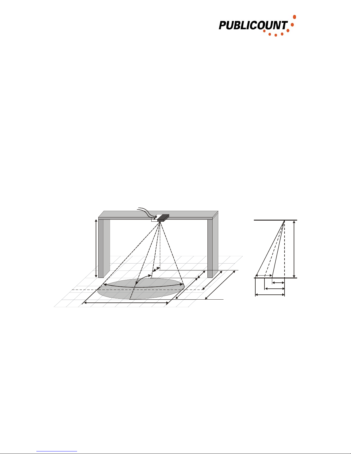
2.1. The size of the projection field
The following illustration shows the projection surface of the sensor field.
3°+9,5°
14°
27°
A
L
B
H
MEM
A
E
L
H
Fig. 2.1-1 Projection surface of the sensor
H = Sensor installation height
A = Beginning of sensor field
L = Length of sensor field
E = End of sensor field
M = Distance to the centre of the sensor field
Operating Instructions HUZ3 6 / 6
2. Sensor installation
The size of the projection field is calculated as follows:
A
E
L
H
HE
H
HM
H
HA
−=
=°=
=°=
=°=
2
)5.26tan(
8.2
)5.19tan(
5.4
)5.12tan(
B = Width of sensor field
9.3
)5.13tan(
)5.19cos(2
HHB =°
°
=
People are counted as they cross the centre line (distance M).
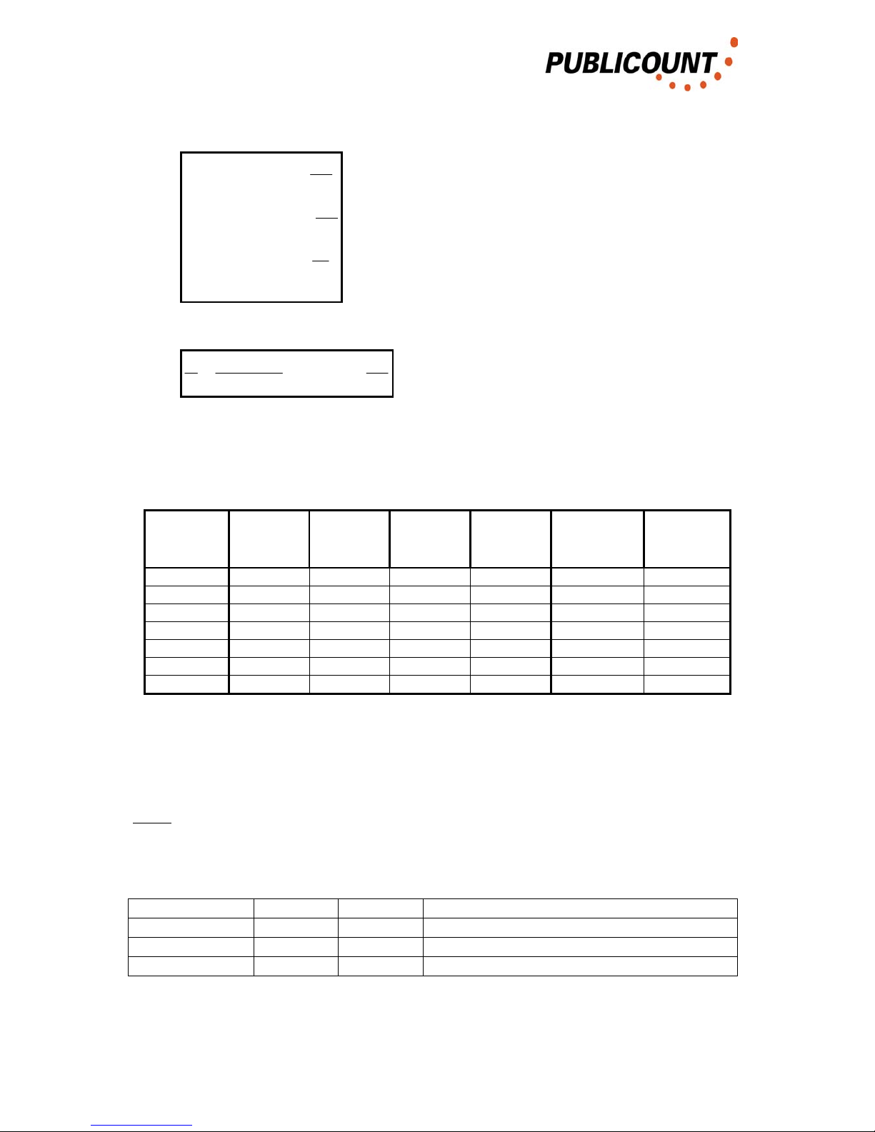
The following table shows the parameters of the projection field for different
installation heights:
H / m
Height
A / m
Beginning
M / m
Centre
E / m
End
L / m
Length
Bfloor / m
Width on
the floor
(B1m/2) / m
Width at
1m height
2.8 0.62 0.99 1.40 0.78 1.42 0.92
3 0.67 1.06 1.50 0.83 1.52 1.01
3.2 0.71 1.13 1.60 0.89 1.64 1.12
3.4 0.75 1.20 1.70 0.94 1.74 1.22
3.6 0.80 1.27 1.79 1.00 1.84 1.32
3.8 0.84 1.35 1.89 1.05 1.94 1.42
4 0.89 1.42 1.99 1.11 2.04 1.52
Size of the sensor field for different installation heights
It should be noted that these parameters do not represent definite lines (the
projection field is simply weaker here).
Note:
The parameters given above refer to an intensity drop of 3 dB. The following angles
apply for other intensity levels:
Intensity drop Width (B) End (E)
3dB 27° 26.5° Innocent specification
5dB 38° (23+3)° From directional characteristic
10dB 64° (30+3)° From directional characteristic
Operating Instructions HUZ3 7 / 7

2. Sensor installation
2.2. Number of sensors to be installed
The number of sensors to be installed depends on the firmware version of SMC
used.
2.2.1. SMC Firmware 1.x
The number of sensors to be installed depends on the installation height and the
width of the section to be covered.
The distance between the sensors is installation height / 3. The distance between
the wall and the outside sensors is installation height / 6.
h
h/3 h/3 h/3 h/6
h/6
SMC
1 2 3 4
Fig. 2.2.1-1 Distance between sensors
There should be a deviation of no more than 5% from this parameter.
Operating Instructions HUZ3 8 / 8

2. Sensor installation
2.3. Position of the projection field
For correct operation, the sensors must be projected in such a way that
• there are no moving parts within the sensor field, such as:
o entrance doors which swing through the sensor field
exception: glass doors without metal gridding
o escalators, fans
• there are no people present in the sensor field for long periods, e.g.
o if there are goods located within the sensor field which the customer
walks around a number of times and so is counted more than once
o if queues form here.
• the construction on which the sensors are mounted is vibration-free.
In addition the following points must be taken into account with respect to the position
of the projection field:
• If the projection field lies too far inside the shop there is the likelihood that
people will remain within the projection field for a considerably longer time
(they come in and then think first of all about where they want to go / goods
displays in the vicinity of the entrance area / ...).
• If the projection field lies too far out it is possible for people to be counted who
have not entered the shop (looking in from outside and then going away again
/ walking outside along the line of the sensor field / ...)
• If the entire entrance area is not covered, then people can walk in such a way
that they do not cross the counting area (see Fig. 2.3-1)
• The projection field should not be directed at metal flooring elements (if the
store is in the construction phase, mats can be used which do not contain any
metals)
Getting the projection right is crucial for later adjustment. If the projection is poorly set
up, a counting accuracy of 95% can only be achieved with a very great deal of
adjustment, or possibly not at all.
If the client wishes the sensors to be positioned differently (e.g. for optical
reasons), it must be pointed out that this means that a counting accuracy of
95% can no longer be guaranteed.
A few examples of the position of the projection field are given on the next page.
Operating Instructions HUZ3 9 / 9

2. Sensor installation
The following illustration shows the entrance of a store (the dark rectangles represent
the wall where the entrance ends). For counting to be correct, the projection fields
must be arranged to that their centre line covers the entire entrance area.
Inside
Outside
Projection fields
Fig. 2.3-1 Position of projection fields at the entrance
All sensors in this entrance area are to be given the same entrance number in the
configuration assignment (e.g. all entrance 1).
In the following illustration, the entire entrance area is not covered, which means that
people can walk in such a way that they do not cross the counting area.
Inside
Outside
Projection fields
Path f a person, that does not
cross the sensor fields
Fig. 2.3-2 Position of projection fields at the entrance – Poor projection
If the entrance is divided by a pillar, for example, as shown in the following
illustration, then the sensors are assigned to the different entrances.
Inside
Outside
Entrance 1 Entrance 2
Fig. 2.2-3 Position of projection fields in an entrance with pillar
[Innen = Inside, Aussen = Outside, Eingang = Entrance]
Operating Instructions HUZ3 10 / 10
2. Sensor installation
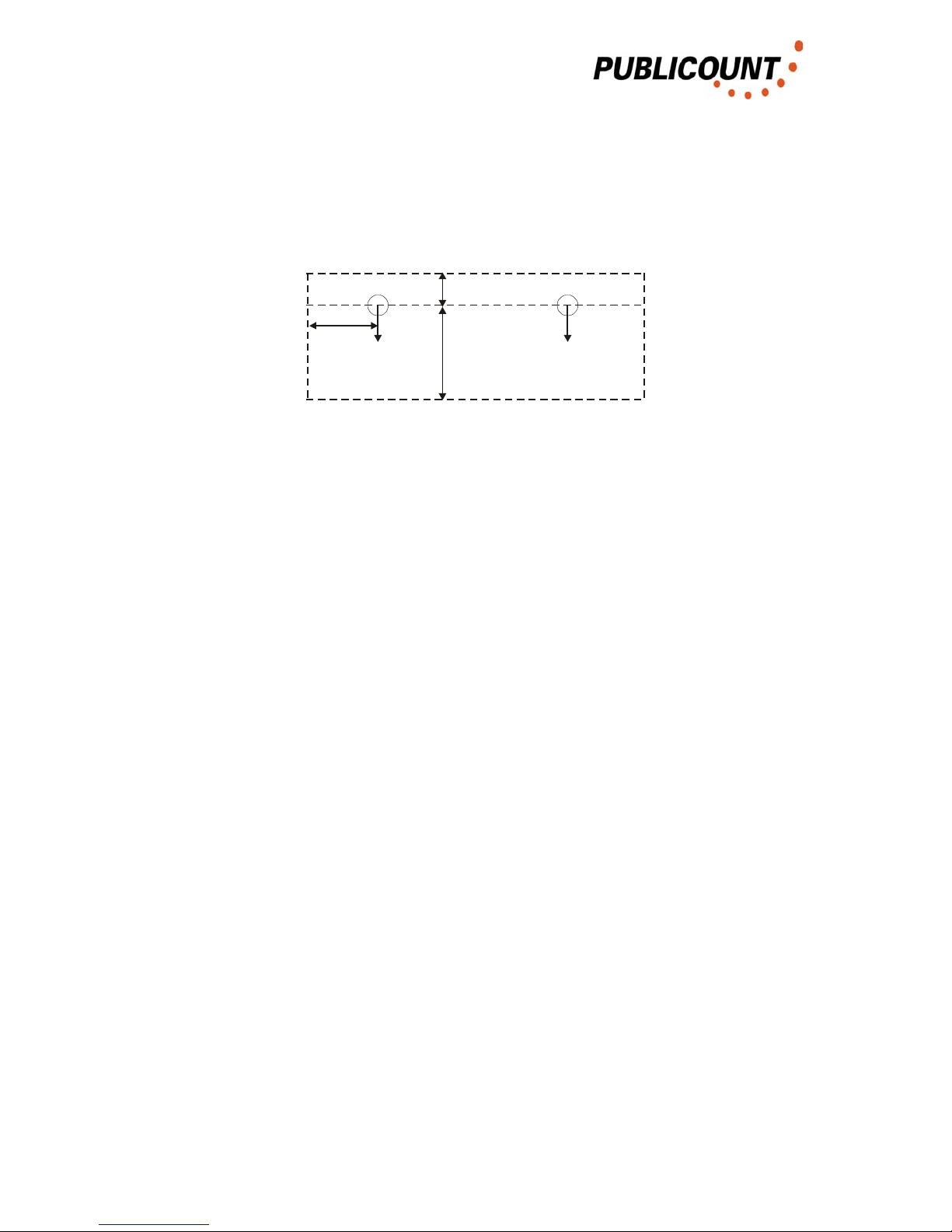
2.4. Floor markings
With some installations, floor markings are applied which mark the area where no
goods should be displayed to the customer. The following illustration shows the area
which must be kept free:
0,5*H + 0,5m
1,5m
0,5m
Fig. 2.4-1 Area which must be kept free for accurate counting
The markings are applied at the corners of the free area in each case.
Operating Instructions HUZ3 11 / 11

2. Sensor installation
2.5. Connector assignment
Each sensor is connected to the SMC via a 6-core, flexible shielded ............ cable.
A shielded 8-pin RJ45 connector is used on the SMC side and an unshielded 6-pin
RJ45 connector is used on the sensor side. The shielding is applied on one side of
the SMC.
Warning: If the shielding is applied to both sides, this may result in damage
to the sensor.
8
16
1
Fig. 2.5-1 RJ45 connector, 8-pin / 6-pin
Connector assignment:
RJ45 – 8-pin SMC Sensor RJ45 – 6-pin
1 Shielding
2 Gnd Gnd 1
3 Gnd Gnd 2
4 RS485 – B RS485 – B 3
5 RS485 – A RS485 – A 4
6 U+ U+ 5
7 U+ U+ 6
8 Shielding
The RJ-45 sockets of the SMC also have contact lugs for shielded RJ-45 connectors,
so that, as an alternative, the shielding can also be applied to the connector housing
instead of pin 1 and pin 8.
The LEDs on the RJ-45 sockets of the SMC come on when a data transfer with a
sensor occurs on the corresponding port or this is attempted on the part of the SMC.
Operating Instructions HUZ3 12 / 12

2. Sensor installation
2.6. Connection of sensors to the SMC
The sensors have a star connection with the SMC.
In order to simplify servicing the sensors are numbered as follows:
Outside
Inside
1 2 3 4
Fig. 2.6-1 Numbering of sensors
Looking into the shop from outside, the sensors are numbered from left to right.
Operating Instructions HUZ3 13 / 13

3. Connecting MSPs together
3. Connecting SMCs together
If a number of SMCs are required in order to cover all the entrances and/or access
ways in a store, these are to be connected via the RS485 data bus in a ring line open
on one side.
Cable ................ is used, as with the connection of the sensors.
The shielding is connected on one side of the cable with the shielding of the modular
connector.
Warning: Applying shielding to both sides may result in communication
errors and, with the HUZ2(b), also to damage to this.
8
1
Fig. 3-1. RJ45 connector, 8-pin
Connector assignment:
RJ45 – 8-pin SMC
1
2
3
4 RS485 – B
5 RS485 – A
6
7
8
Operating Instructions HUZ3 14 / 14

4. PC, Modem, Com Server
4. PC, Modem, Com Server
Results are displayed and counting data are stored long-term on a PC. For this
purpose, PUBLICOUNT GmbH offers Publicount Soft and Publicount View software.
The RS485- Ports of the SMC are supposed for the data request. The RS232- Ports
are supposed for User Configuration of the SMC, maybe with use of a Bluetooth-
Module. So the SMC initialises a Bluetooth Module after Power On. A Modem
connected to RS232 will loose its Configuration in case of this initialisation.
4.1. End equipment connected to the RS232 port of a single SMC
This option should only be considered for small units with just one SMC and a
maximum line length of 20 m between SMC and PC.
For this, the SMC must be also positioned next to the end equipment.
Option 1: PC and SMC are connected via a standard zero modem cable. The
data connection to the SMC is via the RS232 port. An additional 230 V
connection must be available for the PC.
Option 2: Ethernet server and SMC are connected with a standard zero modem
cable. The data connection to the SMC is via the RS232 port. An
additional 230 V connection and the Ethernet connection / modular
RJ45 must be available for the server. Both connections to the Ethernet
server are plug connections.
Option 3: Modem and SMC are connected over a RS485 Converter. The data
connection to the SMC is via the RS485 port. An additional 230 V
connection and an analogue telephone connection must be available for
the modem. Both connections to the modem are plug connections.
SMCModem RS232 / RS485
Converter
RS485RS232
Fig. 4.1-1. Modem connected to SMC
Operating Instructions HUZ3 15 / 15

4. PC, Modem, Com Server
4.2. End equipment connected with the RS485 bus for more than
one SMC
This option must be adopted when a number of SMCs are used.
For the sensors, cable .......... should be run from a free bus connection on the first
SMC to the end equipment in position.
The bus is connected to the RS485 converter in the usual way here.
The RS485 converter has a 9-pin SUB-D plug as its RS232 data connection. The
end equipment is connected to it as already described in the previous section.
SMC
Adr. 1
RS232 / RS485
Converter
SMC
Adr. 2
SMC
Adr. n
End
Equipment
RS485RS232
Fig. 4.2-1. End equipment connected to more than one SMC
The RS485 converter does not need its own 230V connection. Power is supplied to it
from the connected SMC and for this reason the bus line between SMC and
converter must be a 4-core line (connector arrangement the same as the connection
lines between SMC and sensors). Cable shielding is provided on both sides.
Operating Instructions HUZ3 16 / 16

5. Operating the SMC
5. Operating the SMC
A terminal programme is required for operating the SMC.
The connection between PC and SMC can be produced via a zero modem cable to
its RS232 interface or, optionally via Bluetooth.
With Bluetooth, the stages described in Appendix A4 must be followed in order to
make a connection.
5.1. Terminal settings
The HyperTerminal supplied with Windows, for example, is suitable as the terminal
programme. This is found under
Start – Program Files – Accessories– Communication - HyperTerminal
The settings are:
Baud rate 9600
Data bits 8
Parity none
Stop bits 1
Flow control none
In addition, under
Start – Setting – System control - Keyboard
the delay must be set to short and the repeat rate to high.
Operating Instructions HUZ3 17 / 17

5. Operating the SMC
Operating Instructions HUZ3 18 / 18

5. Operating the SMC
5.2. General operation
The following commands function independently of the SMC firmware and SMC
being used. In contrast to the HUZ2, the two ports (RS232, PC) are separate in the
SMC, i.e. there are no outputs over RS485 during the configuration of the SMC via
RS232. Therefore data may be called up by the PC over RS485 parallel to
configuration.
5.2.1. Interrogation into SMCs connected
If key 'a' is depressed for 2-3 seconds, the connected SMC responds with the
message
HUZ3 Version 1.1 = PCHUZ91 English - Address 1
This gives the firmware version, language and address of the SMC. The address is
set to 1 at the factory.
In the example Firmware version 1.1 = PCHUZ91 (emulated version)
Language English
Address 1
If a number of SMCs are connected to the RS485 bus, this cannot be interrogated
with 'a'.
5.2.2. Activating the SMC
The SMC is activated as follows:
1. Hold key '0' down for 2 - 3 seconds
2. Enter the address of the SMC (e.g. 1 for address 1)
3. Confirm input with Enter
The response by the SMC contains additional operational options, e.g. start a control
count.
Operating Instructions HUZ3 19 / 19

5. Operating the MSP3 – Firmware 1.x
5.3. Firmware 1.x
Firmware version 1.x represents the replacement firmware for HUZ2 versions 60, 61,
90 and 91.
For operation the sensor versions RN-SE2, KF or KF32.x are required.
All points of the HUZ2 firmware are contained in this, under other names. In contrast
to the HUZ2 versions, the SMC differs in the following points:
- in-counts / - people / ... renamed as „Counts in“ / "Person in“ / ...
- out-counts / - people / ... renamed as "Counts Out“ / Person out“ / ...
- The "Demo Modus“ has been renamed "Control Counting“ and is selected
using key 'c’. As up to 12 inputs are possible, the entrances to be displayed
can be selected by key 'd' (Display Entrance).
- The "Test Modus“ has been renamed "Live Mode“ and is activated with key 'l'.
- "Basic settings" and "Assignment" have been brought together in a
configuration menu which is opened with key 'c' (Configuration Menu). This
menu also displays the firmware version of the sensors. The operation of this
menu is described below.
- The SMC has a Bootloader, by means of which it is possible to update the
SMC firmware.
- All parameter inputs (e.g. address) can be interrupted with ENTER or ESC.
The following remain the same:
- Connected SMCs are interrogated with key 'a':
- Activate the SMC by keeping key '0' depressed (approx. 2 seconds), then
enter the SMC address and confirm with ENTER.
- Auto-test is still selected using key 's'. All data stored are lost with the auto-
test.
In the text below there is first a description of the setting parameters of SMC version
1.x, with their meanings. Then the operation of the SMC is described.
Operating Instructions HUZ3 20 / 20
Table of contents


