Pullman Holt MAGNETspray User manual

OWNER’S MANUAL
FOR THE
MAGNETspray
Pullman-Holt Corporation
Main Office: 10702 North 46th Street Tampa, FL. 33617
Phone: (813) 971-2223 · FAX: (813) 971-6090

Operation Guide
To Operate:
1
Prepare the tank mix.
2
Connect the twinline hose to the front panel.
3
Connect the twinline hose to the liquid and air leaders on the
handgun. If using the plastic bottle, connect the grey hose of the
plastic bottle hose assembly instead of the solution hose of the
twinline hose to the liquid leader.
4
Plug the power cord into an appropriate receptacle. Turn on the
air compressor.
5
Engage the trigger and spray.
To clean the sprayer after operation:
1
Clean the exterior of the sprayer.
2
Clean the tank and/or the plastic bottles
3
Disconnect the twinline hose from the handgun air line and liquid
line leaders.
4
Disassemble and clean the liquid filter. Be careful not to lose the
flow disk
5
Unthread the quick connect plug from the handgun liquid line
leader. Use a 7/16” wrench on the plug and an 11/16” wrench on
the 1/8” NPT body.
6
Connect the quick connect plug to the grey hose of the twinline
hose.
7
Fill the tank with 2 gallons of clean water.
8
Turn on the air compressor to flush the line with 1.75 gallons of
water. Turn off the air compressor.
9
Disconnect the quick connect plug from the twinline hose. Re-
thread it into the handgun liquid line leader.
10
Reassemble the liquid filter.
11
Turn on the air compressor and engage the trigger to flush the
handgun lines with the remaining water. Check the nozzles for a
good spray pattern while flushing. Allow air to flow for 30 seconds
after the water has been sprayed.
12
Apply silicone spray or similar lubricating oil to all quick connect
fittings.
13
Record application in the Spray Log.


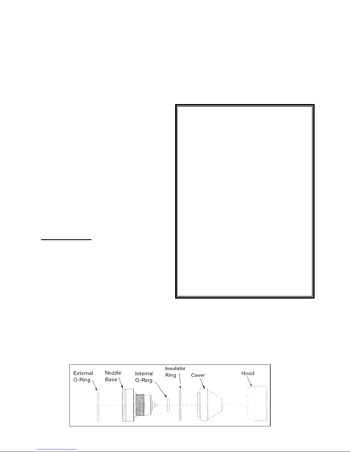
The Nozzle Assembly
The nozzle assembly is located at the end of
the handgun wand. It is composed of a
nozzle base, internal o-ring, Teflon ring,
cover, external o-ring, and a hood (see
Diagram 5). To access nozzle components,
just unscrew the nozzle cover by hand.
In order to optimize nozzle life and achieve
maximum spray efficiency, the nozzle must
be properly maintained. Always rinse the
handgun out with clean soapy water after
every spray, and establish maintenance
intervals to disassemble and clean the
nozzle. You may wish to purchase tank
cleaner, which cuts hard water scale and
chemical deposits from the electrode and
internal component of the gun. Your nozzle
maintenance schedule will vary depending on
the types of chemicals used and adherence
to pre and post spray checks, In general it is
sufficient to thoroughly clean nozzles every
50 hours. If heavy loads of wettable powers
are used, the cleaning schedule should be
sooner.
Pre-Spray Check
I. Inspect Nozzles
Check nozzle cover to make sure it is on
hand tight (do not over tighten or use a
wrench). Make sure the hood is seated firmly
to the nozzle base and against the external o-
ring.
II. Preparing the Tank Mix
If you will be spraying wettable powders it is a
good idea to use a compatibility agent with
the water and tank mix. Compatibility agents
are chemicals mixed with the water that make
mixing easier and keep heavy concentrations
uniformly in suspension.
Post-Spray Check
After each spray it is essential that hoses and
handgun be flushed with clean soapy water.
This will help prevent chemical build-up that
can clog lines and nozzles. Also, it is
recommended that the nozzle exterior (black
portion of nozzle) and nozzle hoods be
cleaned with soapy water at this time.
To clean the nozzle assembly:
1. Slide the hood over the nozzle cover.
2. Unscrew the cover from the nozzle base
and remove the Teflon ring. Note: There
is a small o-ring in the nozzle around the
base of the tip, take care that it doesn’t
fall off. If it does, clean it and press back
into place. Also, take care not to damage
the nozzle tip when the cover is removed.
3. Soak the ring, cover, and hood in a mild
detergent solution. Use a small brush
(soft or mild bristle) to clean the inside of
the cover and the hole through it. Also,
be sure to clean the hood. Rinse.
4. Scrub the nozzle base with the detergent
solution using a soft bristle brush. Be
sure to thoroughly clean the base cavity
and take care not to damage the nozzle
tip. Rinse and make sure the small o-ring
is in place.
5. Reassemble nozzle by placing the Teflon
ring on the base and screwing the cover
on hand tight. Next, slide the hood over
the nozzle and seat it securely against the
external o-ring.
Diagram 4: The Nozzle Assembly

The Air & Liquid Delivery System
The Air Compressor
The air compressor produces compressed
air which atomizes and propels the liquid. It
plugs into a 110 volt electrical source. Use
the unit with an extension cord of no more
than 50 feet and rated for no less than 15
amp service. The On/Off switch is on the
side of the air compressor. The compressor
has an adjustable relief valve on the back.
It should be set between 70 and 100 psi.
The Front Panel Air Connection
The second tee routes the air to the top ¼”
female ball swivel (FBS) fitting on the front
panel of the sprayer. The ¼” end of the air
hose of the twinline hose connects to this
fitting. Use an 11/16” wrench on the FBS
and 9/16” wrench on the twinline hose
fitting. The other end of the twinline hose
connects to the air leader of the handgun.
The Tank Pressure Regulator
The second tee also routes air to the tank
pressure regulator. It corresponds with the
pressure gauge on the left side of the front
panel. The regulator is operated by pulling
out the dial and turning it clockwise to
increase pressure or counter-clockwise to
decrease pressure. It should be set
between 12 and 15 psi. Once the desired
pressure is achieved, push in the dial to lock
it in place.
Note: For best results, set the pressure
from a lower pressure to a higher pressure.
If the pressure is set too high, adjust the
regulator below the desired pressure then
adjust it up to the desired pressure.
Two lines run from the tank pressure
regulator. One line runs to the tank
pressure gauge on the front panel. The
other runs to the inlet quick connect on the
tank.
Figure 2. The Air and Liquid Delivery Systems
To disconnect the quick connects:
1. Slide the sleeve on the quick
connect socket up.
2. While holding the sleeve up, pull the
socket off the quick connect plug.
To connect the quick connects:
1. Slide the sleeve of the quick connect
socket up.
2. While holding the sleeve up, push
the socket onto the quick connect
plug.
3. Release the sleeve.
4. Pull on the socket body to ensure
that it is properly seated and cannot
be pulled off the plug when the
sleeve is down.
To open the tank:
1. Push up the lever on the tank lid so
it is vertical. This depressurizes the
tank.
2. Pull the handle of the tank lid up.
3. Holding on to the handle, rotate the
tank lid 90° clockwise.
4. Pull out the tank lid. Notice the
direction of the tank lid in
relationship to the tank opening.
To close the tank:
1. Slide the lid into the tank opening,
using the same direction as when it
was removed.
2. Rotate the lid 90° counterclockwise.
3. While pulling the lid up to seal it
against the tank opening, push
down on the lid handle until it is
parallel with the tank lid.
4. Push the pressure valve lever down
so it is horizontal.
The Quick Connects
There are four sets of quick connects (plug
and socket) on the sprayer: tank inlet, tank
outlet, handgun liquid inlet, and handgun air
inlet.
The Tank
The tank should be thoroughly cleaned
immediately after each use by triple-rinsing
the tank; a commercially available tank
cleaner may be used and is recommended
when the unit is used to spray wettable
powders on a regular basis.
Note: Do not operate the sprayer when the
tank lid is not securely closed. Tank
agitation is powerful and liquid may splash
out if the lid is not closed.
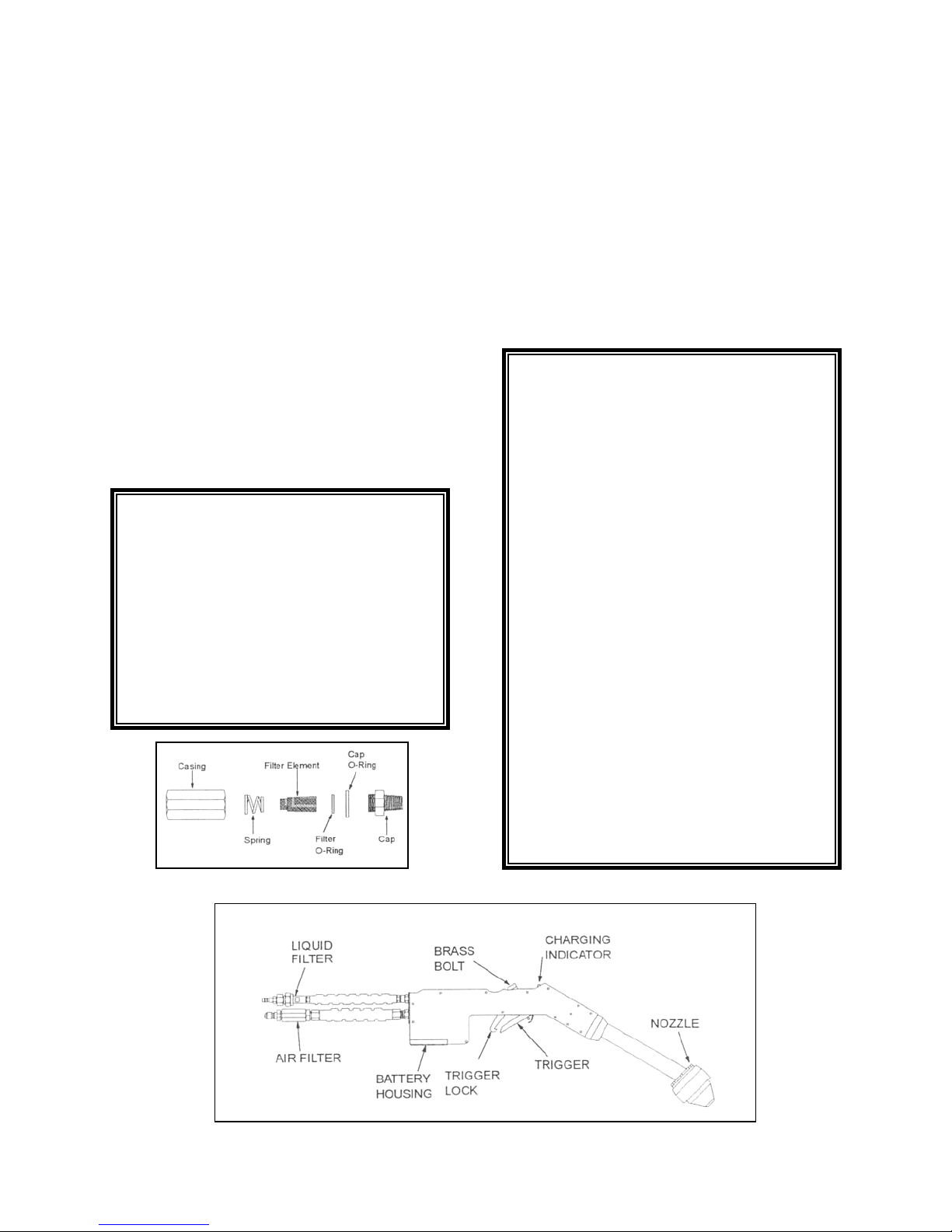
To clean the air filter:
1. Unthread the casing from the cap
using a ¾” wrench on both parts.
Be careful not to lose the spring or
the air filter inside of the casing.
2. Check inside each part for debris.
Clean any dirt out with compressed
air or warm, soapy water.
3. Reassemble the air filter, making
sure to put it together as in Diagram
2.
To engage/disengage the trigger:
1. Pull the trigger up towards the body
of the handgun to start spraying.
2. To keep spraying, either keep
holding the trigger or lock it in place
by pulling up the lock and hooking
the trigger.
3. To stop spraying when the trigger is
not locked, let go of the trigger.
To clean the trigger:
1. Unthread the brass bolt on the top of
the handgun with a 5/8” socket
wrench. Be careful not to lose the
spring, plunger, copper washer, and
small brass bushing inside the
trigger. Note how they fit inside so
they may be replaced properly.
2. Check inside the trigger for
blockage. Clean out any debris with
compressed air or warm, soapy
water.
3. Replace the spring and plunger;
rethread the brass bolt into the top
of the handgun until tight.
The Handgun
The handgun is held by the operator during
spraying. Activation of the trigger causes
liquid to spray. The handgun has the
following user-serviceable parts: the air
filter, the liquid filter assembly, the nozzle
assembly, and the batteries. Except for the
batteries, which are accessed by removing
the battery cover, nothing inside the
handgun shell is user-serviceable. Do not
open the handgun shell; doing so will void
the warranty on the handgun.
The Air Filter
The air filter is located outside the base of
the handgun in the air hose. It filters dirt out
of the air lines. There is an extra air filter in
the bag which is stapled to this manual in
case the original is lost or damaged.
The Trigger
The trigger turns the spray on and off. It
can be continuously held for operation or it
can be locked in place. When it is on, the
charging indicator on the top of the handgun
shell glows red to indicate that the nozzles
are charging.
Diagram 1. The Handgun
Diagram 2. The Air Filter

To change the batteries:
1. Unscrew the 2 6-32 x ½” phillips
head machine screws which hold
the battery cover in place.
2. While holding the leads in one hand,
gently disconnect the batteries from
the leads. Be careful not to tear the
leads off the wires or the tear the
lead wires out of the power supply.
3. Connect 2 fresh 9 volt batteries to
the leads.
4. Replace the battery cover. Screw
the 2 6-32 x ½” Phillips head
machine screws back in to secure
the battery cover.
The Batteries
The nozzle charging operates on two 9 volt
rechargeable batteries which are located in
the base of the handgun. In average
conditions, the batteries will last 5-10 hours
of operation on a charge. They should be
recharged when the charging indicator on
top of the handgun shell doesn’t glow when
the trigger is engaged during operation.
After a while the batteries will wear out and
need to be changed. Replace with Nickel-
Hydride rechargeable batteries.
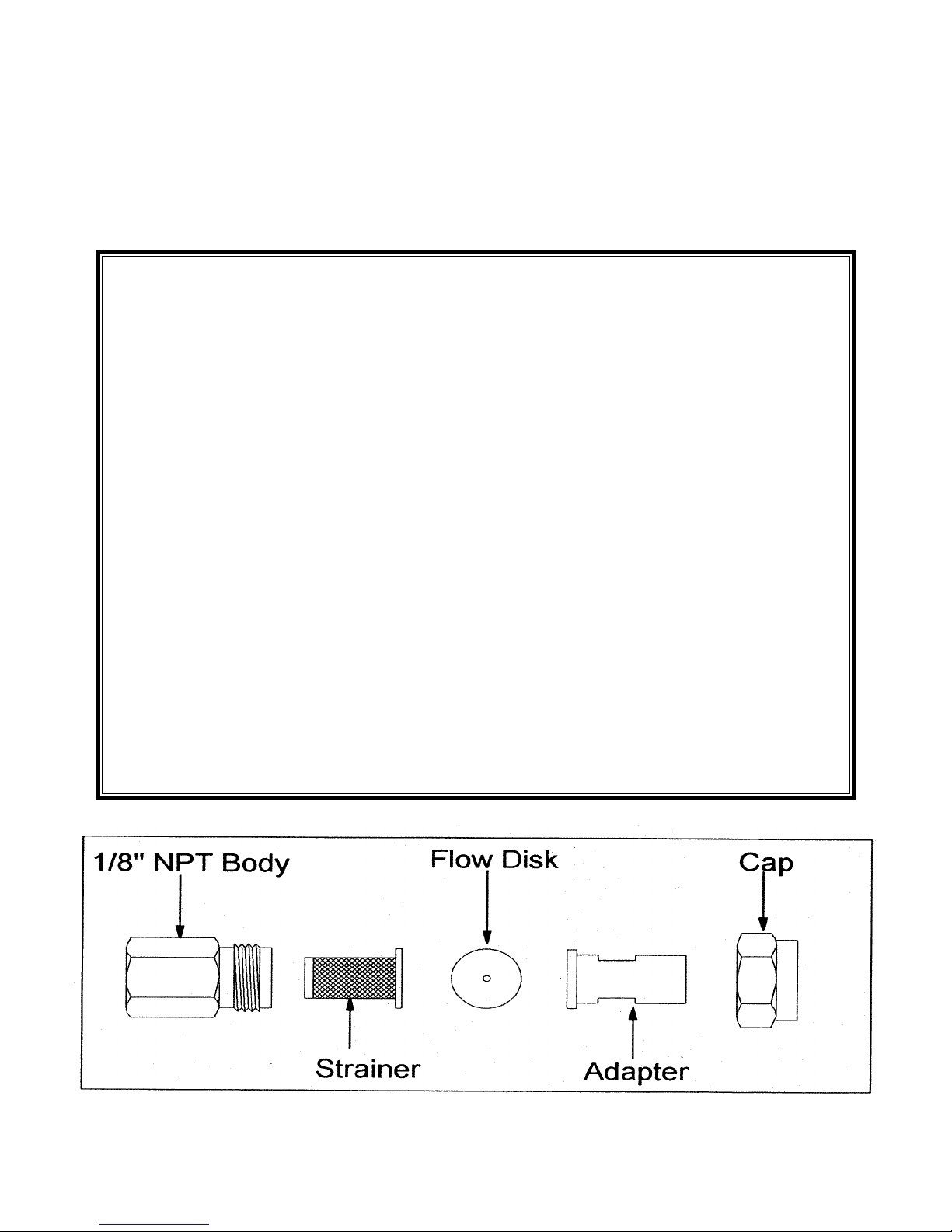
The Liquid Filter Assembly
The liquid filter assemby is located
outside the base of the handgun. It
is composed of these parts: a 1/8”
NPT body (item 10), a strainer (item
11), and a cap (item 12). The
strainer is the active filtering element
in the volume of liquid that flows
through the line. There is an extra
flow disk and an extra strainer in the
bag which is stapled to this manual
in case the originals are lost or
damaged.
To disassemble, clean and reassemble the liquid filter assembly:
1. Using a 13/16” wrench on the cap and and 11/16” wrench on the 1/8” NPT body,
unthread them.
Note: When you disassemble the liquid filter assembly, notice how the parts fit
together in order to reassemble them properly. Be careful not to lose any parts,
particularly the flow disk which is inside the cap. The sprayer will not function
correctly without the flow disk.
2. Remove the strainer from the 1/8” NPT body.
3. If the 1/8” NPT body contains residue, clean it with compressed air or clean
water.
4. Clean the strainer with compressed air or clean water. If residue still remains in
the 50 mesh screen, disassemble the Strainer. Unscrew the top brass part from
the bottom brass part. The 50 mesh screen slides off the brass body and can be
cleaned with compressed air or clean water. If residue still remains, soak the 50
mesh strainer in water. If necessary, scrub it with a soft toothbrush to remove
stubborn residue. Replace the 50 mesh screen and screw the top brass part
back on the lower brass part.
5. If the flow disk is still in the cap, remove it. Check the aperture of the flow disk for
blockage. If there is any, clean it with compressed air or clean water. Replace
the flow disk so that the numbers on the disk face the strainer.
6. Replace the strainer in the 1/8” NPT body.
7. Rethread the 1/8” NPT body and the cap.
Diagram 3: The Liquid Filter Assembly

TROUBLE-SHOOTING GUIDE
Problem: Air pressure of spray appears low:
1. Clean the liquid filter assembly. See “The Liquid Filter Assembly”.
2. Make sure that the liquid filter assembly is installed correctly. See Diagram 3 on p. 12.
3. Make sure that the air filter is installed correctly. See Diagram 2 on p. 11.
4. Clean the air filter. See “The Air Filter”.
5. Clean the trigger. See “To Clean the Trigger”.
Problem: No spray comes out of the nozzle or spray is erratic:
1. Make sure that the air pressure regulator is set between 12-15 psi.
2. Make sure that water temperature is at least 50° (10°C).
3. Make sure that all liquid fittings and air fittings are tight.
4. Clean the liquid filter assembly. See “The Liquid Filter Assembly”
5. Clean the nozzle assembly. See “The Nozzle Assembly”.
6. Clean the trigger. See “To Clean the Trigger:.
Problem: Charging indicator blinks or goes out during operation:
1. Change the batteries. See “The Batteries”.
2. Clean the Nozzle. See “The Nozzle Assembly”.
Problem: Air compressor will not start:
1. Make sure that the electrical cord is plugged in an appropriate receptacle.
2. Make sure that the switch on the side of the air compressor is on.

TANK PLUMBING ASSEMBLY
XT SERVICE PARTS
MAIN ASSEMBLY

Unlike conventional sprayers, your sprayer
uses a different method for chemical
application. Therefore, new techniques must
be used to spray and new formulas
developed to properly prepare tank mix. This
section will discuss proper spray techniques
and how to prepare a tank mix.
Note: When using unfamiliar equipment or
chemicals, always test on a small area before
treating the entire crop. Do not use a
chemical with the sprayer if the label
prohibits use in low-volume sprayers.
at full rate, you can start reducing the amount
of chemical used for each spray. Keeping the
amount of water in the tank constant, cut the
amount of chemical mixed in by 15-25% for
each spray until a desirable kill is no longer
achieved. If you are planning to cut rates
then it is very important to scout your crop to
determine spray efficiency.


HANDGUN SERVICE
PARTS

Other manuals for MAGNETspray
1
Table of contents
Other Pullman Holt Paint Sprayer manuals


