manuals.online logo
Brands
  1. Home
  2. •
  3. Brands
  4. •
  5. Carlisle
  6. •
  7. Paint Sprayer
  8. •
  9. Carlisle DeVIBISS JCK User manual

Carlisle DeVIBISS JCK User manual

1
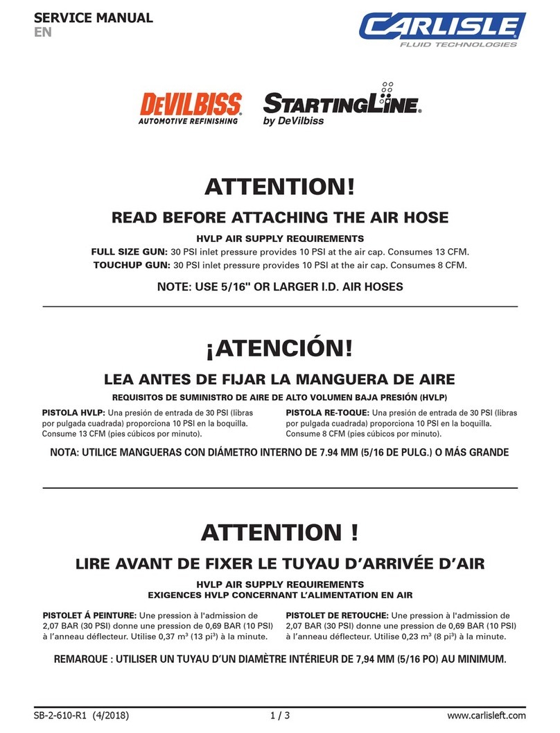
Important: Read and follow all instructions and WARNING before using this equipment.
JCK ―Air Cap ―Fluid Tip and Type of Feed (G: Gravity
,
S: Suction, P: Pressure)
(Ex.): JCK
-
LV2
-
13P
← (JCK
-
LV2 Air Cap
-
Fluid Tip I.D. 1.3mm, Pressure Feed)
SPECIFICATIONS
MaximumWorkingAirPressure
:
0.69MPa
MaximumWorkingFluidPressure
:
0.69MPa
Fluid Inlet
:
G1/4
Air Inlet
:
G1/4
Chart. 1
Painting Conditions: Air Inlet Regulator = HARG-510 Paint Viscosity = 20sec
★
13sec (IHS) Spray Distance = 200mm
Type of Feed
Air Cap Name
Part No.
Fluid Tip I.D.
(mm)
Air Inlet Pressure
(MPa)
Air Consumption
(ℓ/min)
Fluid Output
(mℓ /min)
Fan Pattern Size
(mm)
Gun Weight
(g)
Gravity
SS1
( )
0.8
0.1
80
★50
★120
290
SS3
( )
1.3
0.24
145
160
170
1.5
200
180
1.8
250
190
ST1
( )
1.0
0.2
240
★100
★220
1.3
135
240
1.5
165
1.8
200
Suction
SS3
( )
1.3
0.24
145
120
130
1.5
160
150
1.8
185
180
ST1
( )
1.3
0.2
240
95
180
1.5
115
190
1.8
140
210
Pressure
CN1
( )
0.8/1.0/
1.3/1.5
0.24
220
100
160
200
210
300
260
LV1
( )
0.8/1.0/1.3
0.2
230
100
150
200
200
300
250
LV2
( )
0.8/1.0/1.3
0.2
230
100
200
200
270
300
320
PARTS LIST
Chart. 2
Ref No.
Part No.
Description
Qty
Ref No.
Part No.
Description
Qty
1
JCK-6
RETAINING RING ASSY
1
11
JCK-14-K5
NEEDLE SPRING
1
2
See Chart.1
AIR CAP
1
12
JCK-13
NEEDLE ADJUST SCREW
1
3
JCK-440-XX
FLUID TIP & NEEDLE
1
13
JCK-463
NEEDLE PACKING ASSY
1
4
JCK-7
BAFFLE ASSY
1
14
JCK-108
TRIGGER KIT
1
5
JUP-8-K5
BAFFLE GASKET
1
15
JCK-42
CHEATER VALVE ASSY
1
6
JCK-35
FLUID INLET KIT
1
16
JCK-30
AIR CONNECTOR
1
7
NOT FOR SALE
GUN BODY
1
8
JCK-44
PATTERN VALVE ASSY
1
9
JCK-443
AIR SEALS & AIR VALVE KIT
1
10
JCK-12
AIR VALVE BUSHING ASSY
1
Note) Ref No.5 and No.11 are sold in kit of 5
Ref No.2: ex. JCK-3-ST1
Ref No.3: ex. JCK-440-13 (Fluid Tip I.D. = 1.3mm)
ACCESSORIES
Chart. 3
*Sold separately
Ref No.
Part No.
Description
17
LUNA2-34
AIR SEAL INSERTION TOOL
-
JCK-100
REPAIR KIT
KR-470-2C
SUCTION CUP 700CC 1/4 BSP
KGL-400-FA-ST
GRAVITY CUP FREE-ANGLE 400ML
KG-400C
GRAVITY CUP W/STAND (400ML)
HAV-501-B
AIR ADJUSTING VALVE W/GAUGE
HAV-503-B
AIR ADJUSTING VALVE W/GAUGE
Note) JCK-100 contains * marked items in Fig. 1
JCK Operation Manual
Fig.1
2
In this part sheet, the words
WARNING
,
CAUTION
and
NOTE
are used to
emphasis important safety information as follows:
⚠
WARNING
⚠
CAUTION
NOTE
Hazards or unsafe practices which could
result in severe personal injury, death or
substantial property damage.
Hazards or unsafe practices which could
result in minor personal injury, product or
property damage.
Important installation, operation or
maintenance information.
⚠
WARNING
Read the following warnings before using this equipment.
SOLVENTS AND COATING MATERIALS. Can be
highly flammable or combustible when sprayed.
Always refer to the coating material supplier's
instructions and safety sheets before using this
equipment.
INSPECT THE EQUIPMENT DAILY. Inspect the
equipment for worn or broken parts on a daily basis.
Do not operate the equipment if you are uncertain
about its condition.
READ THE MANUAL. Before operating finishing
equipment, read and understand all safety, operation
and maintenance information provided in the operation
manual. Users must comply with all local and national
codes of practice and insurance company
requirements governing ventilation, fire precautions,
operation, and housekeeping of working areas.
EQUIPMENT MISUSE HAZARD. Equipment misuse
can cause the equipment to rupture, malfunction or
start unexpectedly and result in serious injury.
FIRE AND EXPLOSION HAZARD. Never use
1,1,1-Trichloroethane, Methylene Chloride, other
Halogenated Hydrocarbon solvents or fluids containing
such solvents in equipment with aluminum wetted
parts. Such use could result in a serious chemical
reaction, with the possibility of explosion. Consult your
fluid suppliers to ensure that the fluids being used are
compatible with aluminum parts.
GLOVES. Must be worn when spraying or cleaning
the equipment.
WEAR SAFETY GLASSES. Failure to wear safety
glasses with side shields could result in serious eye
injury or blindness.
STATIC CHARGE. Fluid may develop a static charge
that must be dissipated through proper grounding of
the equipment, objects to be sprayed and all other
electrically conductive objects in the dispensing area.
Improper grounding or sparks can cause a hazardous
condition and result in fire, explosion or electric shock
and other serious injury.
WEAR RESPIRATOR. The use of respiratory
protective equipment is recommended at all times.
The type of equipment must be compatible with the
material being sprayed.
TOXIC VAPOURS. When sprayed, certain materials
may be poisonous, create irritation, or are otherwise
harmful to health. Always read all labels, safety sheets
and follow any recommendations for the material
before spraying. If in doubt, contact your material
supplier.
NEVER MODIFY THE EQUIPMENT. Do not modify
the equipment unless the manufacturer provides
written approval.
LOCK OUT / TAG-OUT. Failure to de-energies,
disconnect, lock out and tag-out all power sources
before performing equipment maintenance could
cause serious injury or death.
PROJECTILE HAZARD. You may be injured by
venting liquids or gases that are released under
pressure or flying debris.
NOISE LEVELS. The A-weighted sound level of
pumping and spray equipment may exceed 85 dB(A)
depending on equipment settings. Actual noise levels
are available on request. It is recommended that ear
protection is worn at all times while equipment is in
use.
PRESSURE RELIEF PROCEDURE. Always follow
the pressure relief procedure in the equipment
instruction manual.
KNOW WHERE AND HOW TO SHUT OFF THE
EQUIPMENT IN CASE OF AN EMERGENCY.
HIGH PRESSURE CONSIDERATION. High pressure
can cause serious injury. Relieve all pressure before
servicing. Spray from the gun, hose leaks or ruptured
components can inject fluid into your body and cause
extremely serious injury.
OPERATOR TRAINING. All personnel must be
trained before operating finishing equipment.
IT IS THE RESPONSIBILITY OF THE EMPLOYER TO PROVIDE THIS INFORMATION TO THE OPERATOR OF THE EQUIPMENT.
3
PREVENTIVE MAINTENANCE
1.
Dailylubricationandcleaningarenecessarytomaintainthebestconditionofthegun.
2.
Toclean the gun body,wipe exterior with solvent or cleaning solution dampened cloth.
Do not immerse the gun in a solvent or cleaning solution as it may damage the gun or
cause painting problems.
3. After using the gun, remove the paint and then pass an appropriate solvent or cleaning
solution through the paint path to wash away any remaining paint.
4. Do not leave any solvent or cleaning solution in the paint path or paint cup. It may cause
corrosion or damage.
5.
The AIR CAP (2) can be immersed in solvent and brushed down for cleaning. If orifices
are clogged, use a toothpick to remove obstruction. Never use a steel wire or hard
instrument. Thiswilldamageaircapandresultinadistortedspraypattern.
6.
The following portions should be lubricated regularly (
➡
in Fig.2); Sliding points of
TRIGGER KIT(14), PATTERN VALVE ASSY (8), CHEATAR VALVE ASSY (15),
NEEDLE ADJUST SCREW (12), AIR VALVE (9-4), and NEEDLE (3-2).
◆
For lubrication, SSL-10 Gun Lube* is recommended. (*Sold separately, contains NO
silicones or petroleum distillates.)
◆
Do not lubricate to any portion where not instructed.
7.
When installing AIR CAP (2), make sure no foreign materials adhered on RETAINING
RING ASSY (1)andthreadofbodyandthenoilonedropofGunLubeSSL-10.(
⇒
inFig.2)
8.
Apply non-silicone grease lightly on NEEDLE SPRING (11) and AIR VALVE SPRING
(9-5). Do not apply too much grease as itmayclogtheairpassage.
REPLACEMENT OF PARTS
Before replacing gun parts, remove materials from the gun for cleaning. Then release the air pressure of the gun and remove all hoses
and paint containers.Perform the replacement work in a clean place and fix the gun properly. Usetheappropriatetoolsindicatedfor
replacementofparts.
After replacing the parts, check the gun that the replaced parts are functioning properly.
FLUID TIP & NEEDLE (3)
1.
LoosencompletelyPATTERNVALVEASSY(8)knobbyturningtheknobcounterclockwise.
2.
RemoveNEEDLE ADJUST SCREW (12)and NEEDLE SPRING (11)and then withdraw NEEDLE (3-2).
3.
RemoveRETAININGRING ASSY(1)andAIRCAP (2).
4.
RemoveFLUID TIP (3-1)by using 19mm wrench.
5.
Clean the seal surface on the GUN BODY side and tighten a new FLUID TIP with a torque wrench (recommended tightening torque:
8N-m).
6.
Insert a new NEEDLE and NEEDLE SPRING and install the NEEDLE ADJUST SCREW.
FLUID INLET (6), AIR CONNECTOR (16)
FLUID INLET KIT
(6) and AIR CONNECTOR (16) are fixed together by sealing material. Do not remove these parts unless necessary, as it
may cause damage.
PATTERN VALVE ASSY (8), CHEATER VALVE ASSY (15)
Disassembling and reassembling PATTERN VALVE ASSY (8) and CHEATER VALVE ASSY (15) by using 13mm wrench. When disassembling
and
reassembling
, turn the knobs
fully
counterclockwise
.
AIR SEALS & AIR VALVE KIT(9)
1.
Remove NEEDLE ADJUST SCREW (12) and NEEDLE SPRING (11) andthen withdraw NEEDLE (3-2).
2. Remove AIR VALVE BUSHING (10) by using 14mm wrench.
3.
WithdrawVALVESPRING (9-5), AIR VALVE(9-4).
4.
Withdraw VALVE SEAT (9-3). Make sure not to damage the seal surface on the GUN BODY side.
5.
Remove LOCK SCREW (9-2) by using 7mm hex wrench.
Make sure not to damage the seal surface on the GUN BODY side.
6.
Push the AIR SEAL(9-1) toward the back of the GUN BODY toremoveit.
7.
Remove the AIR SEAL (9-6) inside the AIR VALVE BUSHING. Make sure not to damage the seal surface on the AIR VALVE BUSHINGside.
◆
DonotreusetheremovedAIRSEALS & AIR VALVE KIT.
8.
Install the new AIR SEALS & AIR VALVE KIT carefully in the reverse procedure of removal.
◆
The optional part; AIR SEAL INSERTION TOOL (17) is recommended for inserting the AIR SEALS (9-1, 3, 6).
9.
Install the NEEDLE, NEEDLE SPRING and NEEDLE ADJUST SCREW.
NEEDLE PACKING ASSY (13)
1.
Remove NEEDLE ADJUST SCREW (12) and NEEDLE SPRING (11) andthen pull out NEEDLE (3-2).
2.
Remove NEEDLE PACKING ASSY (13) by using10mm wrench.
3. Install a new NEEDLE PACKING ASSY. Use a 10mm wrench to tighten it until it stops lightly first, and then tighten it about 1/16 turn.
4.
Install the NEEDLE, NEEDLE SPRING and NEEDLE ADJUST SCREW.
Fig.2
4
TROUBLESHOOTING
Problem
Cause
Correction
Will not spray
No air or material is supplied to the gun.
CHEATER VALVE ASSY (15) nob is not properly adjusted.
NEEDLE ADJUSTING SCREW (12) is not properly adjusted.
Check air and material lines.
Adjust accordingly.
Adjust accordingly.
Improper spray pattern
A, B: Material build-up on the AIR CAP (2) or FLUID TIP (3-1).
A, B: AIR CAP (2) or FLUID TIP (3-1) damaged.
C, D: Incorrect fluid delivery or viscosity.
C, D: Incorrect air pressure.
Clean the AIR CAP or FLUID TIP.
Replace.
Adjust fluid delivery and viscosity.
Adjust air pressure.
Intermittent or fluttering spray
Insufficient material in the cup or loose Connector.
Partially obstructed fluid passage or hose.
Loose FLUID TIP (3-1).
Material build-up on the seating on FLUID TIP (3-1) and GUN BODY (7).
Damaged FLUID TIP (3-1).
Fill material or tighten the Connector.
Clean or replace.
Tighten.
Clean.
Replace.
Fluid leaking from
NEEDLE PACKING ASSY (13)
Worn or damaged NEEDLE PACKING ASSY (13).
Worn or damaged NEEDLE (3-2).
Replace.
Replace.
Dripping from FLUID TIP (3-1)
Material build-up on the seating on FLUID TIP (3-1) and NEEDLE (3-2).
Worn or damaged FLUID TIP (3-1) or NEEDLE (3-2).
NEEDLE PACKING ASSY (13) and NEEDLE (3-2) are stuck together.
Loose NEEDLE ADJUST SCREW (12).
Clean.
Replace.
Clean and lubricate.
Adjust accordingly.
15-5, Fukuura 1-chome, kanazawa-ku, Yokohama, Kanagawa Japan 236-0004
TEL : +81-45-785-6434 FAX : +81-45-785-6517
http://www.carlisleft.co.jp
©2020 Carlisle Fluid Technologies
®DEVILBISS is a registered trademark of Carlisle Fluid Technologies.
JCK_E01_21.10

Other Carlisle Paint Sprayer manuals

Carlisle IS40 User manual

Carlisle

Carlisle IS40 User manual

Carlisle BINKS TROPHY Series User manual

Carlisle

Carlisle BINKS TROPHY Series User manual

Carlisle MS Elite A5 User manual

Carlisle

Carlisle MS Elite A5 User manual

Carlisle BINKS 603 User manual

Carlisle

Carlisle BINKS 603 User manual

Carlisle DeVilbiss JGA-510 User manual

Carlisle

Carlisle DeVilbiss JGA-510 User manual

Carlisle Ransburg RansFlex RFXi Series User manual

Carlisle

Carlisle Ransburg RansFlex RFXi Series User manual

Carlisle DeVILBISS AGMDPRO-102-HV30C-K User manual

Carlisle

Carlisle DeVILBISS AGMDPRO-102-HV30C-K User manual

Carlisle BINKS 80-295 User manual

Carlisle

Carlisle BINKS 80-295 User manual

Carlisle Binks AA1600M User manual

Carlisle

Carlisle Binks AA1600M User manual

Carlisle Binks 7N User manual

Carlisle

Carlisle Binks 7N User manual

Carlisle BINKS TROPHY AA 4400 User manual

Carlisle

Carlisle BINKS TROPHY AA 4400 User manual

Carlisle MS Elite M5 User manual

Carlisle

Carlisle MS Elite M5 User manual

Carlisle Vector R Series User manual

Carlisle

Carlisle Vector R Series User manual

Carlisle SLG-620 User manual

Carlisle

Carlisle SLG-620 User manual

Carlisle DeVilbiss Compact HVLP User manual

Carlisle

Carlisle DeVilbiss Compact HVLP User manual

Carlisle BINKS 0811-7500-1 User manual

Carlisle

Carlisle BINKS 0811-7500-1 User manual

Carlisle Ransburg 81545 User manual

Carlisle

Carlisle Ransburg 81545 User manual

Carlisle Binks AA4400M User manual

Carlisle

Carlisle Binks AA4400M User manual

Carlisle Binks TROPHY AA 1600 User manual

Carlisle

Carlisle Binks TROPHY AA 1600 User manual

Carlisle DeVilbiss PROLite Series User manual

Carlisle

Carlisle DeVilbiss PROLite Series User manual

Carlisle SLG-650 User manual

Carlisle

Carlisle SLG-650 User manual

Carlisle BINKS 6143-0901-3 User manual

Carlisle

Carlisle BINKS 6143-0901-3 User manual

Carlisle MS Series User manual

Carlisle

Carlisle MS Series User manual

Carlisle BINKS 115 User manual

Carlisle

Carlisle BINKS 115 User manual

Popular Paint Sprayer manuals by other brands

Fimco 3PT-200-8R-1225FX4 owner's manual

Fimco

Fimco 3PT-200-8R-1225FX4 owner's manual

Ribimex Rubiland Pila50 PRP500PER User and maintenance manual

Ribimex

Ribimex Rubiland Pila50 PRP500PER User and maintenance manual

Sealey MVMP01 instructions

Sealey

Sealey MVMP01 instructions

PLANET ECLIPSE EMEK 68CAL Workshop manual

PLANET ECLIPSE

PLANET ECLIPSE EMEK 68CAL Workshop manual

Griots Garage the boss user manual

Griots Garage

Griots Garage the boss user manual

Titan 2453769 Operation manual

Titan

Titan 2453769 Operation manual

Titan Tool 1140ix owner's manual

Titan Tool

Titan Tool 1140ix owner's manual

Gloria Hydronette li-on user manual

Gloria

Gloria Hydronette li-on user manual

Fimco BB-304 owner's manual

Fimco

Fimco BB-304 owner's manual

Sealey HVLP05 manual

Sealey

Sealey HVLP05 manual

WAGNER W 180 P Original instructions

WAGNER

WAGNER W 180 P Original instructions

Graco 16U287 Repair manual

Graco

Graco 16U287 Repair manual

Grizzly H3266 instruction sheet

Grizzly

Grizzly H3266 instruction sheet

Smithco Spray Star 1750D Parts & Service

Smithco

Smithco Spray Star 1750D Parts & Service

Croplands RSRL3-100RC REEL Operator's manual

Croplands

Croplands RSRL3-100RC REEL Operator's manual

Dino-Power DP-X5 Operation manual

Dino-Power

Dino-Power DP-X5 Operation manual

Smith S103E Setting up

Smith

Smith S103E Setting up

SprayCraft SP3512 instruction manual

SprayCraft

SprayCraft SP3512 instruction manual

manuals.online logo
manuals.online logoBrands
  • About & Mission
  • Contact us
  • Privacy Policy
  • Terms and Conditions

Copyright 2025 Manuals.Online. All Rights Reserved.