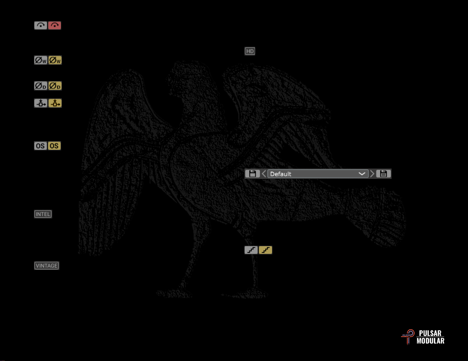
Delay on => –Option for changing the WET signal DELAY trim
pot from the default setting of WET to an alternate setting of DRY.
Setting this option to WET results in the WET signal DELAY trim
pot delaying the processed signal relative to the unprocessed
signal. Conversely, setting this option to DRY results in the WET
signal DELAY trim pot delaying the unprocessed signal relative to
the processed signal.
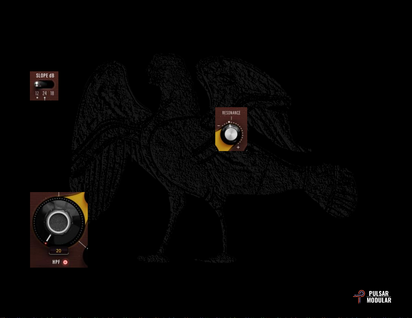
The HPF SLOPE dB selector sets the slope of the
cutoff frequency.
In addition to choosing the dB/oct slope, the SLOPE
selection will also affect the RESONANCE
characteristics and the Q values of the PEAK filters if they are
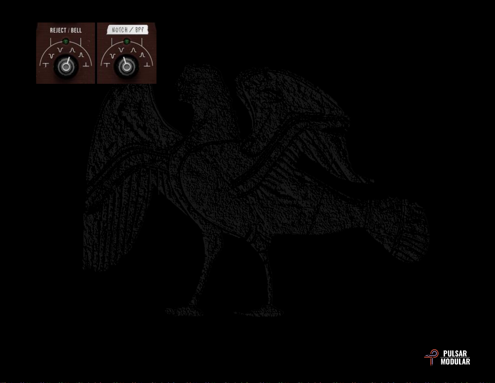
engaged. See the RESONANCE and NOTCH/PEAK band filter
selector documentation for details of these features.
The 12 dB/oct (2-pole), 24 dB/oct (4-pole) filters follow a familiar
sound and design as indicated by the markings under their
respective labels. The 18 dB/oct (3-pole) slope on the other hand
is intended for more creative manipulation and features more
radical Q values. These are simply intentions and not rules
though –use your ears and choose whatever sounds best!
The HPF cutoff frequency knob sets the
point from where the high pass filter
starts working.
When in continuous mode, it features a
frequency range of 20 Hz to 7.5 kHz.
When in stepped mode, available
frequencies are 70, 100, 150, 250, 500,
1000, 2000, 3000, 5000 and 7500 (in
addition to the lower frequency limit as describe above).
Frequencies above the cutoff frequency are unaffected and
frequencies below the cutoff frequency are cut.
If the envelope follower is engaged and the envelope follower
routing knob is pointing to the HPF cutoff frequency knob, the
LEDs will move counterclockwise or clockwise according to the
parameters set in the envelope follower to indicate negative or
positive cutoff frequency movement.
This filter can optionally be turned off using the red light beside
the HPF label.
The HPF RESONANCE knob is used to either add
positive feedback or to remove, flatten and smooth
out the transition curve.
The default position has a Q of 0.707. Increasing
this value adds positive feedback that peaks at the
HPF cutoff frequency, resulting in very rich
harmonic behavior.
As the knob is turned clockwise from the default position,
overtones, coloration and harmonic emphasis of the frequencies
around the cutoff become increasingly audible.
As the knob is turned counterclockwise from the default position,
the Q is decreased, resulting in a lessening of harmonic behavior
and a perceptibly smoother and mellower curve.
Note: When the resonance knob is turned to roughly 4/10 of
the full range, it will begin to self-oscillate. Be very careful with
this feature because it can produce high amplitude high or low
frequencies that are inaudible, but that may push or even
damage equipment.
Important: Siren does not include a limiter or clipper in its
design, so to take advantage of the behavior described above