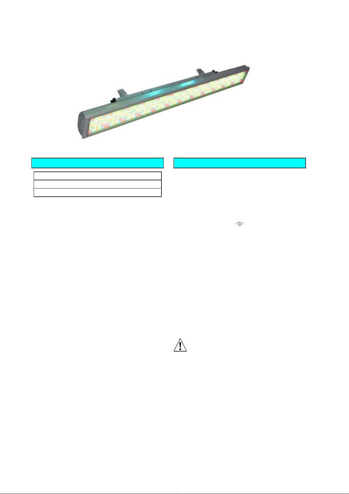
USER INTERFACE MODULE AND FUNCTIONS
LCD DISPLAY A 2 line, 16 character per line, LCD display is
used to set up, and indicate the status of, the ChromaBank IP.
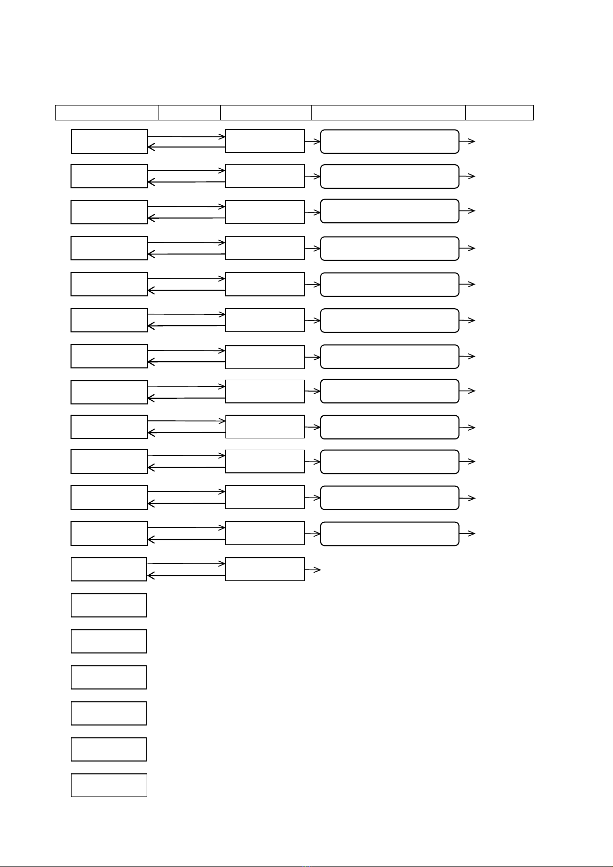
At switch on, the display shows:
Press the (Up) or (Down) keys to cycle through the Menu
Options (see LCD Display Sheet).
Press the X key on the UIM to change the settings.
Note: Program Mode self cancels after ~30 seconds if no keys have
been pressed.
Note: if, at any time, the display shows Receiving: ERROR, then
there is a problem with the DMX signal. It could be wiring,
termination or poorly implemented DMX.
●DMX Address – depending on the operating mode, a block
of 3, 6, 9, 10, 36, 42 or 46 channels is received from the DMX signal
– see Channel Assignments Tables. The DMX Address is the
number of the first channel in the block.
To set the required DMX Address, press the or keys on the
UIM until the display shows DMX Address:
Press the X (change) key on the UIM, then set the start address
using the or keys. These keys repeat if held down.
When the required DMX Address number shows in the display,
press the (Yes) key to save changes or X (Back) key to restore
the previous settings.
Note: the Receiving: text (NO SIGNAL / PMX / DMX / ERROR) in
the display is for information only.
●ChromaZone Mode - the unit can be run in similar modes
to the ChromaZone. The options are 3, 6, 9, 10, 36, 42 and 46
channel modes – see Channel Assignments Tables.
To set the required Mode, press the or keys on the UIM until
the display shows ChromaZone Mode:
Press the X (change) key on the UIM, then select the required mode
using theor keys.
When the required ChromaZone Mode shows in the display, press
the (Yes) key to save changes or X (Back) key to restore the
previous settings.
●Channels per Fixture – the ChromaBank IP 100 is 18
channels per fixture, the ChromaBank IP 200 and 300 are 36
channels per fixture.
To view the number of Channels per Fixture, press the or
keys on the UIM until the display shows Channels per Fixture :
Pressing the X (change) key on the UIM, followed by the or
keys will have no effect.
Press the (Yes) key or X (Back) key to return to the main menu.
●Fixture number: the 36 RGB outputs from the built in
ChromaZone are divided into fixture groups. 36 divided by the
channels per fixture (see above) gives the number of fixtures
available from the data block.
A ChromaBank IP 200 or 300 can only be Fixture 1.
Pressing the X (change) key on the UIM, followed by the or
keys will have no effect.
Press the (Yes) key or X (Back) key to return to the main menu.
A ChromaBank IP 100 may be either Fixture 1 or Fixture 2,
displaying the LED segments as 1-6 of 12 or 7-12 of 12. See the
Channel Assignments Table for channel and fixture number colour
details.
To set the required fixture number, press the or keys on the
UIM until the display shows Fixture number:
Press the X (change) key on the UIM, then select the required
number using the or keys.
When the required Fixture number shows in the display, press the
(Yes) key to save changes or X (Back) key to restore the previous
settings.
●Chase patterns: may be 6 or 12 way. E.g. two
ChromaBank IP 100s, the first set as Fixture 1 of 2 and the second
set as Fixture 2 of 2 will run a 12 way chase.
To set the required chase patterns, press the or keys on the
UIM until the display shows Chase patterns:
Press the X (change) key on the UIM, then select 6 or 12 way using
the or keys.
When the required chase pattern way number shows in the
display, press the (Yes) key to save changes or X (Back) key to
restore the previous settings.
●Channel 10: may be set as a Grand Master for the 36 RGB
channels only, OR as a Global Grand Master for the 36 RGB
channels, the ALL Red ,Green and Blue, and the Chase Levels
To set the required Ch.10 mode of operation, press the or keys
on the UIM until the display shows Ch.10…:
Press the X (change) key on the UIM, then select the required
number using the or keys.
When the required Ch.10 operation shows in the display, press the
(Yes) key to save changes or X (Back) key to restore the previous
settings.
●Input Smoothing - ON or OFF. To disable the input
smoothing, e.g. for fast response to video graphics signals, set to
OFF
To turn the Input Smoothing ON/OFF, press the or keys on
the UIM until the display shows Input Smoothing:
Press the X (change) key on the UIM, then select the required state
using theor keys.
When the required state shows in the display, press the (Yes) key
to save changes or X (Back) key to restore the previous settings.
●Low Voltage Supply - ON or OFF. To connect the LVS to
pin 5 of the MALE XLR, set to ON.
The LVS is used to power some PULSAR controllers, e.g. Outstation
OS1. 24V at up to 250mA d.c. is available.
To turn the Low Voltage Supply ON/OFF, press the or keys
on the UIM until the display shows Low Voltage Supply is:
Press the X (change) key on the UIM, then select the required state
using theor keys.
When the required state shows in the display, press the (Yes) key
to save changes or X (Back) key to restore the previous settings.
●DMX Line Termination –ON or OFF, set the last unit in
the DMX cable run to ON, all others to OFF. Errors can often occur if
the DMX line is not terminated. DMX errors are shown in the display
as:
To turn the DMX Line Termination ON/OFF, press the or keys
on the UIM until the display shows DMX Line Termination:
Press the X (change) key on the UIM, then select the required state
using the or keys.
When the required state shows in the display, press the (Yes) key
to save changes or X (Back) key to restore the previous settings.
●If NoSignal use: In the event the ChromaBank IP is not
receiving a DMX signal (e.g. controller no longer present), the unit
may either use the user-programmable Stand Alone Settings (see
Stand Alone Settings View/Change below) OR continue to use the
Last DMX Packet received.
To select the If NoSignal use: requirement, press the or keys
on the UIM until the display shows If NoSignal use
Press the X (change) key on the UIM, then select the requirement
using the or keys.
When your requirement is showing in the display, press the (Yes)
key to save changes or X (Back) key to restore the previous settings.
●Stand Alone Settings View/Change
There are three possibilities depending on:
a) whether there is an input signal and
b) whether "If NoSignal use:" is set to "Stand Alone Mode" or set to
"Last DMX Packet".
1. No Signal + Use Stand Alone Mode:
The current Stand Alone Settings may be viewed, changed and
saved as the new Stand Alone Settings.
2. No Signal + Use Last DMX Packet:
The channel levels of the Last DMX Packet (if any) may be viewed,
changed and saved as the new Stand Alone Settings.
3. Signal present:
The incoming signal overwrites any changes made but these
incoming channel levels may be set at the controller, viewed and
saved as the new Stand Alone Settings.
DMX Address: n
Receiving: ERROR
DMX Address: n (where n=1 to 512)
Receiving:NO SIGNAL or DMX or PMX or ERROR