Pulse fitness 225F User manual

225F
MAINTENANCE
GROUP CYCLE


Contents
1. Contents of 225F Exercise Cycle Pack and Assembly 4
2. Introduction 8
2.1 Features 8
2.2 Technical Data 9
3. Installation 10
3.1 Location 10
3.2 Installation Procedure 10
3.3 Correct Fitment of the Saddle 11
3.4 Check the Brake Cable 11
3.5 Free Wheel Test (12-Revolutions) 11
4. Operational Information 12
4.1 Operational Information 12
4.2 Correct Height/Positioning of Saddle 12
4.3 Correct Height/Positioning of the Handlebars 12
5. Maintenance 13
5.1 Servicing and Lubrication 13
5.2 Maintenance - Daily 14
5.3 Maintenance - Monthly 16
5.4 Brake Pad Adjustment 17
5.5 Maintenance - Tension Stem Locknut 18
5.6 Maintenance - Replacement of Brake Cable 18
5.7 Maintenance - Drive Belt 19
6. Emergency Stop Brake Lever / Tension Barrel 20
6.1 Emergency Stop Brake Lever 20
6.2 Tension Barrel 20
7. Troubleshooting 21
8. Spare Parts List 22
9. Spare Parts Illustration 24
10. Declaration of Conformity 25
11. Engineers Service History 26
12. User’s Notes 27
3
Saddle
Handlebars
Emergency Stop
Brake Lever
Handlebar
Knob
Adjuster
Main Frame
Front Foot
Pedals
Rear Foot
Bottle Cage

1 225F Cycle Flat Pack
The Pulse 225F Exercise Cycle
will have to be assembled from
the flat pack. The contents of
the pack are as follows:
This Manual
Main Body
Saddle
Pedals and Foot Straps
Rear Foot Strut
Front Foot Strut
Bottle
Bottle Cage
Handlebars
Handlebar Adjuster Knob
Adjuster Knob Washer
Feet Strut Bolts & Washers
Water Bottle Cage Screws
Emergency Stop Brake Lever
Lateral Seat Adjuster
If any parts are missing then
please contact Service Dept.
+44(0)1260 294600.
A
B
C
D
E
F
G
H
I
J
K
L
M
N
O
4
M
L
K
x 2
x 4
B
C
G
A
E
I
D
F
H
J
N
4
O
x 2

1 Assembly of the 225F
Place the main body onto the
feet struts, making sure the
front and rear feet struts are
the correct way around (this is
a two person procedure).
Then secure tightly with feet
strut bolts and washers.
Attach the saddle and secure
tightly, (see Section 3.3 on
Page 11).
Check the crank bolts are
securely fastened.
NOTE: Use a torque setting of
70 Nm.
Attach the pedals onto the
crank arms (the pedals are
handed and therefore should
be attached as indicated by the
letter L or R on the underside
of the pedal).
NOTE: Ensure the pedals are
securely fastened before using
the cycle.
Mount the bottle cage onto the
main frame.
NOTE: Do not over tighten.
Tools Required:
1 x 15/13mm Combination
Spanner.
1 x 6mm Allen Key.
1.
2.
3.
4.
5.
1
2
4
3
1
3
5

56
Attach the handlebars to the
main frame using the
handlebar adjuster knob and
adjuster knob washer, (ensure
the knob is tight and secure).
Attach the emergency stop
brake lever/tension barrel
using an allen key and secure
tightly.
NOTE: Ensure that all bolts are
securely tightened.
Tools Required:
1 x 6mm Allen Key.
5.
6.
6

GENERAL SAFETY PRECAUTIONS
The successful and safe operation of the Group Exercise Cycle is dependent upon its proper handling, installation operation and maintenance.
The following safety precautions are for your safety and guidance. Please read them carefully before proceeding to install and/or operate the
Group Exercise Cycle. Specific safety notices are included in the text where appropriate.
Read through this operating handbook to familiarise yourself with the equipment.
Trained personnel should supervise all training and rehabilitation sessions.
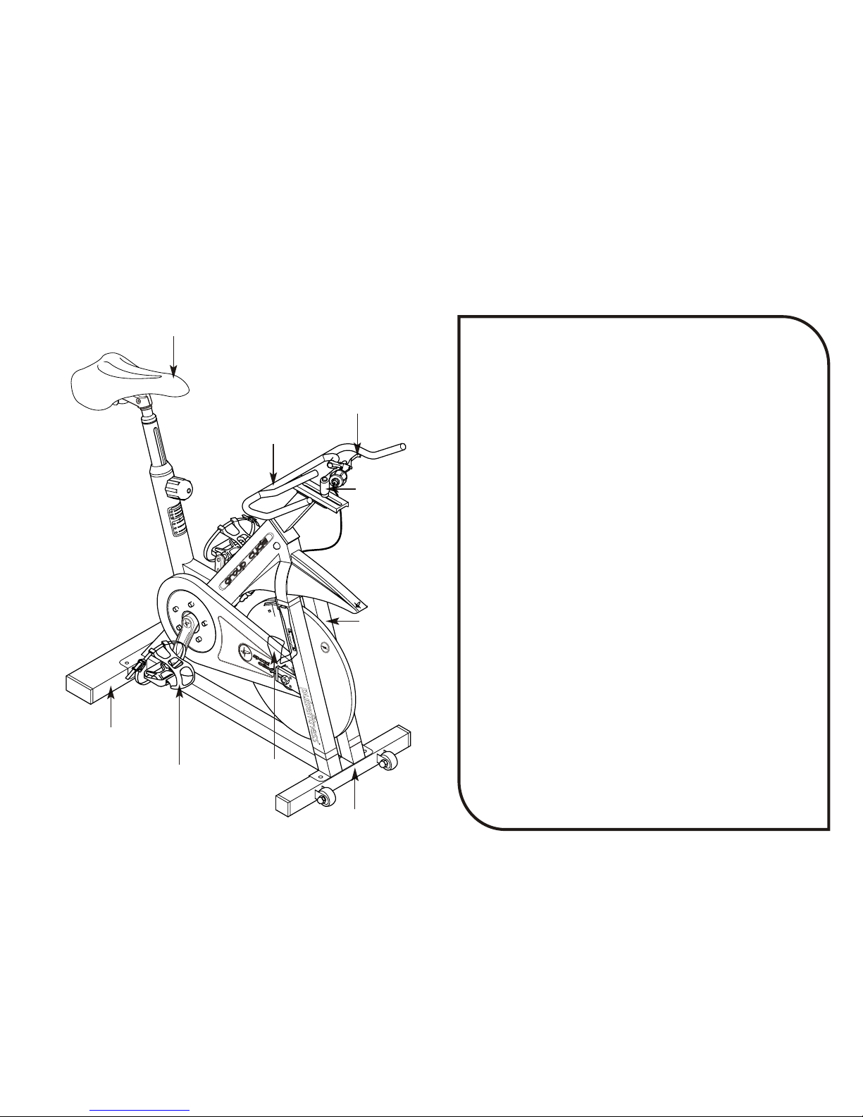
Check the crank arms daily for any signs of stress fatigue and check the pedals for spindle wear as shown in Section 5.
The correct use of Pulse Fitness machines is of paramount importance. The machines should be adjusted to suit each individual and care
should be taken when starting and completing an exercise session.
Ensure that all users of the equipment are familiar with these safety precautions and operating procedures.
Persons who are generally unfit (i.e. have not taken regular exercise for some time) should seek expert advice before using this equipment.
Similarly, persons with known medical conditions (e.g. angina, asthma, high blood pressure, etc.) should seek medical advice.
Always warm up by exercising gently before progressing to a full programme of strenuous exercise. Similarly, reduce your level of activity
gradually towards the end of your exercise programme.
NOT suitable for medical/therapeutic purposes.
If you feel light-headed, dizzy or suffering from any kind of pain whilst exercising, STOP IMMEDIATELY.
Seek medical attention immediately if injury is incurred.
Do not drink from bottles or cups without a lid. Do not place cups/bottles anywhere on the machine except from in the supplied bottle holder.
Keep limbs clear of moving parts. Do not wear loose clothing or jewellery that may become entangled with moving parts.
Keep an area of 1 metre clear around the Group Exercise Cycle when operational; a crowded room is a hazard.
WARNING, excessive or incorrect training can be detrimental to your health.
Do not allow children to train unsupervised on the Group Exercise Cycle.
Exchange faulty parts IMMEDIATELY with ONLY genuine Pulse Fitness parts. Do not use equipment until repaired.
The flywheel momentum of the bike will keep the pedals turning even after the user stops pedalling or in the event the user’s feet slip off the
pedals. Do not dismount the bike or attempt to remove your feet from the pedals until both the pedals and the flywheel have stopped completely.
Failure to comply may lead to loss of control and serious personal injury.
7

2 Introduction
The Pulse Group Exercise Cycle is a sophisticated heavy duty
exercise bike, designed specifically for use in a Health & Fitness
type environment. It is suitable for both aerobic and anaerobic
exercise and general athletic fitness training or weight-loss
programmes.
The main reason for this publication is to enable the owner to
maintain, service and purchase replacement parts. The company
retains the right to make alterations to the design and specification
of the machine at any time and accepts no responsibility for any
discrepancies between machine specification and descriptions
contained within this publication. It is the owners responsibility to
comply with the following manufacturers instructions on machine
maintenance and servicing. These instructions do not affect your
statutory rights.
Important notes:
Confirm that the machine has not been damaged in transit.
Maintenance, servicing and replacement parts must be carried out
by a competent person.
All safety guards must be properly secured before using this
machine.
Use only genuine Pulse Fitness spare parts, to order quote the part
number and quantity required, order from,
Pulse Fitness, Tel: +44 (0)1260 294600 Fax: + 44 (0)1260 299282
2.1 Features
?Ergonomically-designed workout position.
?Emergency Stop Brake Lever.
?Tension Barrel.
8
Figure AFigureA Pulse 225F Group Exercise Cycle

2.2 Technical Data
Dimensions: 225F Group Exercise Cycle
Length: 1.05 m
Width: 0.505 m
Height: 1.03 m
Weight: 70 kg
Note: The Pulse 225F Group Exercise Cycle uses a patented speed independent braking system.
9

WARNING
When installing or adjusting any piece of Pulse Fitness
equipment, DO NOT leave any adjustment devices projecting
which could cause injury to any third party.
3 Installation
3.1 Location
Select a suitable location for the Exercise Cycle before moving it.
The site you choose should meet the following requirements:
A flat, level and clean surface.
Well away from sources of water (or other liquids) or in an area
that is subject to condensation.
NOTE: The 225F Group Exercise Cycle is not suitable for outdoor
use.
3.2 Installation Procedure
Once the Exercise Cycle has been sited you must ensure that it is
stable. If necessary, adjust the height of the front adjustable
suspension feet to compensate for any unevenness in the floor.
Turn the front feet to the left or right to increase or decrease the
height as appropriate, (see Figure B). When satisfied, securely
fasten the locknut up against the Feet Strut. The rear adjustable
suspension feet should be inserted fully into the Feet Strut and
not used for unevenness correction.
To protect the paintwork from sweat, wipe down the metal frame
with a wax/silicone-based polish.
CAUTION
This equipment is heavy! We do not recommend attempting
to lift it without assistance; at least 2 people should lift the
Exercise Cycle when necessary.
To move the Exercise Cycle, hold the handlebars and push
down to get the bike balanced on the front feet caster rollers,
then push or pull to its desired position.
10
Figure B Feet Adjustment
Adjustable
Suspension feet
Locknut

3.3 Correct Fitment of the Saddle
The clamps are positioned along the saddle rails, (see Figure C).
When in position ensure the clamp is fully seated onto the post
and the saddle is level, then tighten the clamp nuts equally on
both sides to secure the saddle to the seat post.
NOTE: Double-check the clamp nuts are tightly fastened and the
saddle is securely attached onto the seat post before
commencing exercise.
3.4 Check the Brake Cable - is adjusted by turning the cable
barrel clockwise (opposite direction to the arrows) until it has no
more adjustment, then see if there is any play or movement when
the cable enters the tension barrel, (see Figure N on Page 16).
If adjustment is required, (see Section 5.4 on Page 17).
3.5 Free Wheel Test (12-Revolutions) - The purpose of this test
is to ensure that the brakes are correctly adjusted.
Make sure all tension is released from the brake pads and that the
brake is fully off. Place your foot on the pedal and spin them to a
speed or approximately 60rpm, (see Figure D), quickly take your
foot off and count the amount of revolutions it takes until the
pedals stop moving. If the amount of revolutions are above 12 the
Exercise Cycle is set up correctly and needs no alteration.
However, if the revolutions are set below 12. See Section 5.4 for
brake pad adjustment.
NOTE: By performing the free wheel test, this will ensure there is
no resistance on the Exercise Cycle when on the minimum
setting. Failure to calibrate the Exercise Cycle in this way, may
cause discomfort to the user.
WARNING
Take extreme care when removing your foot off the pedal, to
avoid crank arm hitting into your leg or foot and causing
serious injury.
11
Figure D Free Wheel Test (12-Revolutions)
60 rpm
Figure C Correct Fitment of the Saddle
CLAMP SADDLE
SADDLE RAIL
POST
INDEX CLAMPING HANDLE

4.1 Operational Information
Before using the Pulse 225F Exercise Cycle, familiarise yourself
with the bike to ensure that you understand the basic principles
of the cycle.
Inspect the cycle for any damaged or worn parts and for general
smooth / safe operation. Do not use the cycle if any part appears
worn, damaged or faulty.
4.2 Correct Height / Positioning of the Saddle
Adjust the saddle so that when the user stands directly behind
the cycle the saddle is just below the users navel. Hold the seat
in one hand and unscrew the seat post clamping knob by turning
it anti-clockwise, (see Figure E). This position should suit most
users, however, adjustment should be made if the user feels
uncomfortable. Adjustment can also be made by releasing the
Saddle Adjustment Knob and sliding the saddle forwards or
backwards to customise riding position.
NOTE: Only tighten the Seat Post Clamping Knob to finger tight,
this is all that is required to hold the seat post firm due to its
design. If the Knob is over tightened threads can be stripped.
4.3 Correct Height / Positioning of the Handlebars
Adjust the handlebars so that they are level with the height of the
saddle, (Figure F).
The handlebars should always be left in the “Neutral Position”,
(see Figure F), where by laterally the bottom handgrip should be
in line with the top edge of the handlebar post. This position
should suit most users, however, adjustment can be made by
releasing the Handlebar Adjustment Knob and sliding the
handlebars forwards or backwards to suit a longer shorted reach
respectively.
Place balls of feet onto the pedals and adjust toeclips so that the
feet are held onto the pedals.
Ensure that the riding position is comfortable before
commencing strenuous exercise.
Alter the brake resistance by turning the tension barrel in the
direction as indicated by the arrows.
4 Operational Information
12
ADJUST HEIGHT OF SADDLE
TO JUST BELOW NAVEL
Figure F Correct Positioning of the Handlebars
LEVELLINE BETWEEN
HANDLE BARSAND SADDLE
HANDLE BARS IN
THE NEUTRALPOSITION
Figure E Correct Height / Positioning of the Saddle
SADDLE
SADDLE

5.1 Servicing and Lubrication
WARNING!
Make sure you know the different parts of the Exercise Cycle
before you attempt to carry out any maintenance as shown in this
section, (see Figures G and H).
Use extreme care when servicing the bike with the guards
removed. If fingers or other parts of the body come into contact
with moving parts inside of the cycle, amputation or other serious
injury may occur. Prior to commencing any maintenance on the
belt drive, familiarise yourself with all moving parts. Never leave
the Exercise Cycle unattended.
Servicing must be carried out by a competent person.
It is recommended that the machine is checked and serviced at
regular intervals depending on the usage.
Be sure to replace all guards after servicing.
Prior to use, apply a coat of silicone sealant to all painted areas
of the Pulse 225F Group Exercise Cycle, excluding the flywheel.
Make sure all tension is released from the brake pads after each
use, for the comfort of the next user.
5 Maintenance
13
TENSION BARRELHANDLE BARS EMERGENCY STOP
BRAKE LEVER
HANDLEBAR
ADJUSTMENT
KNOB
Figure G Handlebar Arrangement
Figure H Flywheel and Brake Assembly
ADJUSTMENT
BARREL
BRAKE PADS
FLYWHEEL
INNER BRAKE
CABLE
INNER BRAKE CABLE
SECURING NUT
BRAKEADJUSTMENT
LOCK NUT

5.2 Maintenance - Daily
General - Inspect for any loose parts, nuts, bolts, etc.
Check Footstraps - for any signs of wear or damage, replace
footstraps if required, (see Figure I).
Check Crank Arms - for any signs of damage or fatigue on both
crank arms, especially where the pedals locate or around the
attachment points to the bike, see (Figure J).
NOTE: If any sign of damage or fatigue is evident, the crank arms
must be replaced immediately.
Clean the Frame - Using a clean, dry cloth wipe down the cycle
to remove any perspiration after each workout. For hygiene
purposes wipe down the rubber coated handlebars and exercise
saddle with a mild soapy solution and, for extra protection, clean
the frame at least once a day with a silicone based polish.
NOTE: For best results use a good quality automotive polish.
Re-seal and lubricate if and where necessary.
WARNING
Failure to follow the Daily and Monthly inspections detailed in
this manual, could result in serious injury.
14
FOOT STRAPS
Figure I Footstraps
Figure J Crank Arms

Check Pedals - for any damage and especially wear in the
spindle. To check the spindle hold the pedal firmly and try to
move the pedal up and down and back and forwards for any
signs of movement or clicking, (see Figure K). If there is any
movement replace immediately.
Check Seat Clamps - Ensure the seat clamp is securely
fastened onto the post in order to prevent movement that could
result in injury.
General Function Test - check for stability, braking and general
smooth operation, this is best achieved by getting on the Group
Exercise Cycle and pedalling for a minute or two, making sure
that everything feels correct and secure.
15
Figure K Pedals

5.3 Maintenance - Monthly
Clean the Frame and Flywheel - Re-apply a coat of silicone
polish to all the painted frame areas of the Exercise Cycle
including the flywheel, except where the brake pads come into
contact with it, (see Figure L).
NOTE: For best results use a good quality automotive polish.
Check the Brake Pads - Visually check and renew if necessary,
(see Figure M). When fitting new brake pads please ensure you
perform the Free Wheel Test as detailed in Section 3.5 on Page
11.
NOTE: The life expectancy of the brake pads is between 1-3
years, depending on the number of classes.
Check the Brake Cable: is adjusted correctly by turning the
tension barrel clockwise (opposite direction to the arrows) until it
has no more adjustment, then see if there is any play or
movement where the cable enters the tension barrel, (see Figure
N). If adjustment is required, (see Section 5.4 on Page 17).
16
FLYWHEELAREA
TO CLEAN
Figure L Cleaning the Frame & Flywheel
Figure M Checking the Brake Pads Figure N Checking the Brake Cable

5.4 Brake Pad Adjustment
For minor adjustment of the brake pads, use the Adjustment
Barrel (B). Firstly slacken the Brake Adjustment Lock Nut (A), and
rotate the Adjustment Barrel (B) in the direction of the arrow (anti-
clockwise). If satisfied with the adjustment re-tighten the Brake
Adjustment Lock Nut (A).
However if there is still play in the brake cable, (see Figure N on
page 16), it will be necessary to adjust the cable.
Firstly slacken the Brake Adjustment Lock Nut (A), then adjust the
Adjustment Barrel (B), by rotating clockwise fully into the calliper.
Slacken off the Inner Brake Cable Securing Nut (C).
Squeeze the brake pads tightly against the flywheel, and pull the
inner brake cable with thumb and forefinger to remove any slack,
(be careful not to pull the Brake Cable End Cap off (D)), (see
Figure O), re-tighten the Inner Brake Cable Securing Nut (C).
Then check the Free Wheel Test (12-Revolutions) (see Section 3.5
on Page 11) and if required, fine adjust the brake pads as
described from the beginning of Section 5.4.
17
ANTI CLOCKWISE
MOVEMENT
INNER BRAKE CABLE
SECURING NUT - C
BRAKE CABLE
END CAP - D
BRAKEADJUSTMENT
LOCK NUT - A
ADJUSTMENT
BARREL- B
Figure O Brake Pads Adjustment

5.5 Maintenance - Tension Stem Locknut
The Tension Stem Locknut should always be tight up against the
collar and brake lever. If it is found loose then tighten up
immediately to allow the Exercise Cycle to function properly (see
Figure P).
5.6 Maintenance - Replacement of Brake Cable
To replace the brake cable, first slacken the inner brake cable
securing nut. Pull the brake lever on and carefully push the brake
cable through the brake lever to create some slack, then release
the brake cable retaining lug by pushing the lug down through the
hole in the housing. Hold the lug and pull the remaining cable out
through the handle and clear of the Exercise Cycle. Thread the
new cable back through the brake handle and tension barrel,
insert the retaining lug up into its housing and push the brake
lever off whilst pulling on the cable. Thread the cable through the
brake cable sleeve and route down to the brake pads. Route the
cable firstly through the adjustment barrel then the brake calliper,
insert the cable behind the cable securing nut and tighten. The
brake pads will need re-setting and the Free Wheel Test will have
to be checked, (see Section 5.4 on Page 17).
NOTE: The brake cable and brake cable sleeve is replaced as a
complete assembly, therefore if one is renewed so is the other.
Tools Required -
1 x 21mm A.F.Spanner
18
TENSION STEM LOCKNUT
COLLAR
BRAKE LEVER
HANDLE BARS
Figure P Tension Stem Locknut
Figure Q Replacement of Brake Cable
INNER BRAKE
CABLE
SECURING NUT BRAKE CABLE
SLEEVE
BRAKE HANDLE
BRAKE CABLE
RETAINING LUG
BRAKE CABLE
END CAP

5.7 Maintenance - Drive Belt
Check for belt slip: this is done by firmly applying the brake lever,
stand on the pedals and apply a heavy load. If the belt slips
adjustment is required, (you may have to remove the belt guard to
adjust the belt tension).
Adjustment is achieved by slackening the flywheel securing nuts
on both sides of the flywheel. Using the drive belt adjusting the
screws adjust by half a turn equally on both sides to tension the
belt, re-tighten the flywheel securing nuts and check for belt slip.
Repeat the process until belt slip is non-existent, (see Figure R).
NOTE: Be careful of the direct drive flywheel when the guard is
removed.
Check the belt guard, clean and re-seal with silicone.
Touch up any chipped paint, as any exposed metal is susceptible
to rust.
Check the lock nuts, bolts and grub screws for the seat and
handlebar position, tighten if necessary.
Check that the crank bolts are tight.
NOTE: If you allow clients to use their own clipless pedals, you
will be held responsible for them replacing the pedals correctly. If
the threads become stripped the warranty will not cover this.
WARNING
The safety level of this Exercise Cycle can only be maintained
if the bike is regularly examined for damage and wear, DO
NOT use the machine if any part appears worn, damaged or
faulty.
19
DRIVE BELT
FLYWHEEL
SECURING NUT
NOTE: CYCLE SHOWN WITH BELT COVER REMOVED
DRIVE BELT
ADJUSTMENT SCREW
Figure R Drive Belt Adjustment & Tension

6.1 Emergency Stop Brake Lever
Whilst operating the 225F Group Exercise Cycle the brake can be
used at any time to produce an emergency stop. Simply pull
back the brake lever, (see Figure S) to apply the brake, once
applied the lever must be returned back to its original position to
free the flywheel.
NOTE: The emergency brake should only be used for
emergency braking and not as a constant braking system.
6.2 Tension Barrel
Whilst operating the 225F Group Exercise Cycle the amount of
effort you need to turn the pedals can be increased/decreased
manually. To increase the effort turn the tension barrel, (see
Figure T) in the direction of the arrows marked on the barrel. To
decrease the effort turn the barrel in the opposite direction of the
arrows.
6 Emergency Stop Brake Lever / Tension Barrel
20
BRAKE LEVER
HANDLE BARS
TENSION BARREL
Figure T Tension Barrel
Figure S Emergency Stop Brake Lever
Table of contents
Other Pulse fitness Exercise Bike manuals