4TOLB-3L1
1306, Issue 2, May 1992
6
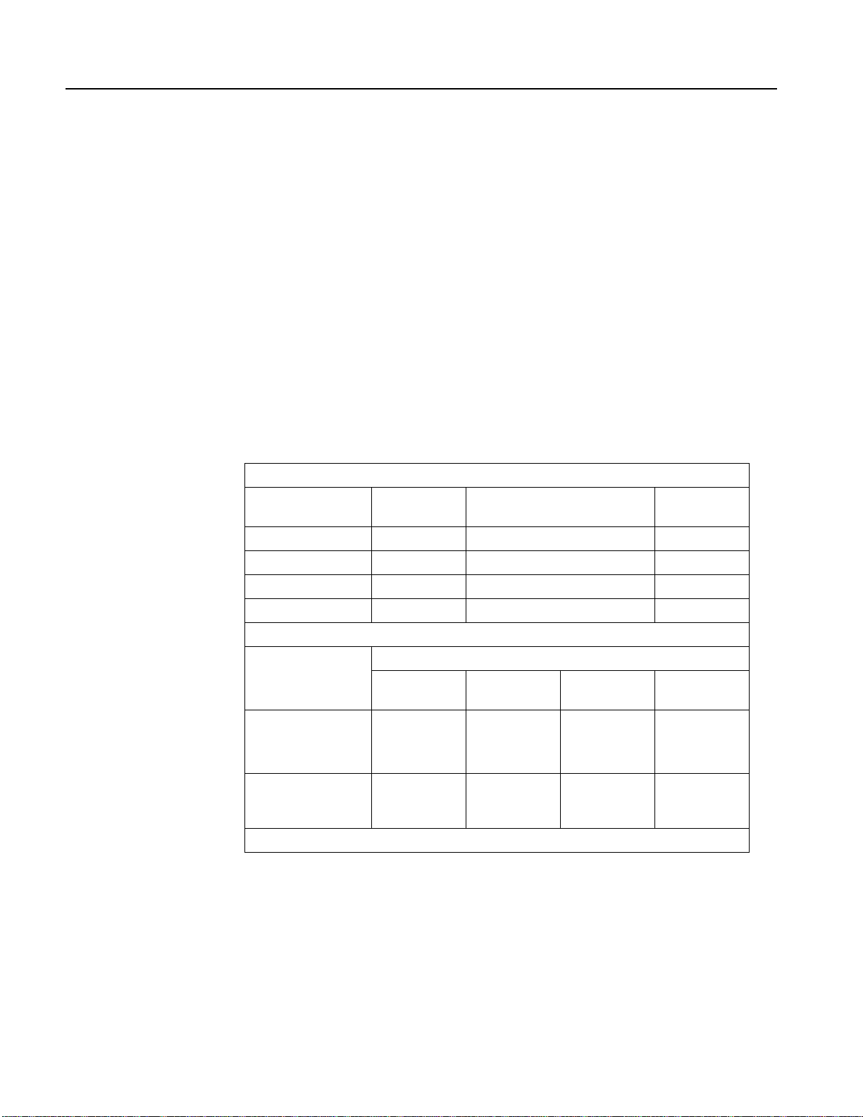
Attenuation
Up to 32.5 dB of attenuation in 0.1-dB steps for the TRMT path and up to 24 dB of
attenuation in 0.1-dB steps for the RCV path can be selected. TRMT attenuation is
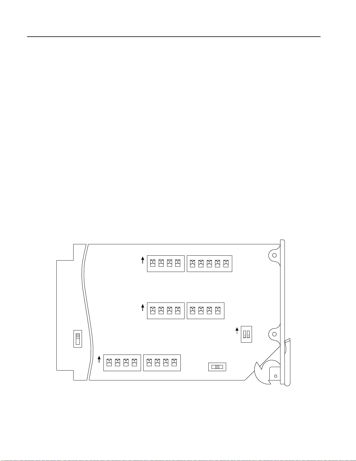
selected at switch blocks S1 and S2; RCV attenuation is selected at switch blocks S3
and S4.
Sealing Current
Switch S5 allows selection of three sealing current modes for the channel unit:
1) In position S5-SRC, the unit provides a momentary current surge (ZAP current) and
then maintains a constant lower-level current through the T/R and T1/R1 cable pairs;
the ZAP current flows automatically when the unit is inserted into the channel bank.
The ZAP current and constant sealing current are used to assure good contact at all
cable splices by removing any high-resistance film caused by oxidation.
2) In position S5-SINK, the unit provides a circuit closure between the T/R and T1/R1
cable pairs; this selection allows current provided by equipment on the metallic side to
flow through the cable pairs.
3) In position S5-OFF, no sealing current will flow through the T/R and T1/R1 cable
pairs.
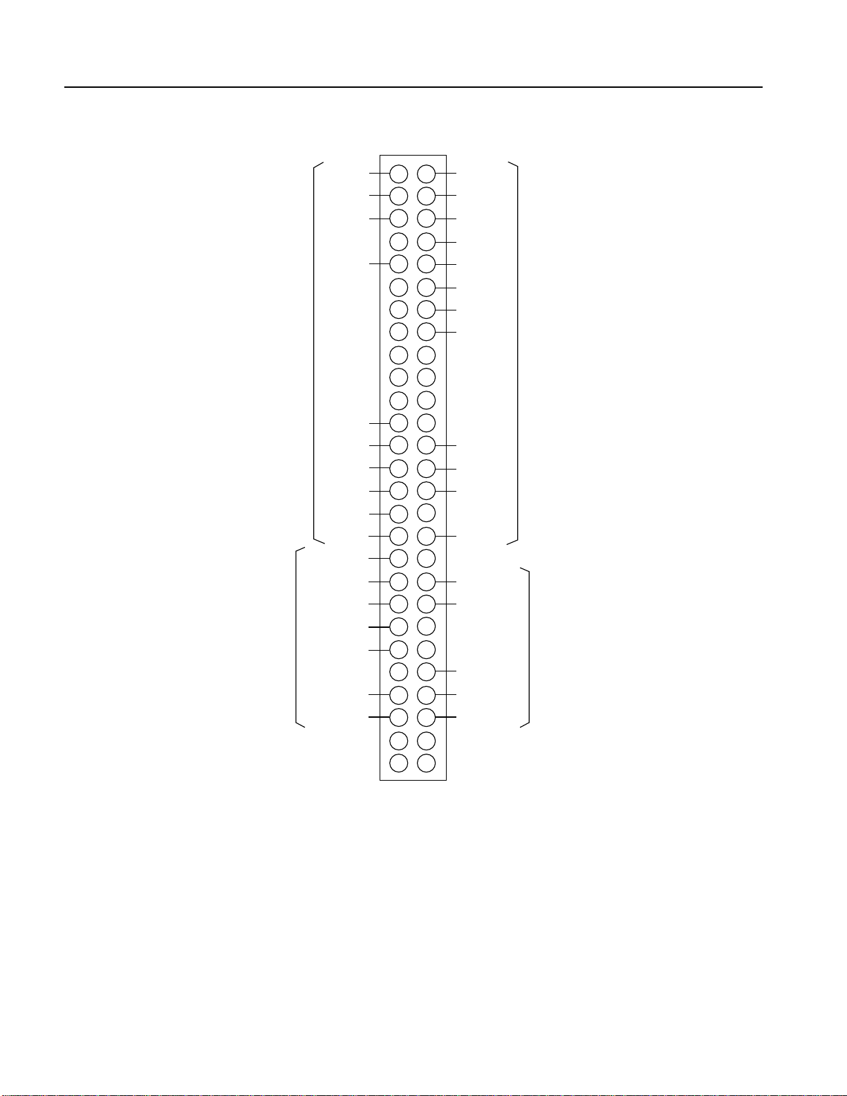
Mounting
Switch S6, which routes the TEK5,TEK6, and LOCAL LB leads to their proper card-edge
connector pins, is selected based upon the type of channel bank into which the unit will be
placed. Select the D4/COT option if using a D4 bank or a SLC 96 central office terminal.
Select RT if the bank is a SLC 96 remote terminal. Note that SLC 96 banks must be
configured to Mode 3 (special services).
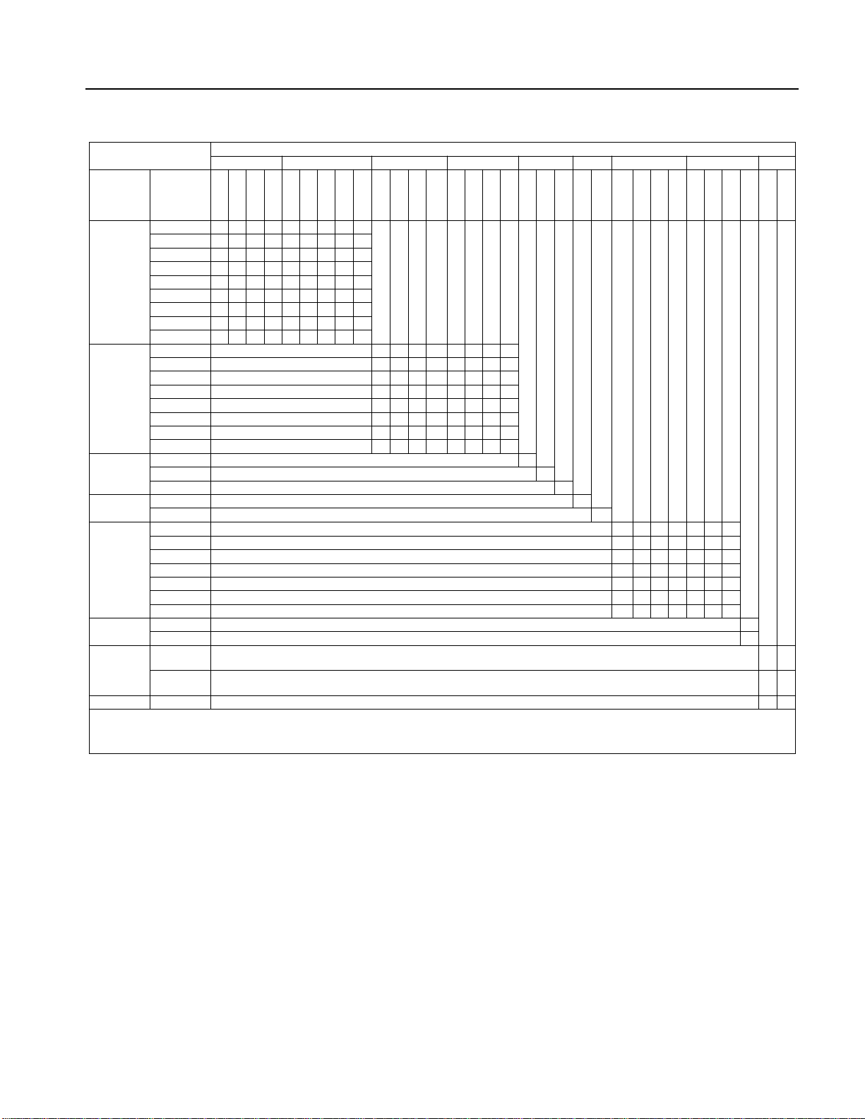
Loopback Gain/Loss
This option allows loopback gain or loss selection from 0 to 31.75 dB. Gain or loss is
selected to maintain the transmission level point (TLP) levels during loopback. The
amount of gain or loss as well as the GAIN/LOSS selection is set at switch blocks S7 and
S8. Switch settings are selected as shown below.
1) Compare the TRMT input and the RCV output levels. If the TRMT level is greater
than the RCV level, select the gain (G) option; otherwise, select loss (L).
2) Subtract the TRMT level from the RCV level and take the absolute value. Round this
value to the nearest 0.25 dB. This number is the value of gain/loss to be selected.
For example, if the RCV TLP has been set to +3.5 dBm and the TRMT TLP to –10 dBm,
then the loopback gain/loss is set to the L position, and +3.5 – (–10) = 13.5 dB of loss is
selected.