Amplifier care b llet points.
Amplifier care b llet points. Amplifier care b llet points.
Amplifier care b llet points.
DO
DO DO
DO …
……
…
1. Read the manual; understand the operation, limitations and safety instructions before using
the product
2. Use good quality cables of the correct type, in the correct sockets. Speaker cables should
be manufactured from 1.5mm
2
or larger cable. Keep speaker lengths as short as possible to
minimise signal loss.
3. Listen to your sound; if it’s distorted, reduce gain, olume or both
4. Use adequate amplification and speakers for your needs
5. Checks the mains supply in the enue; use a mains checker.
6. Ensure your amp, speakers and all cables are free from damage
7. Protect your amp from moisture, smoke/fog machines and glitter cannons
8. Make and check all connections before you switch on
9. Set amp olume to ‘0’ at switch on. Slowly turn up, checking all speakers are working. If
there are problems turn the amp off and resol e them
FOLLOW THE SIGNAL PATH!
FOLLOW THE SIGNAL PATH! FOLLOW THE SIGNAL PATH!
FOLLOW THE SIGNAL PATH!
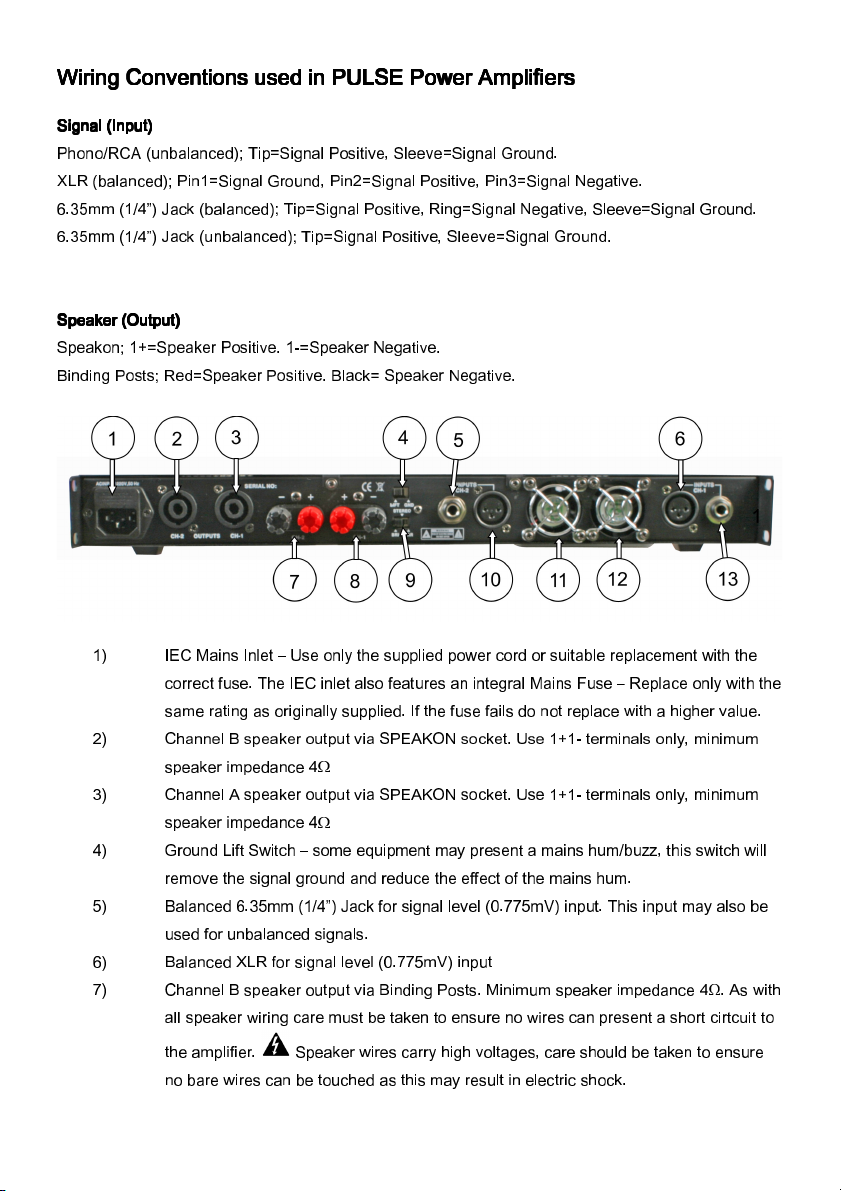
• Source output to mixer/preamp input (shielded signal cable),
• Mixer/preamp output to power amp input (shielded signal cable),
• Power amp output to speaker input (unshielded speaker cable).
DO NOT
DO NOT DO NOT
DO NOT …
……
…
1. Pre ent airflow to your amp; entilation is required front and rear
2. ‘Daisy chain’ speakers. Run a maximum of 1x4Ω speaker or 2x8Ω speaker per amplifier
channel.
3. Run amplifiers with the clip or limit lights on constantly
4. Send a clipped or o erdri en signal from your mixer or source to the amp
5. Store your amp or speakers in a damp en ironment
6. O erload mains sockets; Ne er run more than 3000W of amplifiers, lights or other
electronic equipment from one mains outlet socket.
7. Connect 2 amp channels, or 2 different amps to one speaker
8. Short circuit or cross-connect an amps inputs or outputs
9.
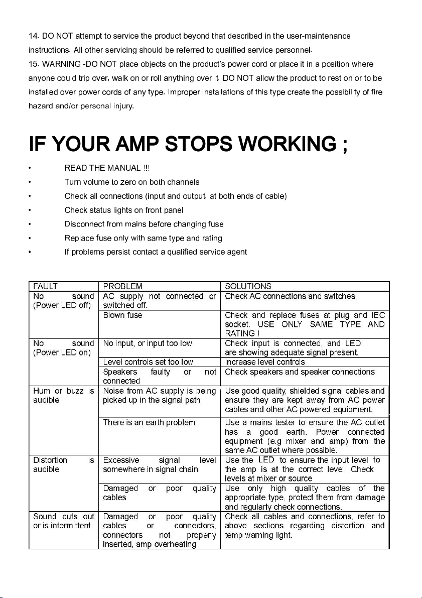
The front panel ha both SIGNAL and CLIP LED indicator
The front panel ha both SIGNAL and CLIP LED indicator The front panel ha both SIGNAL and CLIP LED indicator
The front panel ha both SIGNAL and CLIP LED indicator –
––
–
if the CLIP LED’ illu
if the CLIP LED’ illuif the CLIP LED’ illu
if the CLIP LED’ illuminate
minate minate
minate
reduce the input ignal to the amplifier immediately. A clipped ignal within the audio ignal
reduce the input ignal to the amplifier immediately. A clipped ignal within the audio ignal reduce the input ignal to the amplifier immediately. A clipped ignal within the audio ignal
reduce the input ignal to the amplifier immediately. A clipped ignal within the audio ignal
chain can damage both peaker and amplifier .
chain can damage both peaker and amplifier .chain can damage both peaker and amplifier .
chain can damage both peaker and amplifier .