Pumps Australia COMPACT 120/10 User manual

COMPACT 10/120
USER MANUAL
pumpsaustralia.com.au
1800 790 915

Thank you for purchasing a quality Pumps Australia Unit. We reserve the right to make changes at any time without
incurring any obligation.
Owner/User Responsibility: The owner and/or user must have an understanding of the manufacturer’s operating
instructions and warnings before using this Stand Alone Boiler. Warning information should be emphasized and
understood. If the operator is not uent in English, the manufacturer’s instructions and warnings shall be read to and
discussed with the operator in the operator’s native language by the purchaser/owner, making sure that the operator
comprehends its contents.
Owner and/or user must study and maintain for future reference the manufacturers’ instructions.
The operator must know how to stop the machine quickly and understand the operation of all controls. Never permit
anyone to operate the engine without proper instructions.
This manual should be considered a permanent part of the machine and should remain with it if machine is resold.
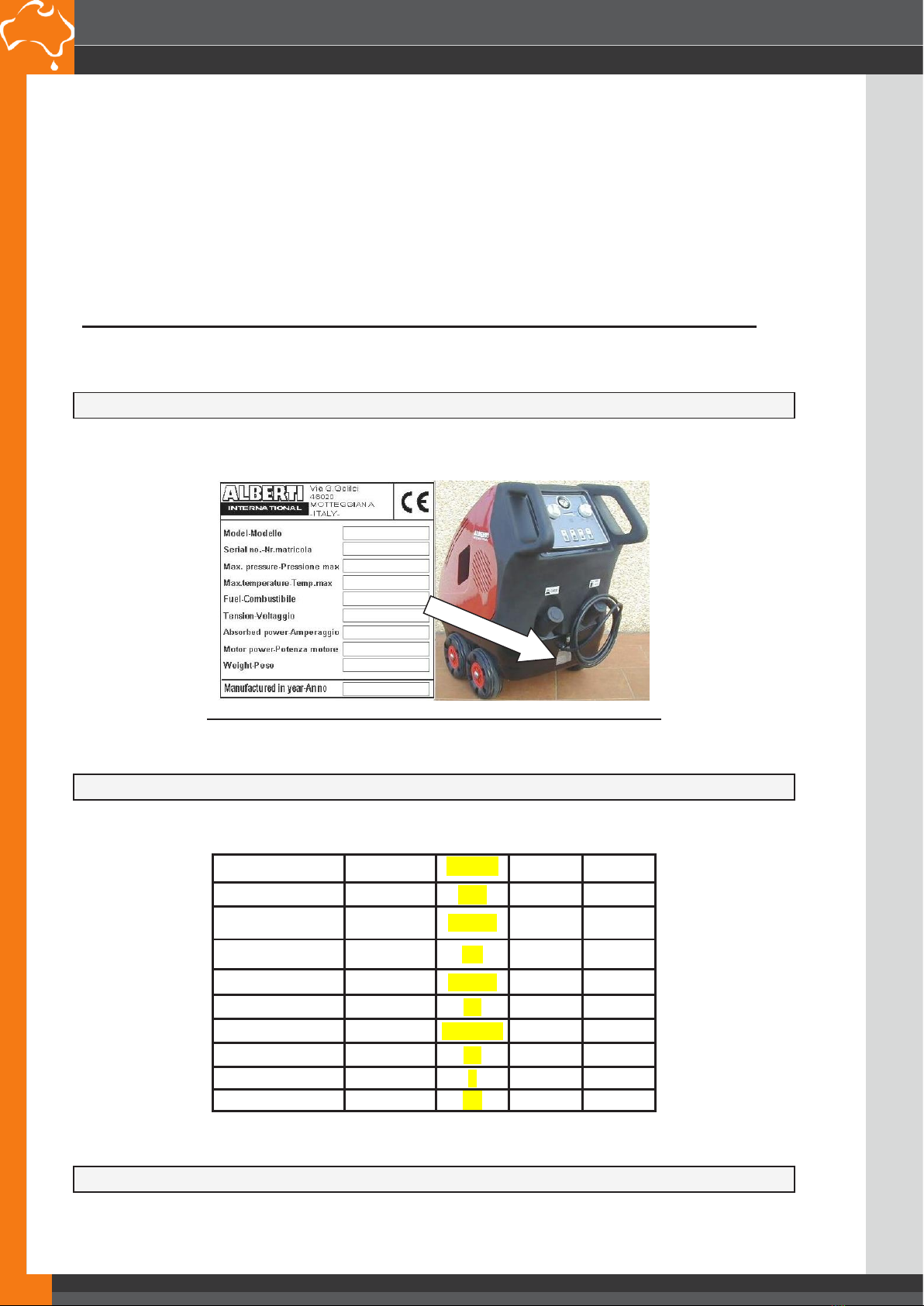
When ordering parts, please specify model and serial number. Use only identical replacement parts. This machine is
to be used only by trained operators.
IMPORTANT SAFETY INFORMATION
2. Know how to stop the machine and bleed pressure quickly. Be thoroughly familiar with the controls.
3. Stay alert — watch what you are doing.
4. All installations must comply with local codes. Contact your electrician, plumber, utility company or the selling
distributor for specic details. If your machine is rated 250 volts or less, single phase will be provided with a ground
fault circuit interrupter (GFCI). If rated more than 250 volts, or more than single phase this product should only be
connected to a power supply receptacle protected by a GFCI
WARNING: To reduce the risk of injury, read operating instructions carefully before using.
1. Read the owner’s manual thoroughly. Failure to follow instructions could cause
malfunction of the machine and result in death, serious bodily injury and/or property
damage.
WARNING: Keep wand, hose, and water spray away from electric wiring or fatal electric
shock may result.
5. To protect the operator from electrical shock, the machine must be electrically grounded. It is
the responsibility of the owner to connect this machine to a UL grounded receptacle of proper
voltage and amperage ratings. Do not spray water on or near electrical components. Do not touch
machine with wet hands or while standing in water. Always disconnect power before servicing.
WARNING: Flammable liquids can create fumes which can ignite, causing property damage
or severe injury.
WARNING: Risk of explosion — Operate only where open ame or torch is permitted.
6. In oil burning models, use only kerosene, No. 1 home heating fuel, or diesel. If diesel is used,
add a soot remover to every tankful.
WARNING: Risk of re — do not add fuel when the product is operating or still hot.
WARNING: Do not use gasoline crankcase draining or oil containing gasoline, solvents or
alcohol. Doing so will result in re and/or explosion.
7. Oil burning appliances shall be installed only in locations where combustible dusts and amma-
ble gases or vapours are not present. Do not store or use gasoline near this machine.
8. Do not allow acids, caustic or abrasive uids to pass through the pump.
9. Never run pump dry or leave spray gun closed longer than 1-2 minutes.
10. Keep operating area clear of all persons.
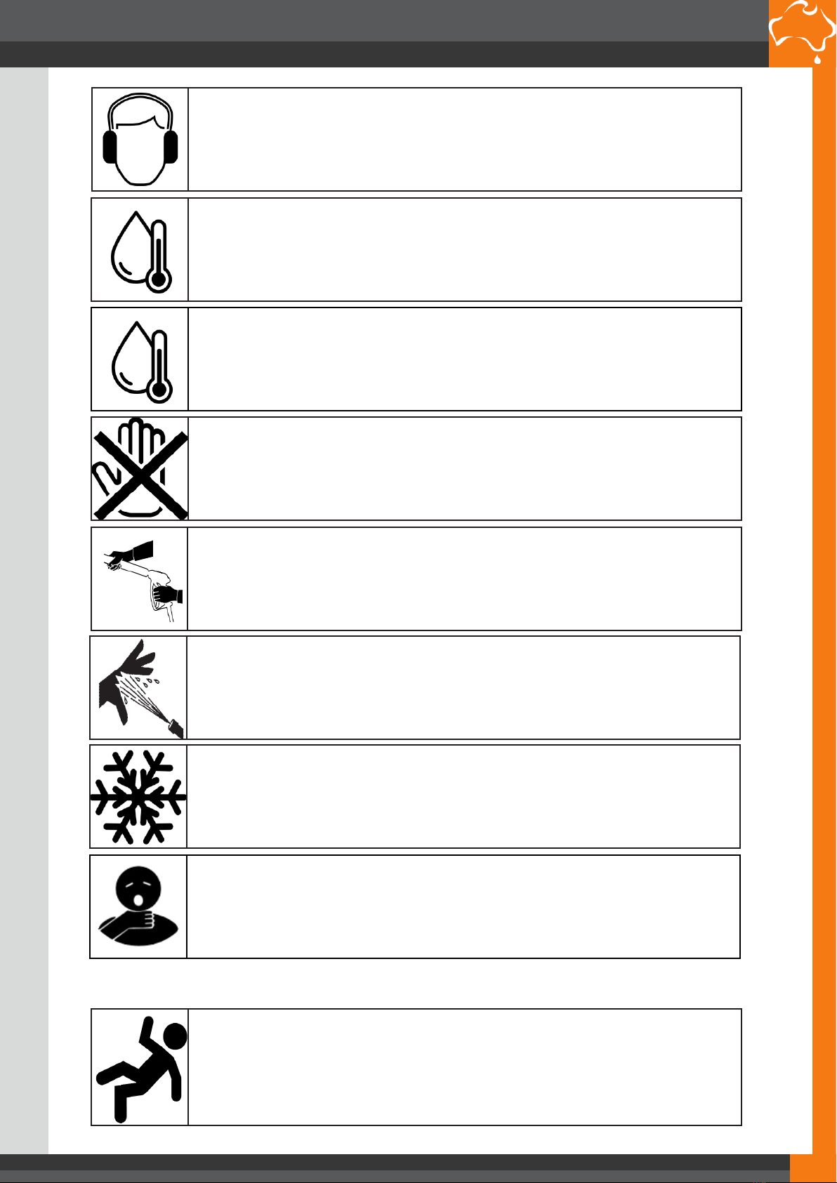
WARNING: High pressure spray can cause paint chips or other particles to become air-
borne and y at high speeds. To avoid personal injury, eye, hand and foot safety devices
must be worn.
11. Eye, hand, and foot protection must be worn when using this equipment.
PUMPS AUSTRALIAPTY LTD
COMPACT 10/120 USER MANUAL
PUMPS AUSTRALIAPTY LTD
COMPACT 10/120 USER MANUAL
PUMPS AUSTRALIA PTY LTD
2

WARNING: This machine exceeds 85 dB appropriate ear protection must be worn.
WARNING: Hot discharge uid. Do not touch or direct discharge stream at person(s)
WARNING: This machine produces hot water and must have insulated components
attached to protect the operator.
WARNING: Risk of injury. Hot surfaces can cause burns. Use only designated gripping
areas of spray gun and wand. Do not place hands or feet on non-insulated areas of the
pressure washer.
12. To reduce the risk of injury, close supervision is necessary when a machine is used near chil-
dren. Do not allow children to operate the pressure washer. This machine must be attended during
operation.
WARNING: Grip cleaning wand securely with both hands before starting. Failure to do this
could result in injury from a whipping wand.
13. Never make adjustments on machine while in operation.
14. Be certain all quick coupler ttings are secured before using pressure washer
WARNING: High pressure developed by these machines will cause personal injury or
equipment damage. Keep clear of nozzle. Use caution when operating. Do not direct
discharge stream at people, or severe injury or death will result.
WARNING: Protect machine from freezing.
15. To keep machine in best operating conditions, it is important you protect machine from freez-
ing. Failure to protect machine from freezing could cause malfunction of the machine and result in
death, serious bodily injury, and/or property damage. Follow storage instructions specied in this
manual.
WARNING: Risk of asphyxiation. Use this product only in a well ventilated area.
16. Avoid installing machines in small areas or near exhaust fans. Adequate oxygen is needed for
combustion or dangerous carbon monoxide will result.
WARNING: Be extremely careful when using a ladder, scaolding or any other relatively
unstable location. The cleaning area should have adequate slopes and drainage to reduce
the possibility of a fall due to slippery surfaces.
20. Do not overreach or stand on unstable support. Keep good footing and balance at all times.
21. Do not operate this machine when fatigued or under the inuence of alcohol, prescription
medications, or drugs.
17. Manufacturer will not be liable for any changes made to our standard machines or any components not
purchased from Pumps Australia Pty Ltd.
18. The best insurance against an accident is precaution and knowledge of the machine.
PUMPS AUSTRALIAPTY LTD
COMPACT 10/120 USER MANUAL
PUMPS AUSTRALIAPTY LTD
COMPACT 10/120 USER MANUAL
PUMPS AUSTRALIA PTY LTD
PUMPS AUSTRALIA PTY LTD 3

The machine is exclusively meant for washing and cleaning with hot and cold-water
surfaces apt to being treated with a mechanical high-pressure jet system and subject
to the eventual chemical action of detergents.
Before using the cleaner, make sure that the identification plate is fixed on the
machine; if the plate is missing, please don’t use the machine and contact
immediately your dealer (See picture. 1)
Don’t leave the machine unattended in your work environment.
After daily use, it is recommended to keep the cleaner in a dry place protected from
bad weather conditions.
Don’t use the cleaner for any other purposes than the ones described above
If you want to junk your cleaner, please follow the laws in force in your Country.
2. MACHINE IDENTIFICATION
Picture 1 below indicates where the identification plate is fixed.
The data on the plate must not be erased for any reason
3. TECHNICAL DATA
Models
120/10
15/15
17/13
Max Pressure
BAR
120
150
170
Motor power HP-RPM 3-1450 5.5-1450
5.5-1450
Absorbed Power KW 2.2 4 4
Voltage
V –Hz
230-50
400-50
400-50
Max. Flow
L/min.
10
15
13
Temperature
C
30°-120°
30°-120°
30°-120°
Fuel Tank
Lt.
15
15
15
Detergent Tank
Lt.
5
5
5
Weight
Kg.
98
98
98
4. MACHINES DIMENSIONS
PICTURE 1
PUMPS AUSTRALIAPTY LTD
COMPACT 10/120 USER MANUAL
PUMPS AUSTRALIAPTY LTD
COMPACT 10/120 USER MANUAL
PUMPS AUSTRALIA PTY LTD
4

Picture 2
5. MAIN PARTS
1 LANCE
2 HIGH-PRESSURE HOSE
3 ELECTRIC CABLE
4 ELECTRIC MOTOR
5BOILER
6 ELECTRIC WIRING BOX
7 DETERGENT TANK
8 FUEL TANK
9 TRANSFORMER
10 FUEL FILTER
11 HIGH-PRESSURE PUMP
12 PRESSURE VALVE
13 COMBUSTION HEAD
14 PRESSURE SWITCH
15 PRESSURE GAUGE
16 FULE PUMP
17 BURNER MOTOR
1
2
3
4
4
3
5
5
6
7
8
9
10
11
12
13
14
15
16
17
Picture 3
PUMPS AUSTRALIAPTY LTD
COMPACT 10/120 USER MANUAL
PUMPS AUSTRALIAPTY LTD
COMPACT 10/120 USER MANUAL
PUMPS AUSTRALIA PTY LTD
PUMPS AUSTRALIA PTY LTD 5

6. SAFETY NORMS
•Make sure that the machine is constantly supplied with water. Dry working would
cause serious damages to the cleaner seal system.
•Electrical connections must be carried out by skilled/trained personnel only.
•Wear protective glasses and garments while working.
•Never pull the power cord to disconnect the plug nor pull the hose to move the
machine.
•Don’t leave the machine in a low-temperature place and protect it from frost and
general bad weather conditions.
•Avoid vehicle transit on the high-pressure hose.
•While the machine is running do not cover it and avoid placing it where there’s low
air supply.
•If you are working indoors, it’s compulsory to install a fan to discharge the exhaust
gases outside.
•The fan terminal must not be obstructed. Don’t leave the lance or any other object
near the exhaust outlet.
•The nature of the gases as well as the high temperature need to be considered
very dangerous, the operator must thus be adequately informed to avoid being
scalded.
•Don’t leave the machine outside when it rains or when the weather conditions are
bad. The operators must wear protection clothes while using the machine.
•Don’t use the machine under the rain or in case of storms.
•Do not leave the machine for more than 5 minutes working with the gun closed,
the water temperature would increase rapidly causing serious damages to the
seal system.
•Each time the cleaner has to be switched off blow off the hose residual pressure
by using the gun.
•Don’t put the hands in front of the cleaner’s water jet while the machine is
working.
•Do not use different fuels other than the ones recommended by the manufacturer.
WARNING!
•Don’t carry out any operation on the machine before having unplugged it.
•Don’t carry out any unwary operation on the electric cable and make sure the
same is not damaged.
•Never direct the high-pressure water jet towards people, animals, electrical
installations,or the machine itself.
•Use always only clean water. Dirty water and chemical corrosive products are
harmful to the machine.
•The cleaner is equipped with idle wheels; it thus recommendable to avoid placing
the machine on ramps or slanted floors. Do not tilt the machine by more than
20°C (with a full tank).
•It is forbidden to use plug extensions if the work environment is subject to
water/humidity presence which could cut the isolating conditions of the system.
Always check the isolation of the electric cable as well as the equipment’s
integrity.
PUMPS AUSTRALIAPTY LTD
COMPACT 10/120 USER MANUAL
PUMPS AUSTRALIAPTY LTD
COMPACT 10/120 USER MANUAL
PUMPS AUSTRALIA PTY LTD
6

7. MACHINE INSTALLATION
The cleaner you are about to use will operate at it’s best if all instructions are duly
followed. Before turning on the machine, make sure it is perfectly horizontal on a
surface.
Connect the high-pressure hose A to the gun B and with the other side of the cable
to the intake fitting, fixing tightly the fastening nut C (See picture 4).
Picture 4
Connect the water supply hose D to the infeed fitting E (See picture 5). It is
recommended to use a reinforced hose having an inner diameter of at least 10mm.
The water intake must be of at least 15 l/min and have a max inlet temperature of
60°C.
Picture 5
Fill the fuel tank F (See picture 6) with Diesel.
Fill the detergent tank G (See picture 6) with a Detergent.
A
C
B
D
E
PUMPS AUSTRALIAPTY LTD
COMPACT 10/120 USER MANUAL
PUMPS AUSTRALIAPTY LTD
COMPACT 10/120 USER MANUAL
PUMPS AUSTRALIA PTY LTD
PUMPS AUSTRALIA PTY LTD 7

Picture 6
Make sure that the electrical tension and amperage are suitable for the machine. The cleaner
must be connected to a suitable feeding point equipped with an efficient contact to earth and
controlled by an overload cut out switch.
F
G
PUMPS AUSTRALIAPTY LTD
COMPACT 10/120 USER MANUAL
PUMPS AUSTRALIAPTY LTD
COMPACT 10/120 USER MANUAL
PUMPS AUSTRALIA PTY LTD
8

8. MACHINE STARTUP
After having installed the machine, to operate it, open the water supply faucet H. Picture 7.
The control panel has been designed to run the operations easily. Handgrip A has two main
functions: ON/OFF
OFF when the machine is disconnected, the second indicates that the motor pump is
running, and ON which indicates that the burner is running.
Handgrip B when turned clockwise starts the fan and while turning it again the burner starts.
Handgrip Cindicates the working pressure
Picture 7
IMPORTANT! Make sure the pressure never exceeds the
pressure indicated on the pump plate
The hydraulic system is equipped with a safety valve that works whenever the pressures are
higher than the calibration.
B
C
A
PUMPS AUSTRALIAPTY LTD
COMPACT 10/120 USER MANUAL
PUMPS AUSTRALIAPTY LTD
COMPACT 10/120 USER MANUAL
PUMPS AUSTRALIA PTY LTD
PUMPS AUSTRALIA PTY LTD 9

9. STANDARD EQUIPMENT
We suggest checking the cleaner when it is delivered. It must be complete in all the
parts and be supplied with: a thermal lance, a 10 mt high-pressure hose, and a
nozzle suitable for the model you have purchased.
10. OPTIONS
”PUMPS AUSTRALIA” supplies a rotary jet nozzle on request which allows you to
remove the hardest dirt from any surfaces you want to clean and wash.
11. DETERGENTS
It is recommended to use only liquid detergents to avoid using powder detergents.
The detergents must be biodegradable as per the laws enforced.
PUMPS AUSTRALIAPTY LTD
COMPACT 10/120 USER MANUAL
PUMPS AUSTRALIAPTY LTD
COMPACT 10/120 USER MANUAL
PUMPS AUSTRALIA PTY LTD
10

12. ELECTRICAL DIAGRAM
3
MP
5
M3 M2 M1L3 L2 L1 400 230
240
412 3400
0
230
R
S
T
P1 P2
EV
TR
MB
N
3
4
1
2
CO
TM
TOTAL STOP TRIFASE
SE
POS
DESCRIPTION
POS
DESCRIPTION
MP
Pump motor
CO
Contactor
EV
Electrovalve
SE
Electronic card
TR
High tension transformer for electrodes
P1
15 bar Pressure switch
MB
Burner Motor
P2
40 bar Pressure switch
TM
Thermostat
PUMPS AUSTRALIAPTY LTD
COMPACT 10/120 USER MANUAL
PUMPS AUSTRALIAPTY LTD
COMPACT 10/120 USER MANUAL
PUMPS AUSTRALIA PTY LTD
PUMPS AUSTRALIA PTY LTD 11

TR
MP
400
3124
L1L2 M1M2
5
P1 P2
MB
S
R
EV
TM
230
0
400
240
230
4
1
23
CO
TOTAL STOP MONOFASE
SE
POS
DESCRIPTION
POS
DESCRIPTION
MP
Pump Motor
CO
Contactor
EV
Electrovalve
SE
Electrical Card
TR
High tension transformer for electrodes
P1
15 bar Pressure Switch
MB
Burner Motor
P2
40 bar Pressure Switch
TM
Thermostat
PUMPS AUSTRALIAPTY LTD
COMPACT 10/120 USER MANUAL
PUMPS AUSTRALIAPTY LTD
COMPACT 10/120 USER MANUAL
PUMPS AUSTRALIA PTY LTD
12

13. HYDRAULIC DIAGRAM
19 20 21
1 2 9
11 10
16
43
7 6
513 12
22
17
14 15
18
8
INSTALLATION DESCRIPTION
1 –Water intake pipe
14 –Fuel intake pipe
2 –Adjustable pressure valve
15 –Fuel filter
3 –Intake pipe to boiler
16 –Fuel outlet pipe
4 –Boiler
17 –Detergent tank
5 –High-pressure hose
18 –Fuel Tank
6 –Gun
19 –Fuel Pump
7 –Lance
20 –Fan Motor
8 –By-pass Valve
21 –Fan
9 –Pressure Switch
22 –Safety Valve
10 –Pump
11 –Electrical Motor
12 –Detergent Ejector
13 –Detergent Filter
PUMPS AUSTRALIAPTY LTD
COMPACT 10/120 USER MANUAL
PUMPS AUSTRALIAPTY LTD
COMPACT 10/120 USER MANUAL
PUMPS AUSTRALIA PTY LTD
PUMPS AUSTRALIA PTY LTD 13

14. LABELS
NEW COMPACT
1 –Lance Delivery 6 –Warning! The outlet of high-pressure
exhaust gases
2 –Water feeding 7 –Type of machine
3 –Detergent Tank
8 –TOTAL-STOP / BY-PASS Model
4 –Fuel Tank
5 –Warning! Do not direct the high-pressure jet
towards people, animals or objects
WARNING!
Make sure that the stickers/labels are present on the machine and that
they are readable; if they are missing or erased, please attach or
replace them. Ask for them from the licensed dealers.
6
2
1
3
5
7
8
4
PUMPS AUSTRALIAPTY LTD
COMPACT 10/120 USER MANUAL
PUMPS AUSTRALIAPTY LTD
COMPACT 10/120 USER MANUAL
PUMPS AUSTRALIA PTY LTD
14

15. MAINTENANCE
WARNING!
•All the fixing and maintenance operations must be carried out by authorized
personnel.
•All maintenance operations must be carried out keeping the machine on an even
floor. The machine must be disconnected from the main power and the water
supply.
•A correct use and maintenance are necessary to guarantee the machine’s reliability
and it’s best performances.
•To ensure regular and constant performances it is recommended to use
original spare parts only.
•The machine you have bought has undergone a factory test which ensures correct
running at standard conditions.
•Beware! In case the cleaner has been kept inoperative for a long time, run some
water through the coil until it comes out before using it again.
Besides preliminary controls, the cleaner needs constant checks that are to be carried out
according to the following time schedules:
1) DAILY
Check the level of the oil pump utilizing the cap complete of the dipstick (See picture
3 pos. 11) If necessary add some (suggested type of oil: SAE 15W/40). The first oil
top-up must be done after 1 week's work.
Check the working condition of the feeding hose and the extension cable.
2) EVERY 2 WEEKS AND AFTER 50 HOURS WORKING SHIFT
Utilizing an air jet, clean the water filter placed in the water inlet utilizing an air
jet (See picture 5 pos. E)
3) EACH MONTH OR 100 HOURS WORKING SHIFT
Clean the combustion head (pos.13, Picture.3).
4) EACH MONTH OR 200 HOURS WORKING SHIFT
Carry out the first oil top-up of the pump as described at point 1.
Replace the fuel filter (pos.10 –picture. 3).
Clean the filter of the fuel pump (pos. 16 –picture. 3).
16. INNER COIL CLEANING
Dilute 1 Kg of a scaling product into a container filled with 10 Lt. of water. Disconnect the
water supply, remove the cover of the cleaner, pull out the intake cable from the detergent
tank, and put it into the container containing scaling product. Take the lance and remove the
nozzle, run the machine with cold water for 20 minutes. Once this operation is over, replace
the detergent intake cable into the tank and place the cover back. Connect the water supply,
run the machine by using the lance without the nozzle until the water comes out clean than fit
back the nozzle to the lance.
17. MACHINE DEMOLITION
If you want to junk your cleaner, please comply with the laws in force in your Country. The
cleaner is manufactured with parts containing recyclable metals and plastics. The oil found
inside the pump is highly dangerous and pollutant and must not be wasted in the
environment or poured into civic drains. For further information, please contact your local
committee for exhaust oil drainage.
PUMPS AUSTRALIAPTY LTD
COMPACT 10/120 USER MANUAL
PUMPS AUSTRALIAPTY LTD
COMPACT 10/120 USER MANUAL
PUMPS AUSTRALIA PTY LTD
PUMPS AUSTRALIA PTY LTD 15

Pos Qty Description
1 3 HEXAGONAL NUT M16
2 3 MEDIUM FLAT WASHER M16 ISO 7089
3 1 EXTERNAL BOILER COIL (STAINLESS STEEL OR BLACK STEEL)
4 1 INTERNAL BOILER COIL
51COIL COVER
6 1 INSULATING DISK
7 1 FLAME CONTAINMENT RING
8 1 WATER BOILER COIL (10 TO 23 LITRES)
9 1 INTERNAL BOILER FLUTE
10 1EXTERNAL BOILER COVER
11 1FUEL SUPPORTING NOZZLE
12 1 ATOMISATION FUEL NOZZLE WITH FILTER
13 1 NOZZLE HOLDER
14 1 INSPECTION BOILER GLASS
15 1 CIRCLIP RING
16 1 BOILER MOUNTING PLATE
17 1 ELECTRODES CABLES 11,000 VOLTS (240VAC SYSTEM)
17A 1 ELECTRODES CABLES 22,000 VOLTS (12VDC SYSTEM)
19 1 DOUBLE ELECTRODE COVER
20 1COPPER FUEL LINE ELBOW
21 1 COPPER FUEL SUPPLY LINE
22 1 COPPER FUEL LINE CONNECTOR
23 1 DUAL ELECTRODES
24 1 240VAC / 24VAC FUEL SOLENOID
24A 1 12VDC FUEL SOLENOID
25 1FUEL SUPPLY LINE FITTING
26 1 DIESEL FUEL PUMP
27 1 FUEL PUMP ADAPTOR
28 1 240VAC BURNER MOTOR
28A 1 12VDC BURNER MOTOR
29 1 FAN BLADE (LEFT ROTATION)
29A 1 FAN BLADE (RIGHT ROTATION)
30 1240VAC IGNITION TRASFORMER
30A 112VDC IGNITION TRANSFORMER
PUMPS AUSTRALIAPTY LTD
COMPACT 10/120 USER MANUAL
PUMPS AUSTRALIAPTY LTD
COMPACT 10/120 USER MANUAL
PUMPS AUSTRALIA PTY LTD
16

1
2
3
4
5
6
7
8
9
19
10
11
12
13
14
15
16
17
18
19
20
21
22
23
24 25 30
26
27
28
29
Quick Selection Legend
Outer Casing
Fan System
Solenoid & Fuel Pump System
Transfomer
Inner Coil Assembly
Boiler Pad
Fuel System
Electrical System Please Note: 240VAC Option Shown, 12VDC will vary.
PUMPS AUSTRALIAPTY LTD
COMPACT 10/120 USER MANUAL
PUMPS AUSTRALIAPTY LTD
COMPACT 10/120 USER MANUAL
PUMPS AUSTRALIA PTY LTD
PUMPS AUSTRALIA PTY LTD 17

PUMPS AUSTRALIA PTY LTD
PUMPS AUSTRALIAPTY LTD
PARTS BREAKDOWN
96
UN003304-MR
78
88
36
502 32 49 47 48
44 45
37
38
77
39
19
41
17
134
56
4
3
1
2
1112 13
14 15 16
18
21
25
28
30 34
29
27 31
23
26
24
40
19
20
17
46
42
22
42
43
35
89
87 86
43
42
@
UN003305-AS
CC
AA
A
A
GE
EEC
B
C
C
KIT RICAMBI / PART KITS
RK
N1450rpm ø 24x30 mm
(2288600)
sp_00500_RK_N
PUMPS AUSTRALIAPTY LTD
COMPACT 10/120 USER MANUAL
PUMPS AUSTRALIAPTY LTD
COMPACT 10/120 USER MANUAL
PUMPS AUSTRALIA PTY LTD
18

PUMPS AUSTRALIA PTY LTD
PUMPS AUSTRALIAPTY LTD
PARTS BREAKDOWN
97
SIMBOLOGIA - SYMBOLSKIT RICAMBI - PART KITS
228 Series
RK 1450 rpm N version ø 24 mm
11.14 (20630) 13.17 (20634) 15.15 (20637) 15. 20 (20897) (FC) 18.20 H (20643) 21.15 (20645) 18.16 H (FP)
11.20 H (20631) 13.20 H (20635) 15.20 H (20638) 15.28 H (20640) 18.28 H (21467) 21.20 H (21129)
11.25 H (20632) 14.16 (20636) 15.25 H (20639) 18.12 (20641) 21.10 (20644) 13.12 (FP)
PARTI SPECIALI IN VITON SPECIAL PARTS
Cod. - Part n° Denominazione - Description Q.tà - Q.ty
2809 Tenute acqua/Water seals ø 18 1
2810 Tenute acqua/Water seals ø 20 1
2811 Tenute acqua/Water seals ø 22 1
A=KIT 2864
valvole
valves
pistoni
pistons
B=KIT 2757 ø 18
B=KIT 2758 ø 20
B=KIT 2759 ø 22
C=KIT 1855
tenute olio
oil seals
Pos. Q.ty Pos. Q.ty Pos. Q.ty
3 6 25 316 3
4 6 19 2
34 1
39 1
tenute acqua
water seals
E=KIT 1857 ø 18
E=KIT 1887 ø 20
E=KIT 1888 ø 22
anelli appoggio
support rings
G=KIT 1829 ø 18
G=KIT 1815 ø 20
G=KIT 1816 ø 22
Pos. Q.ty Pos. Q.ty
12 311 3
14 3
15 3
❍ Per / For
RK 11.14 cod. 20630
RK 11.20 H cod. 20631
RK 11.25 H ☞ cod. 20632
❒ Per / For
RK 13.12
RK 13.17 cod. 20634
RK 13.20 H cod.
20635
● Per / For
RK 14.16 cod. 20636
✪ Per / For
RK 15.15
cod. 20637
RK 15.20
cod. 20897
RK 15.20 H cod. 20638
RK 15.25 H ☞ cod. 20639
RK 15.28 H ☞ cod. 20640
✩ Per / For
RK 18.12 cod. 20641
RK 18.16 H
RK 18.20 H cod. 20643
RK 18.28 H ☞ cod. 21467
★ Per / For
RK 21.10
cod. 20644
RK 21.15 H
cod. 20645
RK 21.20 H
cod . 21129
C Tolleranza coppia di serraggio +0÷-10% / Tightening torque tolerance +0÷-10%
Avvitare con Loxeal 55-14 / Screw with Loxeal 55-14
(b) Montare anello tenuta con attrezzo cod. 2281010 / Fit the seal with tool code nr. 2281010
☞
OLTRE 250 bar - OVER 3600 psi
@ Posizionamento targa di identicazione / Identication plate positioning
Olio - Oil
Tipo / Type Quantità / Quantity
SAE 15W40 0,435 Kg
Pos. Cod. Denominazione Description Qt Note
1960160 Guarnizione OR Ø 17,86x2,62 O-ring 6
2
960090 Tappo Plug 6RK C=54Nm
960850 Tappo Plug 6
RK H ☞C=54Nm
1380740 Tappo Plug 6RK H C=54Nm
31389051 Valvola completa Complete valve 6
4 880830 Guarnizione OR Ø 15,54x2,62 O-ring 6
5
880581 Tappo 1/4" G Plug 2 RK C=15Nm
1380690 Tappo 1/4" G nickel Plug 2
RK H - H ☞ C=15Nm
6820510 Guarnizione OR Ø 10,82x1,78 O-ring 2
11
960110 Anello appoggio Ø 18 Ring 3❍ ❒ ● ✪
840300 Anello appoggio Ø 20 Ring 3✩
840320 Anello appoggio Ø 22 Ring 3★
12
1382740 Tenuta acqua Ø 18 Water seal 3❍ ❒ ● ✪
840290 Tenuta acqua Ø 20 Water seal 3✩
840330 Tenuta acqua Ø 22 Water seal 3★
13
1380090 Guida pistone Ø 18 Piston guide 3❍ ❒ ● ✪
1380150 Guida pistone Ø 20 Piston guide 3✩
1380160 Guida pistone Ø 22 Piston guide 3★
14 961240 Guarnizione OR Ø 31,47x1,78 O-ring 3
15
880330 Tenuta acqua Ø 18 Water seal 3❍ ❒ ● ✪
840280 Tenuta acqua Ø 20 Water seal 3✩
840340 Tenuta acqua Ø 22 Water seal 3★
16 1383130 Anello tenuta Ring 3
17 850370 Vite TCEI M8x16 Screw 8C=24,5Nm
18 1380050 Supporto
cuscinetto chiuso
Support 1
19 640030 Guarnizione OR Ø 59,99x2,62 O-ring 2
20 2280340 Cuscinetto Bearing 1
21 1382770 Corpo pompa Pump body 1
22 880130 Tappo Plug 1
23 962010 Dado Nut 3C=20Nm
24 962000 Rondella Washer 3
25
1380940 Pistone Ø 18 Piston 3❍ ❒ ● ✪
1380930 Pistone Ø 20 Piston 3✩
1382360 Pistone Ø 22 Piston 3★
26 1380950 Disco Plate 3
27 600180 Guarnizione OR Ø 7,66x1,78 O-ring 3
28 1380920 Pistone di guida Piston 3
29 1380060 Spina Pin 3
30
1383050 Biella alluminio Connecting-rod 3
1383020 Biella bronzo Connecting-rod 3
31 1080401 Anello antiestrusione Ring 3
32 1381850 Rondella Washer 8
Pos. Cod. Denominazione Description Qt Note
34 1780510 Guarnizione OR Ø 106x3 O-ring 1
35 1789010 Coperchio completo Cover 1
36 1343510 Vite TCEI M6x14 Screw 6C=10Nm
37
2280100 Albero marcato 5 Shaft 1❍
2280080 Albero marcato 3 Shaft 1❒
2280070 Albero marcato 2 Shaft 1●★
2280060 Albero marcato 1 Shaft 1✪ ✩
38 1380520 Linguetta Key 1
39 180340 Anello tenuta Ring 1(b)
40
1380120 Spessore 0,10 mm Shim 0.10 mm 1÷3
1380130 Spessore 0,19 mm Shim 0.19 mm 1÷3
1380530 Spessore 0,25 mm Shim 0.25 mm 1÷3
1382810 Spessore 0,05 mm Shim 0.05 mm 1÷3
41 1380040 Supporto
cuscinetto aperto
Support 1
42 740290 Guarnizione OR Ø 14x1,78 O-ring 3➌
43 1980740 Tappo 3/8" G ottone Plug 2➌ C=20Nm
44 1263130 Vite TE M8x12 Screw 4
Optional C=20Nm
45 1380141 Piede Foot 2Optional
46
1980740 Tappo 3/8" G ottone Plug 1RK C=25Nm
1981180 Tappo 3/8" G nickel Plug 1
RK H - H ☞ C=25Nm
47 180101 Guarnizione OR Ø 17,5x 2 O-ring 1
48
820361 Tappo 1/2" G ottone Plug 1RK C=40Nm
960870 Tappo 1/2" G nickel Plug 1
RK H - H ☞ C=40Nm
49
1381071 Testa Head 1Ø18 RK
1381070 Testa nikelata Head 1
Ø18 RK H - H ☞
1380020 Testa Head 1Ø20-22 RK
1380680 Testa nikelata Head 1 Ø20-22 RK H
50 820150 Vite TCEI M8x70 Screw 8C=24,5Nm
77 1383140 Cuscinetto Bearing 1
78
1389270
Premontaggio testa
Head assembly 1Ø18 RK
1389272
Premontaggio testa
Head assembly 1 Ø18 RK H
1389271
Premontaggio testa
Head assembly 1 Ø18 RK H ☞
1389208
Premontaggio testa
Head assembly 1Ø20 RK
1389212
Premontaggio testa
Head assembly 1 Ø20 RK H
1389216
Premontaggio testa
Head assembly 1Ø22 RK
1389220
Premontaggio testa
Head assembly 1 Ø22 RK H
86 1260250 Indicatore livello Level gauge 1 ➌
87 1260430 Anello Ring 1➌
88 1780690 Disco Plate 1➌
89 1140450 Guarnizione OR Ø 20,24x2,62 O-ring 1➌
➌Compreso nel cod. 1789010 / Part of part n° 1789010
MI 91423 (3056) (2322) (2990)DI_1388523
PUMPS AUSTRALIAPTY LTD
COMPACT 10/120 USER MANUAL
PUMPS AUSTRALIAPTY LTD
COMPACT 10/120 USER MANUAL
PUMPS AUSTRALIA PTY LTD
PUMPS AUSTRALIA PTY LTD 19

18. DRAWBACKS, CAUSES, AND SOLUTIONS
IRREGULARITIES
POSSIBLE CAUSES
SOLUTIONS
WATER DOES NOT
COME OUT
Dirty water filter
Blocked infeed valves
Clogged lance nozzle
Clean or replace
Check
Clean
WEAK OR
IRREGULAR
PRESSURE
The detergent valve is open and takes
in air
Insufficient water supply
The pump intakes air
Worn out valve
Worn out/not suitable nozzle
Worn out gaskets
Exceeding water temperature
Encrusted coil
Check
Check the capacity
Check
Replace
Replace
Replace
Check
Scale
THE BURNER DOES
NOT TURN ON
Excessive air intake
Dirty fuel filter
Dirty fuel pump filter
Dirty burner nozzle
Faulty thermostat
Broken/blocked electrovalve
Insufficient electrodes spark
Defected flowmeter and/or pressure
switch
Worn out motor pump joint
Absent/insufficient voltage
Check
Replace
Clean or replace
Replace
Replace
Replace
Replace
Replace
Replace
Check
NOISY CLEANER
Air intake;
Worn out/dirty/blocked valves;
Exceeding water temperature
Check the intake
pumps
WATER PRESENCE
IN THE OIL
Worn out water/oil rings
The high percentage of humidity in the
air
Replace
Check
OIL LEAKAGE FROM
THE HEAD
Worn out O-rings of the seal system
Replace
MOTOR DOES NOT
START WHEN
PRESSING THE
SWITCH
The plug is not working due to
overheating
Check the plug, the
cable,and the
ON/OFF switch
SUDDEN MOTOR
STOP
The thermal protection is not working
due to overheating
Make sure that the
tension is suitable
TROUBLE SHOOTING
PUMPS AUSTRALIAPTY LTD
COMPACT 10/120 USER MANUAL
PUMPS AUSTRALIAPTY LTD
COMPACT 10/120 USER MANUAL
PUMPS AUSTRALIA PTY LTD
20
This manual suits for next models
2
Table of contents
Other Pumps Australia Water Pump manuals
Popular Water Pump manuals by other brands

Pentair
Pentair MYERS MS33PT owner's manual

MELAG
MELAG ME65010 installation instructions

Vim Solution
Vim Solution Aria Operation manual

Polaris
Polaris TBM 150 MH Series Installation, operation and maintenance manual

Pompetravaini
Pompetravaini TCHM Series Disassembly & Assembly Instructions

Q-sense
Q-sense E1 Setup

Dover
Dover PSG ALL-FLO A050 Installation operation & maintenance

Heritage
Heritage 1021 Service manual

coolado
coolado tPump P instruction manual

GORMAN-RUPP PUMPS
GORMAN-RUPP PUMPS 10 16C2-F5L Series Installation, operation, and maintenance manual with parts list

Acquaer
Acquaer SJC050 owner's manual

Graco
Graco Triton 308 Instructions-parts list