Pure H2O QUATREAU 553-B User manual

BOILING CHILLED SPARKLING HOT & COLD
Touch
INSTALLATION,
COMMISSIONING
AND USER GUIDE

————————————————————
CONTENTS
INSTALLATION,
COMMISSIONING
AND USER GUIDE
————————————————————
PRE-INSTALLATION CHECK LIST
SECTION ONE
INSTALLATION
• UNPACKING YOUR EQUIPMENT
• INSTALLING THE TAP
• INSTALLING THE QT553-B (boiler control module)
• INSTALLING THE C20 CS20 C50 & CS50 (Chiller or Chiller Carbonator range)
• SYSTEM DETAILS
• PIPEWORK, VENTILTION & POWER REQUIREMENTS
• IMPORTANT INFORMATION
SECTION TWO
COMMISSIONING
• COMMISSIONING THE QT553-B
• COMMISSIONING THE C20/CS20/C50/CS50
SECTION THREE
USER GUIDE
• INTRODUCTION
• TOUCHSCREEN
• CHILLER CARBONATOR (C20/CS20/C50/CS50)
• TAP FUNCTIONS
• FAQS
• IMPORTANT INFORMATION
• CUSTOMER SATISFACTION NOTE
CONTENTS

———————————————————————————————--------—————————
QUATREAU TOUCH
PRE-INSTALLATION CHECK LIST
———————————————————————————————--------—————————
1. Correct sized hole drilled in worktop i.e. 40mm
2. Mains Cold Water: 1/2” lever ball valve, locatied top front right side wall
of cupboard, set back 15 cm from door, 50 cm up from base.
3. Thermostatic Valve to be installed so that it is accessible for adjustment
on the same side of the cupboard asthe mains cold water supply. Note
that this is in addition to the isolated Mains Cold Water that will be used
to feed a cold supply to the system.
4. Drainage: Trapped upstand, located back left hand side of cupboard
taking care not to sterilise the floor space within cupboard, ensure you have an
approved type AA fitting.
5. Power: Type 2 x 13amp single or one double socket if ordering models 353, 453-B
or 553-B, located front left wall of cupboard, 50 cm up from base.
———————————————————————————————--------—————————
QUATREAU TOUCH
TYPICAL INSTALLATION
———————————————————————————————--------—————————
PRE INSTALL CHECK LIST

————————————————————
SECTION ONE
UNPACKING YOUR EQUIPMENT
————————————————————
Your systems has been carefully
packaged. If the box is damaged upon
delivery you should photograph the
damage and remove the contents for
inspection before signing the delivery
note. Equipment delivered by shipping
agents or couriers must be insured by
the client. They are not insured once they
leave our premises in Woking, nor will we
be liable for damage in transit
STEP 1
Remove and inspect tap, open top layer
of foam and inspect the Quatreau tap
for signs of damage. Remove the tap
in its protective layer and put on a flat
surface where it cannot be damaged
accidentally.
STEP 2
Remove and inspect Q553-B
The Q553-B sits on a soft layer of foam.
On top you will see two opaque stems
sticking up. Be careful not to damage
these outlets. The unit weighs 19.8Kg so be
careful to use the correct lifting procedure
(knees bent back straight) to avoid hurting
yourself. If in doubt, seek advice before
lifting.
Cut down each side of the box to reveal
the system so that you don’t have to lift it
upwards, out of the box. Carefully place
one hand under the front lip of the system
next to the filter, this will give you a firm
hold and leverage.
Tilting the system away from you, place
your other hand under the base of the
opposite end. This will ensure you have
control of the weight when you lift.
Remove from box and place in on the
floor.
————————————————————
WARNING: THE EDGES ARE
HARD STAINLESS STEEL AND
CAN DAMAGE CUPBOARD
DOORS OR FURNITURE, HANDLE
WITH CARE.
————————————————————
STEP 3
Check the installation equipment and
electrical connection that will be in a
plastic bag inside the packing. A contents
list will explain what should be included
and what the parts are used for.
————————————————————
PRIOR TO INSTALLATION WE
RECOMMEND THAT YOU
REVIEW THE PRE-INSTALLATION
GUIDE SENT OUT BEFORE YOU
PURCHASED THE EQUIPMENT.
THIS PROVIDES ALL THE
INFORMATION REQUIRED FOR
A SUCCESSFUL INSTALLATION.
IF YOU DO NOT HAVE THIS VISIT
OUR WEBSITE WWW.PUREH2O.
CO.UK AND LOOK FOR
DOWNLOADS IN THE QUATREAU
TAPS SECTION.
————————————————————
SECTION TWO
INSTALLING THE QUATREAU TAP
————————————————————
Before we start installing the tap (faucet)
be sure to think through the installation.
IN STA LL AT IO N

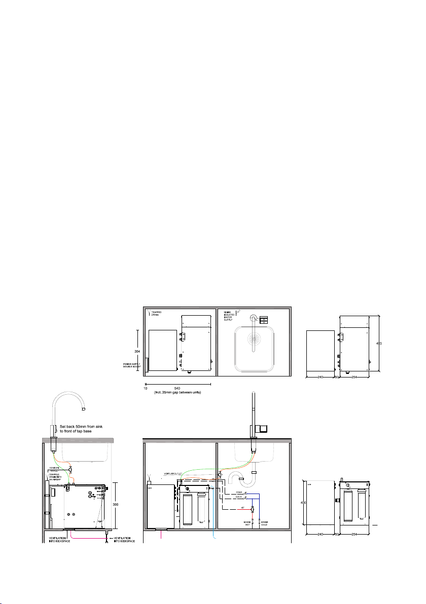
The Boiler control units and Chiller
Carbonator modules must sit underneath
the tap or in an adjacent cupboard to the
tap location.
This is because the tap has a
communication cable that plugs into
the Q553-B (boiler control) that cannot
be stretched. Most models will fit into
a standard 600 cupboard. The Infinite
range(653) requires a 650 or 700
cupboard as minimum space.
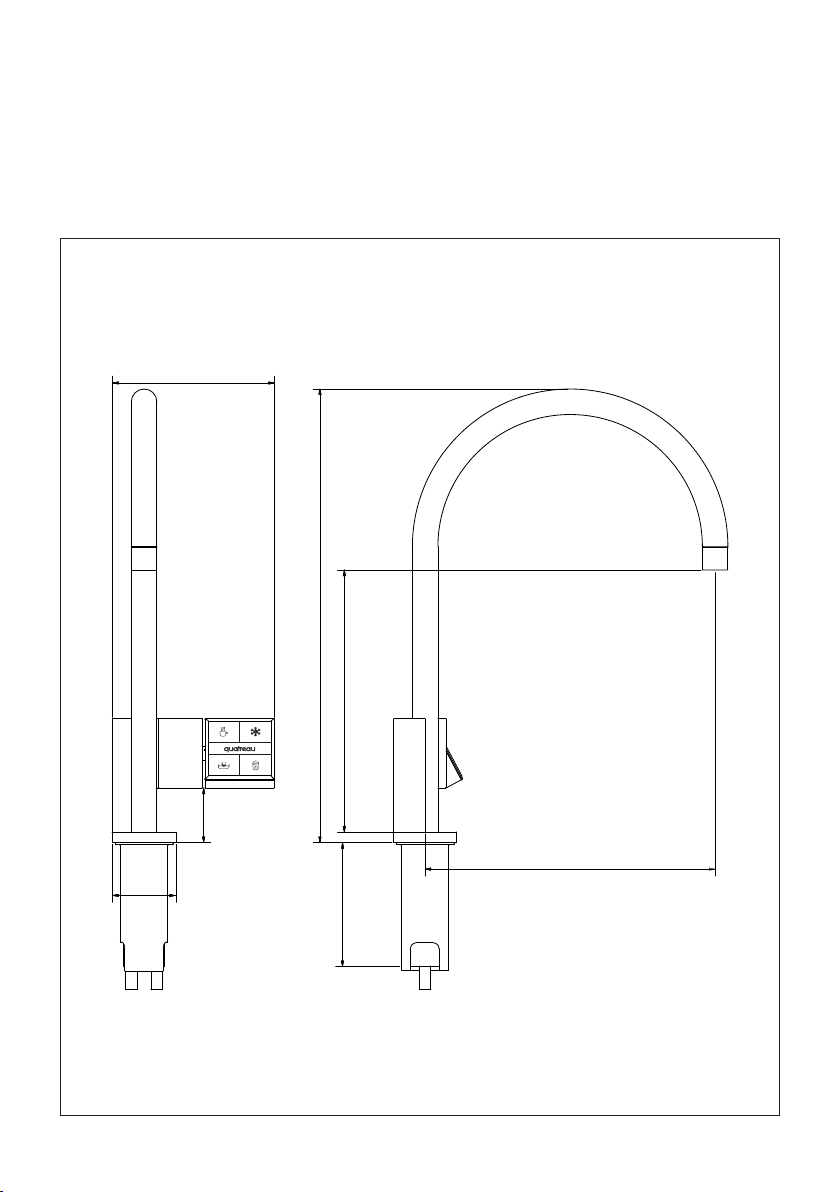
There are 3 types of Quatreau Tap (faucet)
1. Quatreau Touch™
2. Quatreau SmartTap™*
3. Quatreau SmartTap™ with integrated
driptray*
1. INSTALLING THE QUATREAU TOUCH™
The Touch requires a 40mm hole cut into
the surface behind the sink or drainer it is
going to be used with.
Depending upon the surface you will
need special cutting equipment. For
granite or marble a diamond tipped
core bit will be required. For wood or MDF
or polymer type surface a wood bit will
normally be adequate. Always check with
the worksurface manufacturer and ask
what type of bit can be used.
Decide where the tap is going to sit. Note
that the control panel is on the right-hand
side of the tap. Ensure that the location
you choose is suitable and that you can
reach the controls without needing to
stretch.
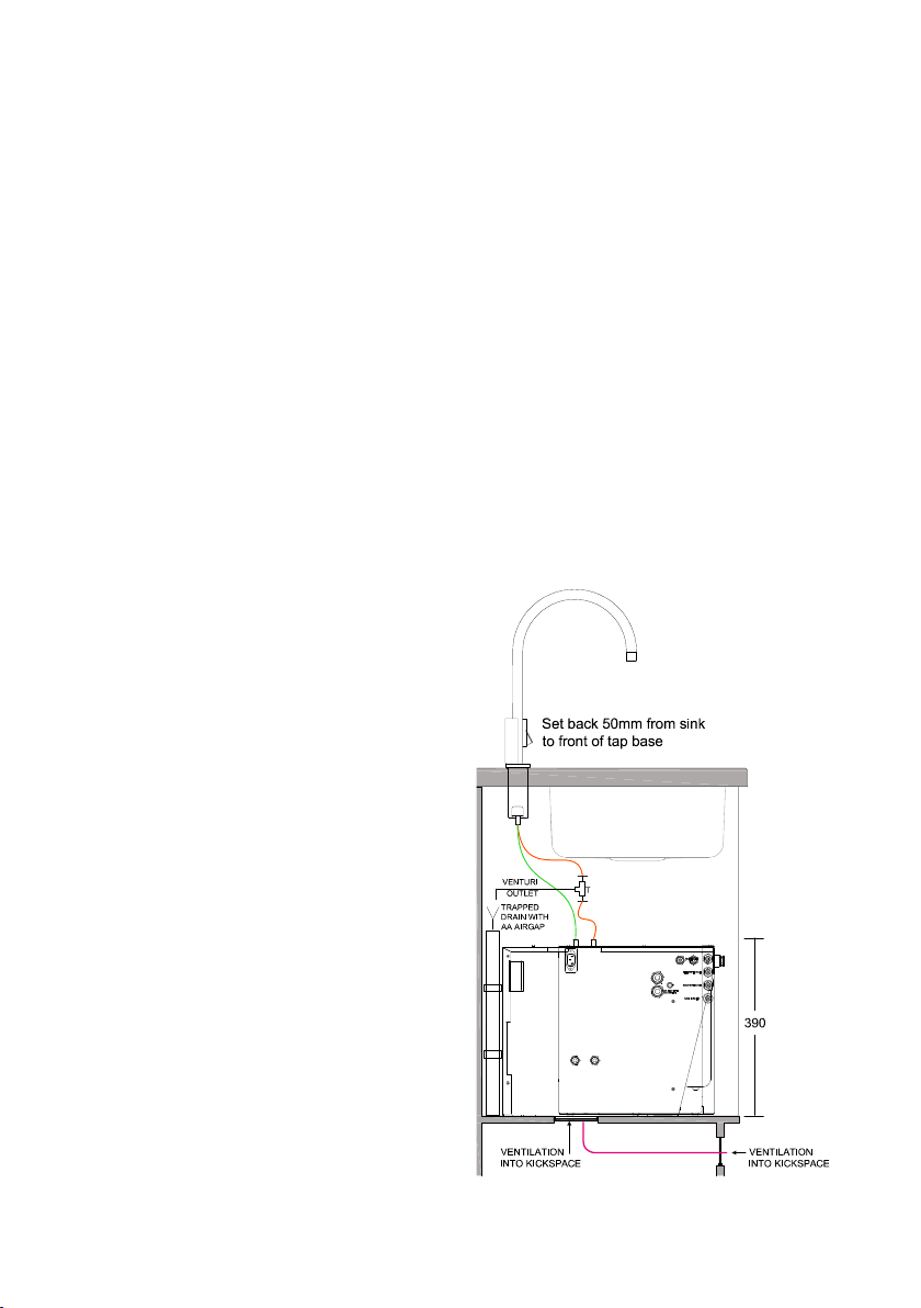
We typically set back approximately
50mm from the back edge of the sink.
Your kitchen design will of course dictate
whether this is possible.
Before you start cutting ensure that you
have set up a jig or a template device to
prevent the drill bit moving when you start
the cut.
Once the hole is prepared, remove any
rough edges or bits of wood and place
the tap carefully into the hole ensuring
that the comms cable is dropped into the
hole first to prevent damage.
Using the washer and fixing bracket
provided, you can now fix the tap in
place underneath the work surface.
Be careful to locate the comms cable
into the groove behind the tap base
then slide the washer up over the base
followed by the fixing bracket. This will
screw onto the thread on the tap base.
Ensure that the comms cable is not
damaged as you spin the bracket
clockwise until it is almost at the top of the
thread.
At each side of the fixing bracket you will
see a threaded hole. Using the two bolts
provided thread up into these holes until
tight against the washer above. With a
flat head screw driver, tighten each one
gently.
Now position the tap so that the control
panel faces forward towards the user
position (180degrees to the sink). Now you
can tighten the nuts until you have a firm
fixing on both sides.
The comms cable hangs down and will
connect into the QT553-B unit when it
is installed. It’s essential that the 553-B
is located close to this cable without
causing it to stretch.
*See the Quatreau SmartTap version™of this document for installaiton details.
IN STA LL AT IO N

————————————————————
QUATREAU TOUCH
INSTALLING YOUR TAP
————————————————————
Once the point of installation is ready to
recieve Quatreau and a 40mm hole has
been drilled in to the worktop in which
the tap is to be installed installation can
begin.
1. Insert the tap in to the hole in the
worktop
2. Ensure that the control cable sits
inside the groove along the side of
the tap body
3. The nut that screws onto the base
of the tap should have two bolts
inserted into the wing. To fix the tap
in place push the plain washer on
first taking care not to damage the
communication cable by keeping
the cable in the grove. Next thread
the nut onto the thread of the tap
again taking care not to damage
the comms cable by keeping it in
the groove. Once the nut is almost
at the top of the under side of the
worktop use the two bolts to take up
the slack between the washer and
the nut. Using a flat head screwdriver
to tighten the bolts, you will pull the
tap down onto the work-surface and
create a tight fit. Do not over tighten,
once the tap is firmly in place stop.
Your tap is now fixed in place.
4. Connect two lengths of platinum
cured silicon tube from the fitting kit
to the tap stems on the underside of
the tap. Fix in place using the spring
loaded clamps included in the fitting
kit. Avoiding kinks make a clean run
to the top of the 553-B and fix the
other ends to the manifold outlet
stems protruding from the top of the
553-B as follows:
5. The rear manifold stem is the mains
unfiltered water. This connects to the
left hand stem of the tap as you look
at it inside the cupboard.
6. The purified outlet is the front most
stem from the manifold on top of the
553-B. This connected to the right
hand stem as you look at it.
7. Between the pure outlet and the tap
install the Venturi T supplied in the
installation kit. On the smaller side T
run a pipe to a type AA (air gap) drain
connection. This is to allow expansion
from the boiler to run to drain. See
picture below
IN STA LL AT IO N

————————————————————
DO NOT TURN THE POWER ON
TO YOUR SYSTEM UNTIL YOU
HAVE READ THROUGH THE
COMMISSIONING STAGES IN THE
NEXT SECTION. POWERING UP IS
PART OF THE COMMISSIONING
SEQUENCES. DAMAGE MAY
OCCUR IF YOU FAIL TO FOLLOW
IT CAREFULLY.
————————————————————
QUATREAU TOUCH
INSTALLING THE QT553-B
————————————————————
STEP 1
Install the Thermostatic valve in
accordance with instructions, onto
the hot and cold mains. Using the John
Guest 1/2” - 3/8” reducer included in your
instillation kit, connect to the temperature
controlled outlet port (this will maintain
temperature at or below 42C).
Using the 3/8” blue pipe enclosed cut a
length to feed the hot mains water inlet on
the left side of the QT553-B module.
As part of this installation you will also
install a separate cold water supply with
a 1/2” isolation valve. This will control the
cold water mains feed to the left and the
smaller 1/4” cold feed into the front right
hand side of the QT553-B.
Connect a John Guest 1/2” -3/8” reducer
to this cold isolation valve and run a length
of blue 3/8” PE pipe ready for connection
to the cold mains water inlet alongside the
hot water inlet.
To create the secondary cold inlet feed
connect the 3/8” reducing T into the same
3/8” pipe at the closest point to isolator
and run a length of 1/4” pipe to the pure
inlet on the right hand side of the QT553-B.
Also connect the 1/4” isolation valve just
before the inlet. This will be sued for control
purposes.
STEP 2
With the QT553-B (boiler control module)
module on the right hand side of the
cupboard connect the thermostatic hot
and the mains cold connections using
the 3/8” blue PE pipe enclosed in your
installation kit.
Attach the blue 3/8 pipe enclosed to the
3/8 ports at the back left hand side of the
unit. Note that hot is furthest to the back
and cold is attached in front of the hot.
Both ports are laser etched hot / cold. Turn
both the hot and cold services until 50%
open. These connections feed a robust,
one piece manifold. Whilst a water tight
seal should be instantly achieved with the
push fittings, its important to observe and
listen for any water escaping.
The manifold is very robust and should
cope with transit but, in the event of the
system being dropped damage may
occur. In this event call your supplier and
request a new 553 manifold.
Now connect the cold water feed to the
top front right hand side of the 553-B.
using the 1/4” PE pipe provided. The speed
fitting will make a water tight seal when the
pipe is pushed firmly into the port labeled
PURE INLET. Note that this can be fed by a
purifier or mains cold water.
If using a purifier to feed the system ensure
it has been commissioned with a 50psi
IN STA LL AT IO N

deact switch prior to connection. You will
use several litres of water to commission
the Quatreau system so it is sensible to
commission with mains water first then
convert to pure once the system has been
purged.
————————————————————
QUATREAU TOUCH
INSTALLING THE C20/CS20/C50/CS50
————————————————————
Before installation of the chiller unit, refer
to the cutting template enclosed with the
chiller. A ventilation hole is cut in the base
of the cupboard and the vent pipe run
to and cut into the kick board using the
ventilation grill provided.
See Pre-Installation guide for more
information.
Ventilation will ensure your chiller performs
to its specification. Failure to install this will
void the warranty on this module.
The Quatreau chiller carbonator is sited
next to the 553-B (control unit). Usually this
will be to the left of the 553-B.
Using the 1/4” PE pipe provided take a
feed from the pureh2o outlet and connect
it to the pureh2o inlet on the front of the
chiller
Do the same for the CO2 (gas connection)
repeat the process with the two remaining
ports;
The chilled outlet connects to the CHILLED
IN on the left hand side of the 553-B
The CARB (sparkling) outlet connects to the
CARB IN just above the CHILLED IN port
Ensure that you leave a 10-20mm gap
around the sides of the chiller unit - this
enables ventilation and air movement
without which the system will not chill
correctly.
IN STA LL AT IO N

250
226
140
391
55
107
47
————————————————————
SYSTEM DETAILS:
QUATREAU TOUCH
Note:
Requires 40mm diameter hole in counter
top positioned minimum 50mm back from
the edge of the sink.
IN STA LL AT IO N

————————————————————
INSTALLATION
PIPEWORK REQUIREMENTS
Quatreau Touch delivers unfiltered hot
and cold mains water for washing. The
hot supply comes directly from the
thermostatic valve installed on the hot
water services of the building. Typically
in the same cupboard where the
equipment will be sited.
Mains hot and cold services must have
isolators fitted.
The thermostatic valve should be fixed
to the side of the cupboard in which
the QT553-B or C20/CS20/C50/CS50 is
to be installed. Ensure that both the hot
and cold valves are fixed that permits
access to adjust flow rate, temperature or
isolation. The braided hoses screw on to
the 1/2” fitting on the thermostat and the
1/2” isolation valve for the cold water.
NOTE:
An appproved thermostatic mixing valve
must be fitted.
IN STA LL AT IO N

————————————————————
INSTALLATION
VENTILATION REQUIREMENTS
It is recommended that a trickle vent is
cut into the top of the cupboard in which
the Quatreau 553-B and Quatreau Chiller/
Chiller Carbonator C20/CS20/C50/CS50
sits.
All chiller and chiller carbonator units must
vented adequately. A vent kit should be
purchased with each system. Ventilation
is cut into the base of cupboard under
the chiller and a duct run to the kick
board. The kickboard is also cut to permit
air to be drawn into the duct and a grille
provided.
————————————————————
INSTALLATION
POWER REQUIREMENTS
2 x 13A sockets.
Note:
For new kitchens a separate fused feed is
required for the Quatreau 553, Quatreau
Chiller/Chiller Carbonator C20/CS20/C50/
CS50.
IN STA LL AT IO N

IMPORTANT INFORMATION
TECHNICAL DETAIL QUATREAU 553-B QUATREAU CHILLER/CHILLER CARBONATOR
POWER REQUIREMENTS 1 x 13A socket 1 x 13A socket / 1 x 13A socket
(RCD Protected)
VOLTAGE 230V 230V / 230V
WATTAGE
Max consumption 2.56KW 130W / 296W
Standby consumption 80W 130W / 100W
START UP TIME 10 minutes 10 minutes
MAX WORKING PRESSURE 3Bar 3Bar
CO2 CAPACITY 100ltrs carbonated water
INSTALLATION DETAIL BY AUTHORISED PURE H2O TECHNICIAN ONLY
INSTALLATION DATE
INSTALLATION NOTES
CONTACT CUSTOMER SERVICE
01483 617000
customerservice@pureh2o.co.uk
IN STA LL AT IO N

————————————————————
QT-553B
COMMISSIONING SEQUENCE
————————————————————
DO NOT POWER THE SYSTEM UP
UNTIL SECTION D STEP 3.
————————————————————
SECTION A:
Connections from QT-553B to Quatreau
Touch tap
1. Connect (platinum cured) silicon 3
mm wall thickness from the front
outlet of the QT-553B to the right hand
side of the tap as you look at it panel
facing forward.
2. Connect (platinum cured) silicone 3
mm wall thickness from the back
outlet of the QT-553B to the left hand
side of the tap as you look at it panel
facing forward.
3. Secure top fittings using the spring
loaded clips
4. Secure bottom fitting (outlet on top)
using the black compression clips
5. Ensure the silicon pipe is not kinked or
too long and ensure it flows in a nice
manner that will avoid back pressure
into the QT-553B. Back pressure will
cause the pipe to burst. The pipe
should fit without being stretched or
too long.
—————————————————
SECTION B:
Connections for Mains Hot & Cold water
1. Connect mains hot and cold pipe to
the Thermostatic valve.
2. Adjust thermostat to the hottest
setting and turn back ½ turn
3. Take the feed from the warm outlet
(40degreesC) and connect (using the
braided hose provided) to the 3/8”
mains hot elbow inlet on the side of
the QT-553B.
4. Connect the other braided hose to
the cold mains water supply and fit to
the cold mains 3/8” inlet elbow on the
side of the QT-553B.
5. Connect a supply of cold mains
water through the ¼” pipe work
provided into the top right inlet on the
QT-553B marked “pure inlet”.
6. Gradually open the supply of hot and
cold water checking that the fittings
are water tight.
————————————————————
SECTION C:
Interconnections QT553-B to Chiller
Carbonator
1. Connect the interconnections of
water and gas from the QT553-B or
chiller carbonator module C20/CS20/
c50/CS50.
a. ‘CO2 out’ to ‘CO2 inlet’ on the
chiller front,
b. ‘H2O out’ to ‘H2O inlet’ on the
chiller front. install a 1/4” isolator
into this line feeding into the
chiller and turn it off. This is an
important step in commissioning.
c. ‘carb out’ on chiller to sparkling
(carb) inlet on QT-553B,
d. ‘chilled out’ on chiller back to
chilled inlet on QT-553B
2. Gradually open the mains water
supply to the ¼” “pure inlet”. Check
all the interconnections are water
tight and listen for the tanks to start
filling. The QT-553B boiler and the
chiller unit have internal tanks that will
fill partially and you will be able to
hear this. Do not open the 1/4”
isolator to the chiller unit at this stage.
Once it appears to stop you are
ready to commission the system.
COMMISSIONING GUIDE

————————————————————
DO NOT POWER THE SYSTEM UP
YET, READ THE COMMISSIONING
SEQUENCES IN SECTION D FIRST
————————————————————
SECTION D:
Commissioning
1. If not already done, connect the
comms cable from the tap to the
QT-553B
2. Connect the power cable provided.
(note that this is rated 16Amp. Do not,
under any circumstances, substitute
for a lower rated cable)
3. Power up the QT553-B. The tap panel
will illuminate for a few seconds then
go out. Lights will appear on the tap
panel and then turn out.
4. Once the tap has found its
surroundings (after 20seconds or so)
you can activate the panel.
a. FIRST Turn on the boiling function
and leave it running until water
comes out. This may take some
time because the tank will not be
full.
b. Once you have a normal flow of
water from the boiling option turn
it off
————————————————————
SECTION E:
Boiler
To vent the boiler simply activate the
boiling function after the system has been
turned on for 3 minutes and permit it to run
for a whole minute. The green light
activates and the red light goes out
indicting that the boiler has reached
temperature. The boiling tap automatically
turns off after 1 minute.
————————————————————
SECTION F:
Chiller Carbonator C20/CS20/C50/CS50
1. Now that all tanks are full of water you
can add the gas bottle to the front of
the QT-553B.
2. Power up the chiller carbonator, you
will hear the fan activate and possibly
the pump.
3. Run the chilled water function at the
tap to ensure the tank is full, then
repeat with the sparkling option.
4. The sparkling option times out after
8 seconds (chilled and boiling time
out after 1minute).
5. When you activate sparkling you
should hear the pump activate in the
carbonator. If not, turn the system off
then back on at the power.
6. When the pump activates your chiller
system will start to produce sparkling
water. Run a couple of times to get
the CO2 into the compression tank.
Once the water has chilled down you
will find that the gas saturates into
the water more effectively.
7. Adjusting the level is simple – read
the front of the QT-553B for
instructions. However, you must only
make ½ turn adjustments at a time
then you must use the sparkling for
several glasses before making any
further adjustment. Do not be
tempted to over egg the gas by
turning the regulator up to maximum
because it will result in excess gas
and this in turn will make the out flow
of water splutter. If this occurs reduce
the set point and start again. The
correct set point will result in a fast,
clean flow with the appearance of
diamonds in the water. It should not
splutter.
————————————————————
COMMISSIONING GUIDE

SECTION G:
Conversion to Pureh2o
Once commissioned remove the mains
water supply to the QT-553B “pure inlet”
and reconnect using a supply of purified
water. Minimum 2Bar pressure
requirements to max 3Bar.
————————————————————
SECTION H:
Optimum setting for mains Hot & Cold
water
Finally, adjust the flow rate of the mains
hot and cold down to a point where it
doesn’t splash when washing hands. The
flow should be smooth, calm and have a
cone at the top. If the tap jet (inner
diffuser) becomes blocked with particles,
remove and clean and replace.
————————————————————
COMMISSIONING GUIDE

————————————————————
QUATREAU TOUCH
BOILING WATER WITH TOUCH SAFETY
SEQUENCE
For safety the Quatreau Touch system
features a three touch sequence to
activate the boiling water function.
The numbers on each control quadrant in
the diagram to the right indicate the three
areas that must be pressed within three
seconds to activate.
The screen in the middle of the panel will
display ‘boiling’ and the top left control
quadrant (cup icon) will flash red several
times before illuminating red.
To turn off the boiling water press once
any of the four control quadrants.
————————————————————
QUATREAU TOUCH
BOILING WATER - ADJUSTING THE FLOW
The rate of water flow can be adjusted
using the pressure reducing valve on the
left hand side of the 553-B.
Turn clockwise to increase flow of water
and anticlockwise to reduce the flow.
To unlock simply pull the device out until
it clicks. Adjust and re-lock by pushing it
back in until it clicks.
USER GUIDE

————————————————————
QUATREAU TOUCH
CHILLED WATER
To activate chilled water press the top
right control quadrant (snowflake icon)
once.
When the tap is releasing chilled water
the top right snowflake will illuminate
white and the central screen will display
‘chilled’.
To turn this function off press the top right
control quadrant (snowflake icon) once.
USER GUIDE

————————————————————
QUATREAU TOUCH
SPARKLING FILTERED WATER
To activate sparkling filtered water press
the bottom right control quadrant (glass
icon) once.
When the tap is releasing sparkling water
the bottom right glass icon will illuminate
blue and the central screen will display
the message ‘sparkling’.
The sparkling water function will run for
30 seconds (earlier models have an 8
second timeout) before automatically
switching itself off.
Note:
If the sparkling water is spluttering or is
not carbonated enough the system will
require adjustment.
If your chiller carbonator pump activates
when the tap is not in use activate the
sparkling on the tap for one second to
open the inlet valve that supplies the
chiller carbonator pump, failure to do so
could lead to damage.
USER GUIDE

————————————————————
QUATREAU TOUCH
HAND HOT AND COLD MAINS WATER
HAND HOT MAINS WATER
To activate press once the bottom left
control quadrant (sink icon) once. To turn
off press anywhere on the keypad.
Note:
During commissioning it is possible to
adjust the temperature to suit personal
preference. Recommended set point is
40° C. To adjust turn the nut on the top
of the thermostatic valve in a clockwise
direction to make the water colder and
anti-clockwise to make it hotter.
COLD MAINS COLD WATER
To activate touch the bottom left control
quadrant (sink icon) twice. To turn off press
anywhere on the keypad.
FLOW RATE
Flow rates are set at commissioning.
The flow rate of both hand hot and
cold mains water can be adjusted by
closing the lever ball valves feeding the
thermostatic valve.
CAUTION
Maximum operating pressure 3Bar.
Do not open lever ball valves fully.
Excessive pressure and flow will cause
damage.
USER GUIDE

————————————————————
QUATREAU TOUCH
QUATREAU CS (CHILLER CARBONATOR)
The separate chiller/carbonator needs
to be sited with adequate ventilation to
function correctly.
QUATREAU CS (CHILLER CARBONATOR)
Models
C20 20ltr/hr chiller
CS20 20ltr/hr chiller carbonator
C50 50ltr/hr chiller
CS50 50ltr/hr chiller carbonator
USER GUIDE
Temperature dial
Table of contents
Other Pure H2O Plumbing Product manuals
Popular Plumbing Product manuals by other brands

Symmons
Symmons Dia SLS3522PP Operation & maintenance manual

Brizo
Brizo RP72412 Cleaning and care

American Standard
American Standard T028.990 installation instructions

ERIKS
ERIKS ECON Installation & operation manual

STIEBEL ELTRON
STIEBEL ELTRON ZH 1 manual

Triton
Triton T300si Installation and operating instructions