PureAire 99188 User manual

PureAire Dual Oxygen & Carbon Dioxide
Monitor
Instruction Manual
Part Number 99188
Oxygen Range 0-25%
Carbon Dioxide Range 0-50,000ppm
PureAire MonitoringSystems, Inc.
1140 EnsellRoad
Lake Zurich, Illinois 60047
Phone:847-726-6000
Fax:847-726-6051
Toll-Free:888-788-8050
pureairemonitoring.com
Rev. 1 September 2022

PureAire Monitoring Systems
Welcome to PureAire Monitoring Systems
I would like to thank you for investing in our continuous life safety and process control
toxic gas monitoring systems.
PureAire offers an unbeatable combination of experience and innovation in solving the safety
and environmental needs of our customers. We can provide small systems of a few points to
a total multi-point turnkey computerized package.
PureAire’s proprietary sensor cell technology and state-of-the-art electronics are designed to
interface with the latest distributive or PLC-based control systems. We believe that our
experience, innovative products, and commitment to service will satisfy your specific
monitoring needs now and in the future.
Our growth is a result of our total commitment to supporting our customers. We are available
24 hours a day, 7 days a week to help you when you need us. Our 24-hour Emergency phone
number is 1-847-420-3814. We can provide field service, preventative maintenance programs,
and training to your technicians in the operation of our equipment. Our goal is to provide the
best after-sale service and support in the industry. That is just one way PureAire takes that
extra step to ensure your complete satisfaction.
Thank you again for investing in PureAire Monitoring Systems for your monitoring needs
and I am proud to welcome you to our family of valued and satisfied customers.
Sincerely,
Albert A. Carrino
President

PureAire Monitoring Systems
Please Read Before Installation
The following will damage the Oxygen/Carbon Dioxide Monitors.
1. The Oxygen and Carbon Dioxide Monitors require 24 VDC
regulated power. Please Do Not connect the monitors to any
voltage that exceeds 24 Volts DC, or ANY ACVoltage.
2. Do not power the Monitor with the oxygen or CO2 sensor unplugged
from the main PC board. Do Not Connect the sensors to the PC
board while the monitor is powered. This Will Damage thesensors.
3. The oxygen and CO2 sensor cells are matched to the electronics. Never
exchange the electronics with an oxygen sensor or carbon dioxide sensor
from a different monitor.
4. When calibrating or challenging the O2 or CO2
Monitors-
a. Do not expose the monitors to flow rates that exceed ½liter
per minute, (500 cc per minute)flow.
b. Expose the monitor to span gas blends that consist of Oxygen,
Nitrogen, or Carbon Dioxide only. Do not expose the monitor
to any combustible gas, i.e., Methane, Hydrogen, etc.
Exposure to combustible span gases can damage the
sensors.
5. Do not expose the Monitor to silicone, Freon, or corrosive
compounds. They can cause a loss of sensitivity and damage the
sensor.
6.
When using the Water Resistant O2/CO2 monitor in wash-down areas,
make sure to orient the filter with the drain opposite the water flow. (see
section 2.4)
7. The Factory Password for entering the menus is 557

PureAire Monitoring Systems
Table of Contents
1: Introduction ...................................................................................................................1
1.1 Key Features ....................................................................... 2
1.1.1. Long Lasting Zirconium Oxide O2 Sensor................. 2
1.1.2. NDIR CO2 IR Sensor ..................................................2
1.1.3. Smart Electronics ........................................................2
1.1.4. Calibration................................................................... 2
1.2 Electrical Requirements.......................................................2
1.3 Physical Characteristics .......................................................2
2: Installation..................................................................................................................... 3
2.1 Site Requirements ............................................................... 3
2.2 Mounting..............................................................................3
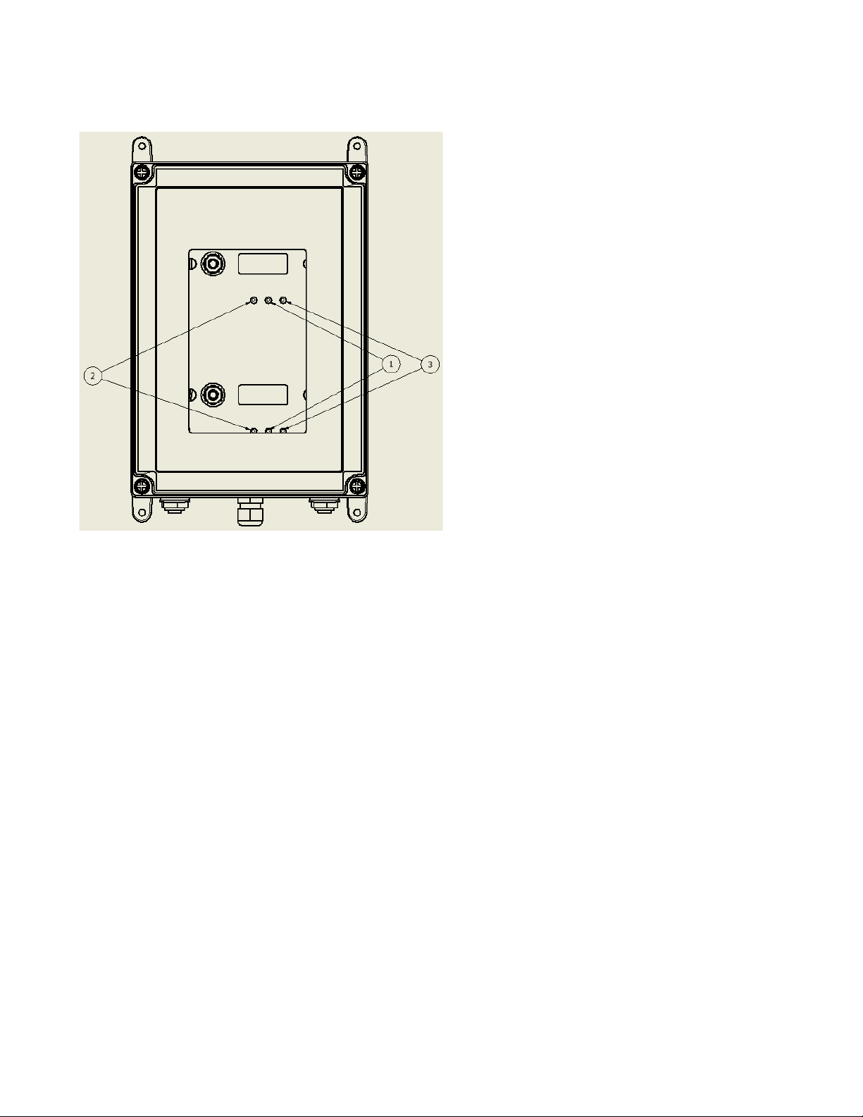
2.3 Component identification ....................................................4
2.3.1. Front View Exterior with Relays .................................5
2.3.2. Monitor Interior ...........................................................6
2.3.3. Alarm Relay Board ......................................................6
2.4 Sample Inlet Filter………………………………………...7
3: Oxygen Monitor Specifications.....................................................................................9
3.1. Performance Specifications..................................................9
3.2. Gas Detection System..........................................................9
3.3. Signal Outputs .....................................................................9
3.4.Oxygen Monitor System Default Factory Settings ............10
3.5. Wiring ................................................................................11
3.6. Initial Startup .....................................................................12
3.7. Normal Operation............................................................13
3.7.1. Signal Outputs ........................................................13
3.7.2. Instrument Faults ....................................................13
3.7.3. Routine Maintenance Schedule ...........................14
3.7.3.1. Recommended Maintenance Schedule ......................14
3.7.4. Loss of Power Indicator ..........................................14
3.7.5. Alarm Reset ............................................................14
3.8. PureAire Oxygen Monitor Programming.....................15
3.8.1. Joystick Operation ..................................................15
3.8.2. Program Flowchart .................................................16
3.8.3. Entering the Password .........................................20
3.8.3.1. Changing User Password...............................21
3.8.3.2. Enable User Password....................................23
3.8.3.3. Rest User Password .......................................23
3.9. Entering the Menus.........................................................24
3.9.1. Set 4-20mA Loop ...................................................24
3.9.2. Set Formats .............................................................26
3.9.3. Set Alarm Threshold Polarity .................................28
3.9.4. Set Latching ............................................................30
3.9.5. Resetting a Latching Alarm ....................................33
3.9.6. Set Alarm Delay .....................................................33
3.9.7. Set Zero Suppression ..............................................34
3.9.8. Set Alarm Thresholds .............................................34
3.9.9. Set Alarm Hysteresis ..............................................36
3.9.10. Set Sensor Adjust..................................................37
3.9.11. Main Operation Mode...........................................38
3.10. Maintenance & Cell Verification .................................39

PureAire Monitoring Systems
3.10.1. Sensor Verification..............................................39
3.10.1.1. Sensor Verification Gas ...............................39
3.10.1.2. Sensor Verification Equipment....................39
3.10.2. Sensor Verification Procedure...........................40
3.10.2.1. Sensor Verification to Nitrogen ...................41
3.10.2.2. Sensor Verification to Oxygen.....................41
4: Carbon Dioxide Monitor Specifications ....................................................................43
4.1 Performance Specifications ...............................................43
4.2 Gas Detection System........................................................43
4.3 Signal Outputs ...................................................................43
4.4 System Default Factory Settings .......................................43
4.5 Initial Startup .....................................................................45
4.6 Normal Operation............................................................46
4.6.1. Signal Outputs .........................................................46
4.6.2. Instrument Faults .....................................................46
4.7. Routine Maintenance Schedule......................................46
4.7.1. Recommended Routine Maintenance Schedule .......47
4.7.2. Loss of Power Indicator ...........................................47
4.7.3. Alarm Reset..............................................................47
4.8. Carbon Dioxide Monitor Programming........................48
4.8.1. Joystick Operation....................................................48
4.8.2. Program Flowchart...................................................49
4.8.3. Entering the Password ...........................................53
4.8.3.1. Changing the User Password .........................54
4.8.3.2. Enable User Password....................................56
4.8.3.3. Reset User Password......................................56
4.9. Entering the Menus.........................................................57
4.9.1. Set 4-20mA Loop .....................................................57
4.9.2. Set Formats...............................................................58
4.9.3. Set Alarm Threshold Polarity...................................61
4.9.4. Set Latching..............................................................62
4.9.5. Resetting Latching Alarm ........................................64
4.9.6. Set Alarm Delay .......................................................64
4.9.7. Set Zero Suppression................................................65
4.9.8. Set Alarm Thresholds...............................................65
4.9.9. Set Alarm Hysteresis................................................67
4.9.10. Auto Calibrate ........................................................68
4.9.11. Main Operation Mode ............................................70
4.10. Maintenance & Cell Verification .................................71
4.10.1. Sensor Calibration CO2..............................................................
71
4.10.2. Adjusting the CO2 Sensor Manually......................72
5: Appendix.......................................................................................................................74

PureAire Monitoring Systems
1:Introduction
The Dual Oxygen/Carbon Dioxide Monitor is a self-contained gas monitoring system that is ideal for
the continuous monitoring of inert gases in storage areas, confined spaces, and other locations where low
oxygen levels and/or elevated carbon dioxide levels may pose a hazard to personnel. Unlike
electrochemical sensor cells, the zirconium oxygen sensor cell and patented NDIR carbon dioxide cell
provide stable readings even in areas where temperature and humidity levels are changing. PureAire’s
Dual O2/CO2 Monitor is suitable for either indoor or outdoor use. Factory calibrated against a NIST
traceable reference standard and UL, CUL and CE approved.
PureAire’s Dual O2/CO2 Monitor combines our Oxygen Deficiency Monitor with our Carbon
Dioxide Monitor housed in a dust and watertight NEMA 4X/IP66 enclosure. The Dual Monitor
includes two 4-20ma output signals with dedicated circuits, signal outputs for both O2 and CO2, two
relays, as well as two alarm set points for both oxygen and carbon dioxide monitors.
PureAire’s Oxygen Deficiency Monitor is built with a long-lasting zirconium oxygen sensor, which
responds to low oxygen conditions within seconds and provides accurate measurements over a wide
temperature and humidity range. The Monitor will operate continuously for 10+ years with no time-
consuming, scheduled maintenance. The Monitor does not drift or lose sensitivity due to weather or
temperature changes.
PureAire’s Carbon Dioxide Monitor is built with a non-dispersive infrared sensor (NDIR) cell, which
responds to high carbon dioxide conditions within seconds and provides accurate measurements over
a wide temperature and humidity range. The NDIR CO2 sensor cell will operate continuously for
many years and requires an absolute minimum of maintenance. There are no zero or span calibration
pots to adjust and its built-in auto-calibration can save time and money in annual maintenance.
The Dual O2/CO2 Monitor may be used as a stand-alone gas detector, linked to optional PureAire
single and multipoint controllers, or connected to a centralized control and surveillance system.
This manual covers the installation, operation, and maintenance of PureAire’s Dual O2/CO2
Monitor.
NOTE: For our continual product improvement, all specifications are subject to change without notice.
1

PureAire Monitoring Systems
2
1.1.
Key Features
The Dual O2/CO2 Monitor incorporates several user-friendly features designed to simplify
installation, operation, and maintenance.
1.1.1. Long Life Zirconium Oxide O2 Sensor
The system’s O2 sensor cell has a life of well over 10 years of continuous operation. Unlike
concentration O2 cells, PureAire’s exclusive zirconium oxide sensor cell does not need an oxygen
reference gas for proper operation. The O2 monitor can detect low oxygen levels in confined spaces
and process tools without the need for a reference gas.
1.1.2. NDIR CO2 IR Sensor
The monitor’s CO2 sensor cell is a patented Non-Dispersive Infrared (NDIR) cell designed to detect
continuous levels of CO2. The cell responds quickly and has a built-in auto-calibration feature that adjusts the
sensor to ambient every 180 hours.
1.1.3. Smart Electronics
The Dual O2/CO2 Monitor incorporates a special electronic circuit that continuously monitors sensor operation. Any
cell degradation or complete failure will immediately be detected. This smart circuitry alerts the user to sensor faults
and other electrical problems that may interrupt surveillance through the standard mA signal output signal or through
the fault relay option.
1.1.4. Calibration O2
The Oxygen Monitor incorporates a stable zirconium oxide sensor that rarely requires adjustment.
Changing barometric pressure changes or changes in temperature and humidity do not affect the
zirconium oxide oxygen cell. The earth is a wonderful source of calibrated oxygen at 20.9%,therefore
under ambient conditions, visual verification of the PureAire O2 monitor to 20.9% oxygen is easily
performed. There are no zero or span pots to adjust. The O2 monitor only requires periodic testing
with nitrogen to verify the cell's response to low oxygen levels. See Section 3.10.2.1. for the testing
procedure using nitrogen.
1.1.5. Calibration CO2
The Carbon Dioxide Monitor incorporates an NDIR CO2 sensor that provides an accurate reading
that is the difference between a reference baseline setting and the measured gas concentration. The
sensor is factory calibrated and requires no user calibration but as typical with most NDIR sensors,
long-term drift can affect the baseline setting. Under normal conditions, the sensor provides
automatic baseline adjustments, and no further action is required by the user. However, under certain
conditions, manual adjustments may be required. See Section 4.10. for further explanation and
procedures for adjusting the baseline setting.
1.2.
ElectricalRequirements
Power: 24 VDC external power. A regulated 24VDC power
supply is required. Consumption: Approximately
400mA
1.3.
Physical Characteristics
Enclosure Type: NEMA 4X/IP66 - Not intended for explosive atmospheres.
Weight: 5.0 pounds (2.27 kg)

PureAire Monitoring Systems
3
2:Installation
2.1. Site Requirements
The PureAire O2/CO2 Monitor should be mounted in an area free of vibration and electrical noise or
interference. If possible, avoid areas with high temperatures or condensing humidity.
The monitor covers an area of approximately 692 square feet when mounted on a wall and should be
placed no more than 21 feet from potential leak sources such as gas lines, gas cylinders, or any areas
where a gas leak might be expected to occur.
To ensure safety, the maximum distance between two monitors mounted to the same wall, should
not exceed 30 feet.
WARNING
The PureAire O2/CO2 monitor is not designed for installation in hazardous areas. Consult
PureAire for information on enclosures for use in hazardous environments.
2.2. Mounting
Enclosure
The PureAire monitor is designed primarily for wall mounting and should be installed at a height
convenient for operation, maintenance, and viewing of the instrument display. The following is a
drawing of the mounting dimensions.
The monitor should be installed in a location where gas leaks are likely to occur or where released
gases may accumulate. It should be mounted no closer than 12 inches above floor level. Airflow
within the monitored area, the characteristics of the gas (lighter or heavier than air), and the
position of workstations and personnel should all be considered in determining the most
suitable installation location.

PureAire Monitoring Systems
4
2.3. Component Identification
1. Digital Display — Backlit display for
showing the oxygen levels inpercent.
2. Joystick — Used for selecting and adjusting
the built-in menus. The PureAire O2 monitor is
available with optional dual-level user
selectable relays. The joystick is also used to
select alarm levels, relay settings, and reset
any latching visual and audio alarms.
3. Cable Port — This is the opening in the
monitor housing for connecting the 24 VDC
power cable and 4-20 mA output.
4. Sample Inlet —
5. Sample Exhaust —
6. Mounting Feet — There are 4 feet used to
mount the oxygen monitor to a wall or other
flat surface. Mounting Feet Can be oriented
in any direction and can also be removed for
mounting the monitor flush with a wall or
other surface
7. Monitor Cover — A removable cover
that protects the interior of themonitor.
8. Monitor Cover Fasteners — There are 4
captive screws to secure the monitor cover
in place.
9. Electronics Fasteners — These captive screws secure
the electronics to the enclosure.

PureAire Monitoring Systems
5
2.3.1. Front View Exterior with Relays
Alarm Indicators — Three LED indicators for
showing:
1. Alarm level 1 OrangeLED
2. Alarm level 2 RedLED
3. Fault Alarm Yellow LED

PureAire Monitoring Systems
6
2.3.2. Monitor Interior
2.3.3. Alarm Relay Board
1. Power Analog Terminal Block — This
terminal block is where the 24VDCpower
and 4-20 mA analog output connection is
made.
2. Oxygen Sensor Connector — This
connector is where the Oxygen sensor cell
is connected. NOTE: Never connect the
sensor to this connector while the
monitor is powered. This will damage the
sensor
3. PTC Resettable Fuse — The PCB is
protected with a PTC Fuse that is
resettable and never needs to be
replaced. If it trips, you will need to turn
the power off to the monitor. When
power resumes the fuse will reset.
1. Relay 2
2. Relay 1
3. Fault Relay
4. Remote Reset
5. Pump Connector
6. Oxygen Sensor Connector

PureAire Monitoring Systems
7
Sample air can enter from
either port. This is the
reason the water filter must
be located at the end of the
sample line.
2.4. Sample Inlet Filter
To protect the pump from water, a special filter is supplied with the monitor. On installation, attach
the water filter to the sample inlet by pushing the filter into the ¼” tube compression fitting.
Aligning the arrow, (printed on the filter) towards the monitor. The filter pulls air from both vertical
and horizontal tubes. Never connect any sampling tubing to either tubing ports. When sampling
remote, ALWAYS locate this filter at the end of the sample line.
The PureAire O2 /CO2 Monitor has an internal sample pump flow rate that is programmed at the
factory and cannot be changed in the field. A flow sensor on the relay board continually monitors
flow rate. When a loss of flow is detected, a signal is sent to the fault relay and the front mounted
LED will activate. Sample flow to the monitor is continuously monitored and controlled by the flow
control microprocessor.
NOTE: If using longer lengths of sample tubing, the water filter must be located at the end
of the sample line to work properly.
NOTE: If the sample line is blocked, the fault indicator will illuminate, and the pump will
accelerate to try and reestablish the proper flow rate. If the line is cleared, the
pump will speed and slow down and the fault light will turn off when the flow rate
is back to factory setting.
Depending on the environment, replacement of this filter should be performed every 12 months. In
dusty environments, a standard filter (p/n 23102) should be added at the monitor. If the filter
becomes completely blocked, the internal flow sensor will detect the loss of flow and activate the
fault relay and LED. Order water filter part number 90179

PureAire Monitoring Systems
8
”
of
.
**NOTE: PureAire recommends
the use of polypropylene sample
tubing with the dimensions of 1/4
OD by 3/16” ID. The total length
tubing should not exceed 100 feet
NOTE: When used in wash
down areas, the water filter
drain must be oriented opposite
the water flow.
(i.e., orient the drain towards
the back of the monitor to
prevent water from building up
inside the drain.)
Photo shown is a
waterproof monitor
located at the risk
site.
If any length of
sample tube is
needed to sample
remote, the water
filter must be located
at the
end of the
sample tubing.
¼” tube push to
connect fitting **
Water Sample filter p/n
90179
Sample air can enter from
either port. This is the
reason the water filter must
be located at the end of the
sample line.

PureAire Monitoring Systems
9
3:Oxygen Monitor Specifications
NOTE: For our continual product improvement, all specifications are subject to change without notice.
3.1. PerformanceSpecifications
Sensor Type: Long Life Zirconium Oxide Sensor Cell 0-25%
Response Time: Within 1 second of any change in O2.
Accuracy: ± 1% of full scale
Fault Indicators: Loss of VDC power (analog signal drops to 0 mA).
Sensor cell failure: Fault relay activated.
Operating Temp: -40° to 134°F (-40° to +55°C); consult PureAire for lower or higher operating
temperatures.
Humidity: 0 to 95% RH; consult PureAire for sensors that can operate in100%
condensing RH environments.
Environment: PSU only UL spec, Altitude 2000 m, Pollution Degree 3, Intended for Indoor Use.
UL / CUL listing: Measuring Equipment E363306
Ce EN 61000-3-2:2006 EMC, EN 61000-3-3:2008 EMC, EN61010-1-3-2013 LVD
3.2. . Gas Detection System
Type: Long Life Zirconium Oxide Sensor Cell, Range0-25%
Sensor Life: 8 to 10+ years under normal conditions.
Transmitter: Microprocessor electronics with built-in 3-digit backlit LCD display
Joystick-operated menus
3.3. . Signal Outputs
Standard Analog Output: DC 4-20 mA
Relay Output: Dual level user selectable alarm relays and one fault relay
Rated, 2amps @ 24VAC or 24VDC

PureAire Monitoring Systems
10
3.4. Oxygen Monitor Default Factory Settings
The PureAire O2 Deficiency Monitor is shipped with factory defaults for the alarm relay
settings. The following are the factory defaults:
Menu Function
Factory Default
Menu Defined
Set 4-20mA loop
The mA output is set at
the factory using a
calibrated Fluke meter.
Use this function to adjust the
Oxygen monitors 4mA, (Zero) and
20mA, (Span) to your PLC or
distributive control system.
Set Formats
LED and alarm relay
State **
Alarm 1 = Normal
Alarm 2 = Normal
Fault = Normal
Do you want the relays to
energize, (normal) or de-energize,
(fail safe) when the alarm
activates?
Set Alarm Threshold
Polarity
Alarm 1 = Inverted
Alarm 2 = Inverted
Audio = Inverted*
Do you want to alarm at a level
higher, (normal) or lower,
(inverted) than the alarm
threshold?
Set Latching
Alarm 1 = Non-latching
Alarm 2 = Non-
latching
Audio = Non-latching
Do you want the alarm to
automatically reset? (non-latching)
or do you want to manually reset
the alarm? (latching)
Alarm Delay
Alarm = 5 seconds
How long do you want to wait
until the alarms activate?
Zero Suppression
000 = 0.00%
Refer to section 3.9.7.
This function is Not Enabled on
the Oxygen monitor.
Set Alarm
Thresholds
Alarm 1 = 19.5 %
Alarm 2 = 18.0 %
Audio = 19.5%*
At what level do you want to
alarm?
Set Alarm Hysteresis
Alarm 1 = 0.0 %
Alarm 2 = 0.0 %
Audio = 0.0 %
For use when using the O2 monitor
for control of valves and
processes. See Section 3.9.9.
Sensor Adjustment
No factory default
For use when dynamically gas
calibrating the Oxygen monitor to
a known span gas.
See Section 3.9.10.
Manage Passwords
Factory default is 557
For use when changing the
password from factory default to a
new password of your choice.
NOTE: The built-in relay settings may be changed by the user in the field. Refer to
Section 3.9.2.
* NOTE: The Audio alarm feature is optional.
** NOTE: The LED indicators on the front panel are connected directly to the alarm
relays.

PureAire Monitoring Systems
11
3.5. Wiring
PureAire monitors require a 3-wire shielded cable for analog output and 24 VDC
power input. A three-wire shielded cable; 3-conductor, 18 AWG-stranded General
Cable E2203S.30.860, or equivalent is recommended for the connection. The analog
out and VDC power in connections are made on the terminal block inside the monitor
housing.
These connections are made as follows:
PureAire provides
the plug-in power
supply
Caution
DO NOT connect to an active/powered current-loop receiver. The PureAire
Oxygen monitor supplies the current loop power.
Pin # Connection Description
-
Common (Signal Ground) 0V
-
Common (Signal Ground) 0V
MA
Signal Out DC 4-20mA Output
+
Power DC + 24V Input
+
Power DC + 24V Input
NOTE: PureAire has added additional contacts for +24VDC power and Common to
accommodate additional wiring for remote horns and strobes

PureAire Monitoring Systems
12
3.6. Initial Startup
Once the installation of the gas detector has been completed, it is ready for startup. The
following procedures should be performed before putting the instrument into operation:
Check the integrity of all wiring.
Apply 24 VDC power.
The instrument should now be powered up. Upon power up, the PureAire O2 Monitor LCD displays
the PureAire logo and then starts a 4-minute, (240 seconds) count down as the current to the
zirconium oxide O2 sensor stabilizes. The monitor will output a 4 mA signal during the entire warm-
up period. After the countdown, the oxygen sensor will continue to reach its operating temperature
for approximately 30 minutes and the reading displayed will slowly increase to ambient. Do not
make any adjustments to the reading until after the monitor has been powered for at least an
hour.
NOTE: When the PureAire O2 monitor is supplied with an Audio Horn, it will activate
momentarily at the completion of the warmup.
NOTE: The PureAire O2 monitor’s reading may be adjusted to the ambient oxygen level.
See section 3.10.1. for instructions on adjusting.
Oxygen
239 WARM

PureAire Monitoring Systems
13
3.7. Normal Operation
The PureAire O2 monitor is a single-point monitor designed for the continuous detection
and measurement of ambient oxygen concentration levels.
3.7.1. Signal Outputs
The PureAire O2 monitor outputs a continuous 4-20 mA analog signal proportional to the measured
concentration of oxygen. 4 mA represents 0% O2 and 20 mA represents 25% O2 which is the full
range. In the event of a system fault, a specific factory-defined code will be displayed on the local
digital display. This code will indicate the exact nature of the system fault.
CAUTION
DO NOT connect to a powered current loop receiver. The PureAire Oxygen
monitor supplies the current loop power.
3.7.2. Instrument Faults
The PureAire O2 monitor incorporates several self-checking features to ensure reliable
operation. In the event that a fault condition is detected, the analog output signal is altered:
Examples of some common error codes are displayed in the following table:
Condition Analog Signal
**Supply Voltage Out of
Range Fault code 16 Analog output drops to 2 mA
Transmitter cable cut Analog output drops to 0 mA
O2 Cell complete failure
Fault Code 128
Analog output drops to 2 mA
Fault Relay activates
(Available with Relay Option Only)
O2 System Warm Up
Analog output drops to 2 mA
Fault Relay activates and turns off when the
system is in the Oxygen operation mode
(Available with Relay Option Only)
O2 Cell voltage fault
Fault Code 64
Analog output drops to 2 mA
Fault Relay activates
(Available with Relay Option Only)
EEPROM Fault 08 Analog output drops to 2mA
NOTE: All system faults are displayed on the front panel. Each fault has its own specific code to identify
the specific problem. Please contact PureAire whenever a fault is displayed.
** When using your own power supply, please ensure that the voltage is regulated to
24VDC +/- 0.5 volts. If the voltage is too low or high, you will activate a “Supply Voltage
Out of Range fault and disable the monitor.**
NOTE: If a Fault condition clears itself, (Yellow LED is no longer illuminated)
The Fault message will continue to scroll until manually cleared.
To clear the fault message, push the joystick down (- Minus)

PureAire Monitoring Systems
14
3.7.3. Routine Maintenance Schedule
Continuous gas detection systems depended upon to measure and detect hazardous gas leaks in the
workplace require periodic maintenance to ensure proper operation. The frequency with which this
routine maintenance is required depends on the environment. The following table is intended to serve
as a general guideline for routine maintenance. The conditions in your particular application, as well as
your organization’s maintenance policies, will ultimately determine the best routine maintenance
schedule for your equipment. Routine Visual Checks
Items to check Check for power and proper operation
Condition/status
when operating
properly
The unit should be outputting a 17.4 mA signal
when the oxygen level is at 20.9%. The LCD
digital display should also indicate 20.9% 02
when the oxygen is at ambient levels.
3.7.3.1. Recommended Routine Maintenance Schedule
Routine Visual Checks Every 6 - 12 months
Sensor Verification with nitrogen Every 6 -12months**
** The ambient oxygen level is 20.9%; therefore, under ambient conditions, visual verification of the
PureAire O2 monitor to 20.9% oxygen is easily performed. The O2 monitor only requires periodic
testing with nitrogen to verify the cell's response to low oxygen levels. See Section 3.9.10 for how to
make minor adjustments.
3.7.4. Loss of Power Indicator
In the event the PureAire O2 monitor loses 24VDC power, the 4-20 mA analog output signal drops to
0mA. The LCD display will also display a blank screen.
3.7.5. Alarm Reset
The PureAire O2 DRA monitor is supplied with the alarm relays, whenever the monitor's alarms are
activated, the built-in alarm relays, panel-mounted LEDs and the audio horn will also activate. When
the relay settings are non-latching, the alarm relays, LEDs, and the horn will automatically reset. If
the relay settings are latching, then a manual reset of the alarms is required. Resetting the alarms can
be performed through the use of the joystick or using the remote reset function.
Joystick – You must enter the password to enter the reset function. After the password is entered and
accepted, push the joystick in; (enter) to reset the alarms.
Remote Reset – See section 2.2.3The alarm relay board has a two-pin connector for wiring to a
remote switch. When connected to a switch, this remote reset will bypass the joystick and a password
will not be needed to reset the alarms.
NOTE: The oxygen levels must recover above the alarm thresholds before the horn can be
reset from the remote reset switch or joystick.

PureAire Monitoring Systems
15
3.8. PureAire O2Monitor Programming
The PureAire O2 Deficiency Monitor is supplied with user-selectable settings to adjust the alarm
settings, 4 and 20mA output, and minor sensor adjustments.
The settings are arranged in menus that are accessed by moving the joystick. To access the menus a
factory set password is used.
NOTE: The digital display is calibrated for oxygen. The range is stated on the model label and can
also be accessed via the joystick on the front panel. In the measurement mode, pushing the joystick
down will scroll the gas and range on the display. Pushing the joystick down again will stop the
scrolling and display the gas again.
NOTE: The PureAire O2 Deficiency Monitor will continuously monitor oxygen while accessing the
menus. The alarm, fault relays, and mA output are all active and on line while making any
changes to the menus.
3.8.1. Joystick Operation
The PureAire O2 monitor uses a 4-position joystick with a center pushbutton for selecting
menus and changing values. The joystick is programmed to the standard protocol as
follows:
NOTE: The joystick has a built-in delay to prevent accidental tampering with the
menus. deliberate entries are required.
CAUTION: Only qualified personnel should perform programming, maintenance, and
sensor verification
+ Plus
Previous Next
- Minus
Plus – Pushing the joystick in this direction increases the value
Minus – Pushing the joystick in this direction decreases the value
Next – Pushing the joystick in this direction moves you to the next level of the menu hierarchy.
Previous – Pushing the joystick in this direction takes you out to the last level of menu hierarchy.
Enter – Pushing the joystick directly in the center enters the information into the microprocessor
Table of contents
Other PureAire Measuring Instrument manuals

PureAire
PureAire ST-46 LEL User manual

PureAire
PureAire KF-25 User manual

PureAire
PureAire Air Check O2 User manual

PureAire
PureAire Air Check EX User manual

PureAire
PureAire Air Check O2 User manual

PureAire
PureAire Air Check O2 99066 User manual

PureAire
PureAire 99062 User manual

PureAire
PureAire Air Check O2 KF-25 User manual

PureAire
PureAire Air Check EX ST-46 User manual

PureAire
PureAire 99040 User manual