manuals.online logo
Brands
  1. Home
  2. •
  3. Brands
  4. •
  5. Purelogic
  6. •
  7. Accessories
  8. •
  9. Purelogic PLL-R2 User manual

Purelogic PLL-R2 User manual

This manual suits for next models

2

Popular Accessories manuals by other brands

Quincy lab 140AE-1 operating manual

Quincy lab

Quincy lab 140AE-1 operating manual

HomePro ZIR000 user manual

HomePro

HomePro ZIR000 user manual

DOL 20SCR Technical user guide

DOL

DOL 20SCR Technical user guide

RAB Smart Task installation manual

RAB

RAB Smart Task installation manual

Kemppi KMS 300 quick guide

Kemppi

Kemppi KMS 300 quick guide

Stearns 57,500 Series Installation and service instructions

Stearns

Stearns 57,500 Series Installation and service instructions

iGuzzini TWILIGHT COPENAGHEN manual

iGuzzini

iGuzzini TWILIGHT COPENAGHEN manual

Adelaide Annexe & Canvas Avan Deluxe installation guide

Adelaide Annexe & Canvas

Adelaide Annexe & Canvas Avan Deluxe installation guide

OHAUS 5000 instruction manual

OHAUS

OHAUS 5000 instruction manual

HOME8 WLS1300 quick start guide

HOME8

HOME8 WLS1300 quick start guide

MAXBOTIX MaxSonar quick start guide

MAXBOTIX

MAXBOTIX MaxSonar quick start guide

ioSmart iSmart56 Installation and user guide

ioSmart

ioSmart iSmart56 Installation and user guide

Focusrite Scarlett 18i8 user guide

Focusrite

Focusrite Scarlett 18i8 user guide

Velleman ED38105 user manual

Velleman

Velleman ED38105 user manual

JumpSport SkyBounce user manual

JumpSport

JumpSport SkyBounce user manual

Prima-Temp PRIYA Instructions for use

Prima-Temp

Prima-Temp PRIYA Instructions for use

Tefcold BC85I-BC85I W user manual

Tefcold

Tefcold BC85I-BC85I W user manual

Vaisala WMS302 user guide

Vaisala

Vaisala WMS302 user guide

manuals.online logo
manuals.online logoBrands
  • About & Mission
  • Contact us
  • Privacy Policy
  • Terms and Conditions

Copyright 2025 Manuals.Online. All Rights Reserved.

INSTRUCTION
MANUAL
Ohmic workpiece search
sensor PLL-R2
8 [800] 555-63-74 www.purelogic.ru
01. General information
The PLL-R2 set is designed for metal workpiece surface search in C C plasma cutting
devices.
The set consists of two devices: power supply unit PLL-R2P and measuring unit PLL-R2S.
The measuring unit is to be installed next to the torch on the Z axis, and the PLLR2P power
supply unit is to be installed onto the control panel of the C C system. The units are
connected via cable (Fig. 7).
The sensor allows to adjust the sensitivity. PLL-R2 is equipped with trigger indicators, as
well as an opto-isolated interface for connecting to a C C machine controller.
The sensor provides with measurements when cutting parts are located under water (the
response threshold is selected individually by the sensor response sensitivity adjusting).
The measuring unit PLL-R2S has the international protection class IP50 (protection
against dust penetration in quantities, that do not affect the performance of the product).
02. Delivery set
•PLL-R2P device – 1 pc.
•PLL-R2S device – 1 pc.
•Connecting cable – 1 pc.
•Instruction manual – 1 pc.
•Mating connectors – 6 pcs.
•Sensor with cable – 1 pc.
03. Technical data
PLL-R2 supply voltage 230 VAC
PLL-R2 input power 6 W
Measured resistance, approximately <1 Mohm
Measured voltage 40 V
Insulation resistance 500 М ohm
Working temperature 0...60 °С
Overall dimensions of PLL-R2P (W x H x D) 161 x 60 x 70 mm
Overall dimensions of PLL-R2S (W x H x D) 138 х 66 х 95 mm
Protection class IP50
Weight with packaging 1.5 kg
ALL CO ECTIO S SHALL O LY BE PROVIDED I DEE ERGISED STATE!
Fig. 1. PLL-R2P device dimensions
Fig. 2. PLL-R2S device dimensions
04. Controls, indication and connection
Indication Input/ Output
A: Sensor 2 F: Sensor 2 (output)
B: Sensor 1 H: Sensor 1 (output)
C: Enable J: Enable
D: Power E, G, I: common
Fig. 3. Front view of the PLL-R2P device
Fig. 4. Rear view of the PLL-R2P device
Fig. 5. Front view of the PLL-R2S device
Fig. 6. Rear view of the PLL-R2S device
Fig. 7. Interconnecting cable diagram
Fig. 8. Interconnecting cable diagram
Fig. 9. Sensor connection to a C C plasma system
05. Description of sensor operation
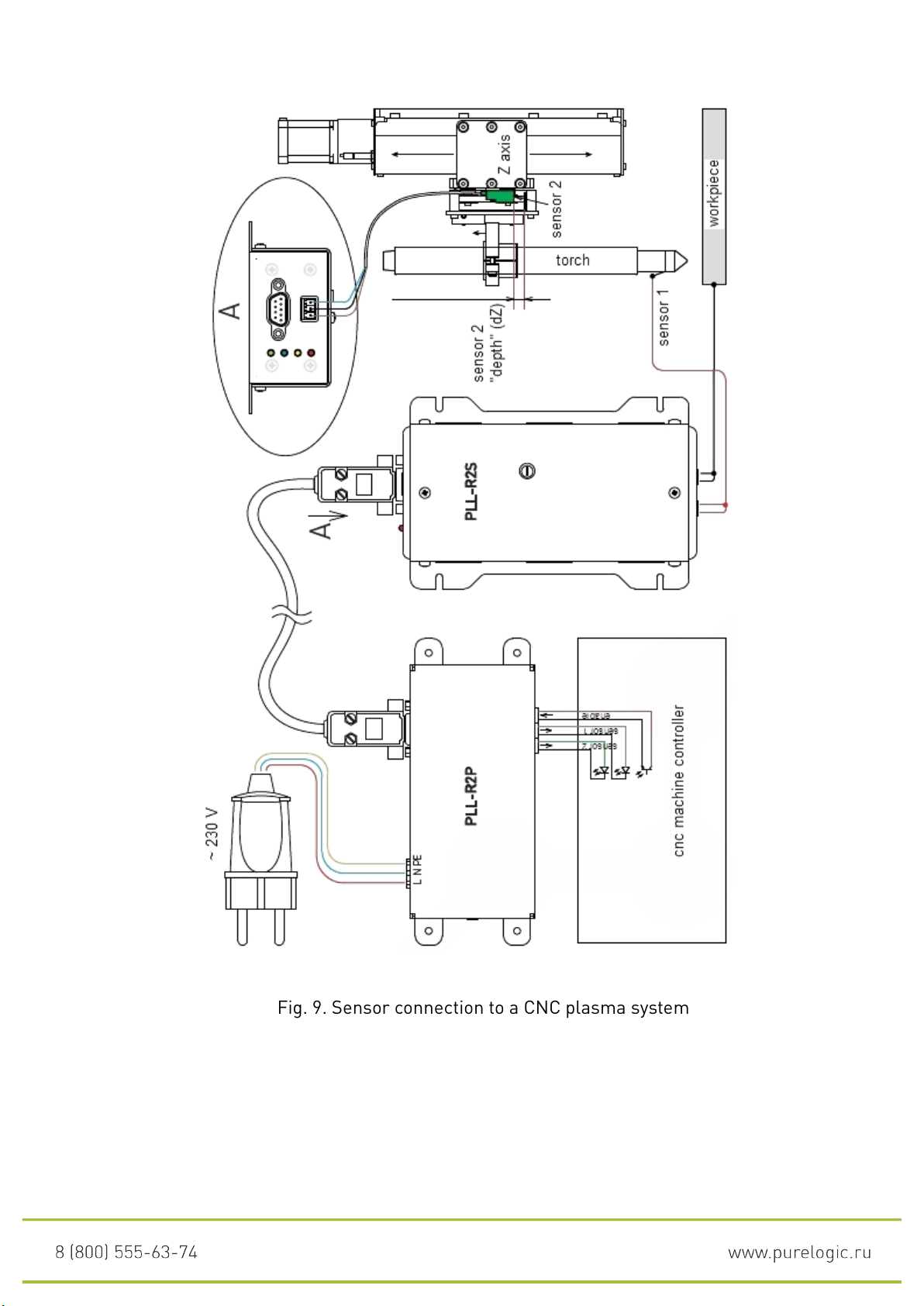
An ohmic sensor allows to detect the workpiece surface when the torch moves down.
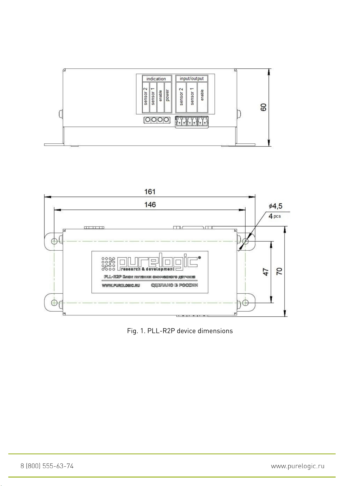
When the torch cap touches the workpiece, the “Sensor 1” signal appears. If for any reason
the first sensor does not work and the Z axis continues moving down, then dZ mm (Fig. 9)
will trigger sensor 2 and two signals will immediately appear at the output: “Sensor 1” and
“Sensor 2”. In this case, to obtain the torch height above the workpiece surface, it is
necessary to correct the Z coordinates by the distance dZ.
The sensitivity control is designed to reduce the sensor sensitivity in the case of strong
interference, which can cause false activation, or to increase the sensitivity in the case of
contaminated workpiece.
06. Warranty
Warranty service life is 12 months from the purchase date.
The warranty is only preserved if operation and scheduled maintenance conditions are
observed.
1. General provisions
1.1. If the goods is purchased as component parts, Seller shall guarantee operability of
each component part individually, but is not responsible for the quality of their joint
operation (incorrect selection of component parts. In case of any questions you can consult
the company’s specialists).
1.2. Seller does not provide any warranty for compatibility of the purchased goods and the
goods possessed by Buyer, or purchased by them from any third parties.
1.3. Specifications and configuration of the product can be changed by manufacturer
without prior notice due to continuous technical improvement of the products.
2. Conditions for access to warranty service
2.1. The goods is accepted for warranty service in the same configuration in which it was
purchased.
3. Warranty service procedure
3.1. The warranty service is carried out by testing (checking for) the declared malfunction
of the product.
3.2. The warranty service is carried out if the malfunction is confirmed.
4.The warranty does not cover glass, electric lamps, starters and consumable materials,
and:
4.1. any goods damaged due to improper transportation and storage conditions, incorrect
connection, offdesign operation, or in conditions not stipulated by the manufacturer
(including temperature and humidity beyond recommended range), damaged due to effect
of exterior circumstances (power supply voltage surges, natural disasters, etc.), and
mechanically or thermally
damaged goods.
4.2. Goods with traces of effect and (or) ingress of foreign objects, substances (including
dust), liquids, insects and those with extraneous texts.
4.3. Goods with traces of unauthorized tampering and (or) repair (tampering signs,
primitive soldering, traces of component replacement, etc.).
4.4. The goods having self-diagnostic means indicating improper operation conditions.
4.5. Highly technical Goods in respect of which installation and assembly works were
carried out neither by Seller’s specialists, nor by organizations recommended by Seller,
except cases directly stipulated in the goods documentation.
4.6. The Goods operated in conditions where power supply did not comply with
manufacturer’s requirements, and if the electrical network and equipment protection
devices are unavailable.
4.7. The Goods which was re-sold by the initial buyer to third-party persons.
4.8. The Goods damaged due to use of low-quality or outdated spare parts, consumable
materials,
accessories and if spare parts, consumable materials and accessories not recommended
by the manufacturer were used.
This product was manufactured and accepted in accordance with mandatory requirements
of the applicable technical documentation and deemed ready for operations.
Batch o: QCD:
We draw your attention to the fact that changes are possible in the operation manual due
to constant technical improvement of products. You can always download the latest
versions on our website www.purelogic.ru