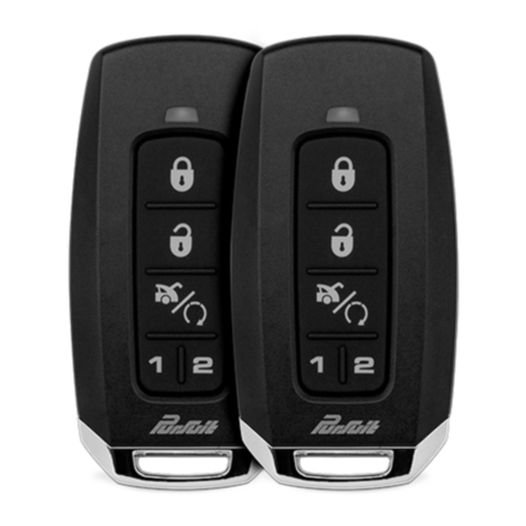
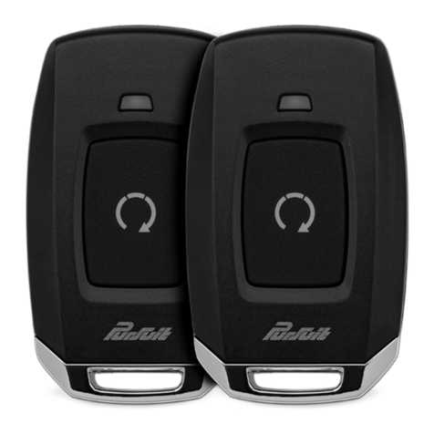
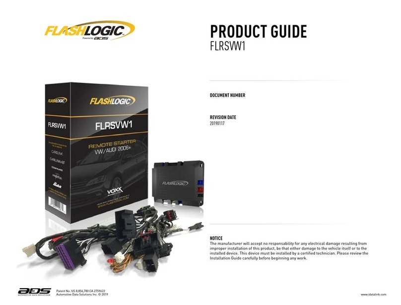
PURSUIT PRO9233Z Installation and operating manual

Installaon and Reference Guide
2020 Voxx Electronics Corporaon. All rights reserved. PRO9233Z_RevA_08/20
2 Wire Harness Colors and Funcons
2 Input / Output Connector
4 Control Connector
5 Door Lock Connector
6 External Components
6 Shock Sensor
6 Valet / LED
6 Data Bus Interface (DBI)
6 Telemacs
7 Setup Opons
7 Security Control
PRO9233Z
Security Upgrade
11 System Programming
11 Programming Mode Entry / Exit
12 Feature Bank Opons
12 Data Port Protocol Selecon
12 Dome Light Delay
13 Silent Arm and Disarm
13 User Selectable LED
13 System Diagnoscs
13 Troubleshoong Trigger Zones
13 Adjusng Shock Sensor
14 Alarm Override Procedures
15 Wiring Diagrams
15 Door Lock Connecons
18 Starter Kill Relay
19 Full System Connecons
Thank you for trusng Pursuit products! If you are a consumer, please note:
Professional installaon is strongly recommended.
This manual assumes the installer has adequate knowledge of the following experse. Therefore, it does not
cover these topics in detail:
• 12-volt electronics
• Tesng and verifying circuits
• Making safe and lasng wiring connecons
• Factory ignion, power, lighng, data bus and sensing systems
• Factory systems and components to avoid
• Safe wire roung, circuit protecon and product placement
• Access to vehicle-specic technical informaon
In addion, this manual assumes the installer has the proper tools, skill and facilies to perform a professional installaon.
Performing an improper installaon could result in damage to the vehicle or its components, improper system funcon,
unsafe vehicle operaon or physical injury. Such instances would not be covered by the vehicle manufacturer's warranty,
nor by Voxx Electronics, Inc.
Detailed Descripons Quick Reference

PRO9233Z_RevA_08/20
2
Detailed Descripons: Wire Harness Colors and Funcons
Input / Output Connector (14-pin connector) See page 19 for the full system diagram.
These wires are listed in order of their placement in the harness connector.
1 2 3 4 5 6 7 8 9 10 11 13 1412
7. GREEN/WHITE – Dome Light Output (-)
The GREEN/WHITE wire supplies Ground (-) when Unlock is acvated from the Remote Control. This output will
automacally turn o aer 30 seconds.
1. WHITE/RED – Parking Light Relay Input (Internal Relay Pin 87)
The WHITE/RED connects to vehicle 12-Volt (+) or Ground (-) to supply the relay output (WHITE wire).
Vericaon for default seng:
• If the vehicle parking light wire registers 12-Volt (+) when the parking lights are on, connect the WHITE/RED wire to a
constant 12-Volt (+) vehicle wire.
• If the vehicle parking light wire registers Ground (-) when the parking lights are on, connect the WHITE/RED wire to a
reliable vehicle ground source.
2. WHITE – Parking Light Relay Output (Internal Relay Pin 30)
At its default seng, the WHITE wire supplies 12-Volt (+) or Ground (-) to the vehicle's parking light wire based on the
connecon of the relay input (WHITE/RED wire).
Vericaon: The vehicle parking light wire registers 12-Volt (+) or Ground (-) when the parking lights are turned on.
6. YELLOW – Ignion Input (+)
The YELLOW wire connects to the vehicle's primary ignion wire. This wire will be used for system programming and
override.
Vericaon: This ignion wire registers 12-Volt (+) when the key is in the accessory, ignion, and start posions.
Note: Before making this connecon, remove all module fuses unl the system is completely connected.
4. WHITE/BLACK – Siren Output (+)
The WHITE/BLACK wire supplies 12-Volt (+) to power the siren. Aer mounng the siren, connect the BLACK wire to a
reliable ground source, and connect the WHITE/BLACK wire to the siren’s RED wire.
3. RED – 12-Volt Input (+)
The RED wire connects to the vehicle’s primary 12-Volt (+) wire to power the system.
Vericaon: The power wire registers 12-Volt (+) at all mes.
Note: Before making this connecon, remove all module fuses unl the system is completely connected.
5. PURPLE – Door Trigger Input (+)
The PURPLE wire connects to the vehicle's door trigger wire. This wire will detect a 12-Volt (+) input.
Vericaon: The vehicle door trigger wire registers 12-Volt (+) when a door is opened and opposite when closed.
Note: If the door trigger registers as Ground (-) when a door is opened, use the BROWN, Pin 8, input.

PRO9233Z_RevA_08/20 3
Detailed Descripons: Wire Harness Colors and Funcons
Input / Output Connector (14-pin connector) (Cont.) See page 19 for the full system diagram.
These wires are listed in order of their placement in the harness connector.
14. GREEN/LIGHT BLUE – Ch. 4 Aux. Output (-)
The GREEN/LIGHT BLUE wire supplies Ground (-) when acvated from the remote control.
12. LIGHT GREEN – Trunk Trigger Input (-)
The LIGHT GREEN wire connects a trunk switch that, when triggered, supplies a Ground (-) output. If the system is
armed, this input will trigger the alarm.
13. GRAY/BLACK – Hood Trigger Input (-)
The GRAY/BLACK wire connects a hood switch that, when triggered, supplies a Ground (-) output. If the system is armed,
this input will trigger the alarm.
8. BLACK/WHITE – Horn Output (-)
The BLACK/WHITE wire connects to the vehicle's horn wire and supplies Ground (-) when acvated from the system.
Vericaon: The vehicle horn wire registers Ground (-) when the horn is acvated.
9. BLACK – Ground Input (-)
The BLACK wire connects to a reliable vehicle ground (-) source to power the system.
Vericaon: The vehicle ground (-) source wire registers ground (-) at all mes.
Note: Before making this connecon, remove all module fuses unl the system is completely connected.
10. ORANGE – Starter Kill Output (-)
The ORANGE wire supplies Ground (-) when the alarm is armed and when the remote start is ON.
11. BROWN – Door Trigger Input (-)
The BROWN wire connects to the vehicle's door trigger wire. This wire will detect Ground (-) input.
Vericaon: The vehicle door trigger wire registers Ground (-) when a door is opened and opposite when closed.
Note: If the door registers as 12-Volt (+) when the door is opened, use the PURPLE (Pin 5) input.

PRO9233Z_RevA_08/20
4
5. BLUE – Trunk Shunt Input (-/+)
The BLUE wire connects to the vehicle 's trunk release motor wire. This wire will disable the alarm's DARK GREEN trunk
trigger input and shock sensor when a pulse is detected.
Vericaon: The vehicle's trunk release motor wire will test Posive or Ground (-) when the trunk release funcon is
preformed on the vehicle's factory Keyless entry remote.
Note: This input is programmable. Refer to Bank 2, Feature 18 on page 7.
Detailed Descripons: Wire Harness Colors and Funcons
Control Connector (5-pin connector) (Cont.) See page 19 for the full system diagram.
These wires are listed in order of their placement in the harness connector.
4. RED/BLACK – Disarm 2 Input (-/+)
The RED/BLACK wire connects to the vehicle's unlock trim switch wire. This wire will prevent the alarm from disarming
when the unlock funcon is preformed from the vehicle's door lock trim switch.
Vericaon: The vehicle's door unlock trim switch wire will test Posive (+) or Ground (-) when the unlock funcon is
pressed on the door lock trim switch.
Note: This input is programmable. Refer to Bank 2, Feature 17 on page 7.
3. GREEN/YELLOW – Arm 1 Input (-/+)
The GREEN/YELLOW wire connects to the vehicle's Posive (+) Lock Motor wire. This wire will ARM the alarm when a
Posive (+) pulse is detected.
Vericaon: The vehicle's door lock motor wire will test Posive (+) when the Lock funcon is pressed on the factory
keyless entry remote or from the door lock trim switch.
Note: This input is programmable. Refer to Bank 2, Feature 14 on page 7.
1. GREEN/BLACK – Arm 2 Input (-/+)
The GREEN/BLACK wire connects to the vehicle's door lock trim switch wire. This wire will prevent the alarm from arming
when the Lock funcon is preformed from the vehicle's door lock trim switch.
Vericaon: The vehicle's door lock trim switch wire will test Posive (+) or Ground (-) when the Lock funcon is pressed
on the door lock trim switch.
Note: This input is programmable. Refer to Bank 2, Feature 16 on page 7.
2. RED/YELLOW – Disarm 1 Input (-/+)
The RED/YELLOW wire connects to the vehicle's Posive (+) Unlock Motor wire. This wire will disarm the alarm when a
Posive (+) pulse is detected.
Vericaon: The vehicle's door unlock motor wire will test Posive (+) when the unlock funcon is pressed on the factory
keyless entry remote.
Note: This input is programmable. Refer to Bank 2, Feature 15 on page 7.
1 2 3 4 5

PRO9233Z_RevA_08/20 5
Door Lock Connector (2-pin connector) See page 19 for the full system diagram.
These wires are listed in order of their placement in the harness connector.
1. RED – Door Lock (-)
The RED wire supplies Ground (-) when the Lock funcon is acvated from the remote control or system.
Vericaon: The vehicle lock wire registers 12-Volts (+) or Ground (-) when the Lock buon is acvated.
Note: Addional parts may be required. See Page 11 for common door lock wire diagrams.
2. GREEN – Door Unlock (-)
The GREEN wire supplies Ground (-) when the Unlock funcon is acvated from the remote control or system.
Vericaon: The vehicle lock wire registers 12-Volt (+) or Ground (-) when the Unlock buon is acvated.
Note: Addional parts may be required. See Page 15 for common door lock wire diagrams.
1 2
Detailed Descripons: Wire Harness Colors and Funcons

PRO9233Z_RevA_08/20
6
Detailed Descripons: External Components
Shock Sensor
The shock sensor plugs into a 4-pin connector on the Pursuit module. It should be securely aached to a vehicle surface
or sturdy wire harness. Tesng takes place aer all connecons are made and the system is powered up. Refer to Quick
Reference: System Diagnoscs on page 13 for instrucons on tesng and adjusng the shock sensor.
LED / Valet Programming Port
The LED / Valet Programming port is used to for feature programming and Valet Override.
1. Find a suitable locaon to mount the supplied LED / Valet Programming buon. Locate a clear spot on the vehicle’s
dashboard that will be seen from the outside of the vehicle.
2. Drill a 5/16 inch hole and mount the LED / Valet buon. Route the wires to module and plug into proper locaon.
Telemacs Interface / Weblink Programming Port
The 4-pin Telemacs port enables a connected interface such as CarLink to expand system control to a smartphone or
tablet. The following features may be able to be acvated from a connected device:
• Door Lock Control
• Remote Start
• Trunk Release
• Auxiliary Output
• Sliding Doors
Weblink Programming
This port can also be used to connect your FlashLogic Weblink for feature programming and soware updang. Once
connected please visit www.ashlogic.com.
Data Bus Interface (DBI) Port
The 4-pin Data Bus Interface enables a FlashLogic door lock or transponder interface to connect to and communicate
with the vehicle data bus. The combined system saves installaon me as many features that normally require individual
connecon can be accessed and controlled through the data bus. Please refer to the D2D (Data to Data) funcon list
available per vehicle at www.FlashLogic.com.

PRO9233Z_RevA_08/20 7
Detailed Descripons: Setup Opons
Security Control (Bank 2) See page 11 for Programming Instrucon.
1 Chirp 2 Chirp
3 Chirp 4 Chirp 5 Chirp 6 Chirp
1 Lock / Unlock Func�on 500ms 3.5sec
500ms L, DBL UL DBL L, 500ms UL DBL L, DBL UL 500ms L, 350ms UL
2 Igni�on Lock OFF ON
3 Igni�on Unlock OFF ON
4 Auto Relock OFF Auto Lock Only
Auto Lock & Arm
5 Auto Arming / Locking OFF Auto Arm Only
Auto Lock & Arm
6 Door Trigger Instant Delay
7 1 or 2 Wire Disarm 2 Wire 1 Wire
8 No�fica�on Sound Both Siren Only
Horn Only
9 Horn Timing 16ms 30ms
40ms 50ms 10ms
10 Valet Override Method Valet Custom Code
11 Security Profile All On Doors Off
Hood/trunk OffAll OffAll ON w/ OEM RS
12 Data Port Protocol ADS DBI
13 Disarm Input 120ms Dr OR Pass 80ms Dr OR Pass 120ms, UL & Light 80ms, UL & Light
14 Arm 1 Input Auto Detect Posi�ve Nega�ve
15 Disarm 2 Input Auto Detect Posi�ve Nega�ve
16 Arm 2 Input Auto Detect Posi�ve Nega�ve
17 Disarm 2 Input Auto Detect Posi�ve Nega�ve
18 Trunk Shunt Input Auto Detect Posi�ve Nega�ve
19 Dome Light Delay Timer OFF / Program 15sec 30sec
45sec 60sec 120sec
20 Alarm Trigger Length 30sec 45sec 60sec
90sec 120sec
Feature Bank 2
Op�ons
Features
Feature 1: Lock / Unlock Funcon
Funcon: Set the lock / unlock output ming and funconality for specic vehicle lock types.
Seng Choices:
• Opon 1 - Lock and Unlock outputs will pulse for 500 milliseconds.
• Opon 2 - Lock and Unlock outputs will pulse for 3.5 seconds.
• Opon 3 - Lock output will pulse for 500ms; Unlock output will pulse twice, 500ms each.
• Opon 4 - Lock output will pulse twice, 500ms each; Unlock output will pulse for 500ms.
• Opon 5 - Lock and Unlock outputs will pulse twice for 500ms.
• Opon 6 - Lock output will pulse for 500ms; Unlock output will pulse for 350ms.
Feature 2: Ignion-Acvated Lock
Funcon: Set the door locks to lock when brake is pressed aer the ignion is turned ON.
Seng Choices:
• Opon 1 - Doors do not lock with ignion.
• Opon 2 - Doors Lock when brake is pressed aer ignion on.
Feature 3: Ignion-Acvated Unlock
Funcon: Set the door locks to unlock when the ignion is turned o with the key.
Seng Choices:
• Opon 1 - Doors do not unlock with ignion o.
• Opon 2 - All Doors Unlock with ignion o.
Feature 4: Auto ReLock Seng
Funcon: Set the doors to re-lock if the system has been accidentally disarmed.
Seng Choices:
• Opon 1 - Auto ReLock is disabled.
• Opon 2 - If the system has been disarmed but no doors have been opened in 3 minutes, the system will
relock the doors but not re-arm the alarm.
• Opon 3 - If the system has been disarmed but no doors have been opened in 3 minutes, the system will
relock the doors and re-arm the alarm.
Note: This feature is not associated with the auto locking / arming feature.
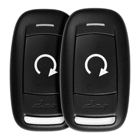
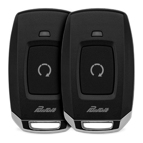
PRO9233Z_RevA_08/20
8
Detailed Descripons: Setup Opons
Security Control (Bank 2) (cont.) See page 11 for Programming Instrucon.
Feature 6: Door Trigger Delay
Funcon: Set the system to delay the door trigger acvaon input for ve (5) seconds
Seng Choices:
• Opon 1 - Instant - System will trigger instantly aer the door input is detected.
• Opon 2 - Delay - System will delay alarm trigger for ve (5) seconds aer door trigger input is detected.
Feature 5: Automac Arming
Funcon: Set the system to arm automacally aer exing the vehicle.
Seng Choices:
• Opon 1 - System will arm and doors will lock only when the alarm is armed from the remote control.
• Opon 2 - System will arm automacally 1 minute aer the last door is closed, and when the alarm is
armed from the remote control.
• Opon 3 - System will Arm and Lock doors automacally 1 minute aer the last door is closed, and when
the alarm is armed from the remote control.
Feature 9: Horn Output Duraon
Funcon: Set the horn output to acvate for a set me.
Seng Choices:
• Opon 1 - Output pulses for 16 milliseconds.
• Opon 2 - Output pulses for 30 milliseconds.
• Opon 3 - Output pulses for 40 milliseconds.
• Opon 4 - Output pulses for 50 milliseconds.
• Opon 5 - Output pulses for 10 milliseconds.
Feature 10: Override Method
Funcon: Set the Alarm Override Method. This will be used if the Remote is lost or inoperable.
Seng Choices:
• Opon 1 - Alarm Override method is normal. Ignion Key ON, press Valet buon one (1) me.
• Opon 2 - Alarm Override method is set for a Custom Code.
Feature 7: 1 or 2 Wire Disarm
Funcon: Set the disarm input detecon
Seng Choices:
• Opon 1 - 2 Wire Detecon, Will monitor Disarm input 1 and 2 for disarm pulse.
• Opon 2 - 1 Wire Disarm, Will monitor Disarm input 1 Only for pulse.
Feature 8: Nocaon Sounds
Funcon: Set the siren and/or horn to nofy when the system is armed or disarmed. (Siren Oponal)
Seng Choices:
• Opon 1 - Siren and horn will emit audible chirps when the system is armed and disarmed.
• Opon 2 - Siren will emit audible chirps when the system is armed and disarmed.
• Opon 3 - Horn will emit audible chirps when the system is armed and disarmed.
Note: Siren and horn will both sound if the system is triggered, regardless of this seng.

PRO9233Z_RevA_08/20 9
Security Control (Bank 2) (Cont.) See page 11 for Programming Instrucon.
Detailed Descripons: Setup Opons
Feature 12: Data Bus (DBI) Port Protocol
Funcon: Set funconality of the data bus connector to accept integraon modules of diering protocols.
Seng Choices:
• Opon 1 - The data bus connector will be congured to work with modules that use the ADS Protocol.
• Opon 2 - The data bus connector will be congured to work with modules that use the DBI Protocol.
Feature 11: Security Prole
Funcon: Set the system to funcon as a keyless entry / convenience system or full-featured alarm / convenience
system.
Seng Choices:
• Opon 1 - All security, keyless entry and convenience features are enabled.
• Opon 2 - Door Trigger zone is disabled.
• Opon 3 - Hood and Trunk Trigger zones are disabled.
• Opon 4 - All security trigger zones are disabled.
• Opon 5 - All security zones are enabled: Doors, Hood, and Trunk will be bypassed for ve (5) seconds
with Ignion ON ; Shock will be bypassed anyme Ignion is ON.
Feature 13: Disarm Input & Timing
Funcon: Set Arm and Disarm Input and Timing
Seng Choices:
• Opon 1 - System will disarm when a pulse of 120ms is detected on Disarm 1 only.
• Opon 2 - System will disarm when a pulse of 80ms is detected on Disarm 1 only
• Opon 3 - System will Disarm when a pulse of 120ms is detected on Disarm 1 & 2.
• Opon 4 - System will disarm when a pulse of 80ms is detected on Disarm 1 & 2.
Feature 14: Arm 1 Input Polarity
Funcon: Set the Arm 1 input polarity
Seng Choices:
• Opon 1 - System will Auto Detect the input polarity on power-up .
• Opon 2 - System will Arm when Posive (+) Pulse is detected.
• Opon 3 - System will Arm when Negave (-) pulse is detected.
Feature 15: Disarm 1 Input Polarity
Funcon: Set the Disarm 1 input polarity
Seng Choices:
• Opon 1 - System will Auto Detect the input polarity on power-up.
• Opon 2 - System will Disarm when Posive (+) Pulse is detected.
• Opon 3 - System will Disarm when Negave (-) pulse is detected.

PRO9233Z_RevA_08/20
10
Detailed Descripons: Setup Opons
Security Control (Bank 2) (Cont.) See page 11 for Programming Instrucon.
Feature 16: Arm 2 Input Polarity
Funcon: Set the Arm 2 input polarity
Seng Choices:
• Opon 1 - System will Auto Detect the input polarity on power-up .
• Opon 2 - System will Arm when Posive (+) Pulse is detected.
• Opon 3 - System will Arm when Negave (-) pulse is detected.
Feature 17: Disarm 2 Input Polarity
Funcon: Set the Disarm 2 input polarity
Seng Choices:
• Opon 1 - System will Auto Detect the input polarity on power-up .
• Opon 2 - System will Disarm when Posive (+) Pulse is detected.
• Opon 3 - System will Disarm when Negave (-) pulse is detected.
Feature 18: Trunk Shunt Input Polarity
Funcon: Set the Trunk Shunt input polarity
Seng Choices:
• Opon 1 - System will Auto Detect the input polarity on power-up .
• Opon 2 - System will Bypass the Trunk and Shock input when Posive (+) Pulse is detected.
• Opon 3 - System will Bypass the Trunk and Shock input when Negave (-) pulse is detected.
Feature 19: Dome Light Delay Timer
Funcon: Set the delay mer when using the vehicle's Dome Light as a door trigger.
Seng Choices:
• Opon 1 - OFF / Delay Timer will be OFF or use the programmed me. See page ## for dome light delay
programming procedure
• Opon 2 - 15 seconds, System will wait 15 seconds before monitoring the door trigger input.
• Opon 3 - 30 seconds, System will wait 30 seconds before monitoring the door trigger input.
• Opon 4 - 45 seconds, System will wait 45 seconds before monitoring the door trigger input.
• Opon 5 - 60 seconds, System will wait 60 seconds before monitoring the door trigger input.
• Opon 6 - 120 seconds, System will wait 120 seconds before monitoring the door trigger input.
Feature 20: Alarm Trigger Length
Funcon: Set the length of me the Alarm Nocaon will sound for each cycle.
Seng Choices:
• Opon 1 - 30 seconds, System will Alarm Cycle will sound for 30 second.
• Opon 2 - 45 seconds, System will Alarm Cycle will sound for 45 second.
• Opon 3 - 60 seconds, System will Alarm Cycle will sound for 60 second.
• Opon 4 - 90 seconds, System will Alarm Cycle will sound for 90 second.
• Opon 5 - 120 seconds, System will Alarm Cycle will sound for 120 second.
Note: The system will check the trigger inputs between each Alarm Cycle. If the trigger input is sll acve the system will
nofy the user with another cycle.

PRO9233Z_RevA_08/20 11
2= Bank 2
3= Bank 3
Ignition On
Ignition O
Press and Release
Override Button
1 Chirp = Bank 1
(Program Remotes)
Cycle Key to Advance
Banks (2,3)
Chirps Indicate
Bank Number
Chirps Indicate
Option Number
Press Override Button to
Advance Within Bank
Repeat Steps to Program
Another Feature Bank...
... or Exit
Programming
Press to Change
Feature Option
LED Indicates
Feature Selection
3X
Note: Programming will time out after 60sec with no activity or Ignition Off for 5sec.
1X
Repeat Steps to Program
Another Feature ...
L
O
C
K
A
C
C
O
N
S
T
A
R
T
L
O
C
K
A
C
C
O
N
S
T
A
R
T
L
O
C
K
A
C
C
O
N
S
T
A
R
T
Once the system is installed and powered up, you will use the vehicle ignion, override buon and a programmed
remote control to set all system opons. Feature opons are divided into categories, or Banks, as described throughout
this secon. Ensure that at least one remote control is programmed to the system. If not, or if you need to program
more remote controls, use the diagram steps to access Bank 1.
The horn/siren and LED will indicate your status and selecons. Follow the diagram below to enter and maneuver
through the programming procedure.
Quick Reference: System Programming
Programming Mode Entry and Exit Procedure
1. Turn the ignion ON.
2. Press and release the valet/override buon three (3) mes.
3. The system will chirp (1) one me, indicang you have accessed Bank 1.
4. Each cycle of the Ignion, OFF/ON, will advance to the next bank (up to Bank 3) then restart at Bank 2. (Note: To re-
access Bank 1 for transmier programming, you will need to exit and re-enter programming mode.)
5. The system will beep a number of mes to indicate the Bank number:
• 1 beeps: Bank 1 - NA
• 2 beeps: Bank 2 - Security Control Opons
6. Once you have accessed the desired bank, press the valet/override buon to advance though the features. The LED
will ash a number of mes to indicate the feature, based on the charts that follow this secon. The system will chip
a number of mes to indicate the Opon programmed.
7. Once you have accessed the desired feature, press the LOCK buon on the remote control to advance though the
feature's seng opons. The system will chirp a number of mes to indicate the Opon seng, based on the charts
that follow this secon.
8. Once you have made the desired seng, you can press the valet/override buon to advance through the
features within the bank, or cycle the Ignion key OFF/ON to advance to the next bank.
9. Once you have completed programming, you MUST turn the ignion key to OFF to exit the programming
mode. Programming will automacally exit aer 60 seconds of inacvity.

PRO9233Z_RevA_08/20
12
Bank 2: Security Opons See pages 7-10 for detailed descripons.
1 Chirp 2 Chirp
3 Chirp 4 Chirp 5 Chirp 6 Chirp
1 Lock / Unlock Func�on 500ms 3.5sec
500ms L, DBL UL DBL L, 500ms UL DBL L, DBL UL 500ms L, 350ms UL
2 Igni�on Lock OFF ON
3 Igni�on Unlock OFF ON
4 Auto Relock OFF Auto Lock Only
Auto Lock & Arm
5 Auto Arming / Locking OFF Auto Arm Only
Auto Lock & Arm
6 Door Trigger Instant Delay
7 1 or 2 Wire Disarm 2 Wire 1 Wire
8 No�fica�on Sound Both Siren Only
Horn Only
9 Horn Timing 16ms 30ms
40ms 50ms 10ms
10 Valet Override Method Valet Custom Code
11 Security Profile All On Doors Off
Hood/trunk OffAll OffAll ON w/ OEM RS
12 Data Port Protocol ADS DBI
13 Disarm Input 120ms Dr OR Pass 80ms Dr OR Pass 120ms, UL & Light 80ms, UL & Light
14 Arm 1 Input Auto Detect Posi�ve Nega�ve
15 Disarm 2 Input Auto Detect Posi�ve Nega�ve
16 Arm 2 Input Auto Detect Posi�ve Nega�ve
17 Disarm 2 Input Auto Detect Posi�ve Nega�ve
18 Trunk Shunt Input Auto Detect Posi�ve Nega�ve
19 Dome Light Delay Timer OFF / Program 15sec 30sec
45sec 60sec 120sec
20 Alarm Trigger Length 30sec 45sec 60sec
90sec 120sec
Feature Bank 2
Op�ons
Features
Data Port Protocol Selecon
The default data port protocol of this model is ADS (iDatalink 2-Way). This model is capable of detecng the correct
data port protocol (ADS or DBI) and automacally conguring Feature Bank 2; Feature 12. To inialize the detecon
procedure:
1. Press and hold the valet buon.
2. Cycle the vehicle’s Ignion ON/OFF two (2) mes.
3. Release the valet buon.
Dome Light Delay
To program the Pursuit system to wait unl the dome light turns o before arming:
1. Close all doors.
2. With the vehicle ignion o, press LOCK, UNLOCK, LOCK ,UNLOCK, LOCK, UNLOCK, LOCK on the remote control. The
dash-mounted LED will turn on.
2. Immediately OPEN then CLOSE the door WITHOUT disarming the system. Aer the dome light turns o, the LED will
ash to indicate programming compleon.
3. Disarm and exit the vehicle.
To return the system to default dome light sensing:
1. Turn the vehicle ignion ON then OFF three (3) mes, then press and hold the valet buon for ve (5) seconds.
2. The system will beep one (1) me indicang the learned delay has been cleared.
Quick Reference: System Programming & Diagnoscs

PRO9233Z_RevA_08/20 13
Quick Reference: System Programming & Diagnoscs
Silent Arm and Disarm
Program the Pursuit system to arm and disarm without nocaon chirps. (The horn/siren will sound if the system is
triggered while armed.)
1. Turn the ignion ON then OFF.
2. Press and release the valet/programming buon three (3) mes. The system will respond with one (1) chirp for ON or
two (2) chirps for OFF.
User Selectable LED
This feature will control whether the LED is ON or OFF when the system is Armed/Locked. This will be selectable in
feature programming OR on-the-y without entering the programming feature banks.
1. Turn the ignion ON, OFF, ON, OFF.
2. Press and hold valet buon for ve (5) seconds.
The system will respond with one (1) chirp for ON or two (2) chirps for OFF.
Adjusng the Shock Sensor
1. Arm the system, wait 5-10 seconds, then with an open palm carefully apply impact to areas of the vehicle to test the
shock sensor’s sensivity.
2. To adjust, turn the adjustment knob on the shock sensor counter-clockwise for less sensivity; clockwise for more
sensivity.
3. If the proper sensivity sll cannot be achieved, re-locate the shock sensor.
Troubleshoong Trigger Zones
Test the doors, hood, trunk, and shock sensor to ensure they trigger the security system. Once triggered, the LED ashes
to indicate the trigger source:
1 Shock
2 Trunk/Hood
3 Door

PRO9233Z_RevA_08/20
14
Quick Reference: Alarm Override Procedures
Valet Alarm Override
Custom Code Override
Unlike the default Valet Override, Custom Code Override is a user personalized code that oers a higher lever of security.
If the user chooses to use Custom Code Override, Feature Bank 2 ; Feature 9 must be programmed for "Custom Code".
Once the opon has been selected the code must be programmed. Once the Custom Code is programmed it cannot be
changed without rst disarming the alarm.
Custom Code Override Procedure
The Custom Code is made up of 2 numbers. Each chosen number must be between digits 1-9. The default Custom Code
is "11". To disarm the alarm using the Custom Code opon:
1. Turn the vehicle ignion to ON.
2. Within ve (5) seconds, Press the valet buon one (1) me.
3. Within ve (5) seconds, Turn the ignion OFF/ON.
4. Within ve (5) seconds, Press the valet buon one (1) me.
5. Turn the vehicle ignion to OFF then ON to start the vehicle.
Custom Code Programming Procedure
In this example, the user has selected Custom Code "23". To program a user selected custom code start with the alarm
disarmed:
1. Turn the ignion to the ON posion
2. Within ten (10) seconds, press the valet buon three (3) mes to enter programming.
3. Within ten (10) seconds, Cycle the ignion OFF/ON, OFF/ON, OFF/ON. The system will beep one (1) me.
4. Within ten (10) seconds, Press the valet buon two (2) mes. This number will indicate the rst digit of the chosen
Custom Code.
5. Within ten (10) seconds, Cycle the ignion OFF/ON.
6. Within ten (10) seconds, Press the valet buon three (3) mes. This number will indicate the second digit of the
chosen Custom Code.
7. Cycle the ignion OFF.
If the Custom Code was accepted the LED will ash the rst number (2), pause, then the second number (3). This will
repeat two (2) more mes to conrm the Custom Code entry. If aer 15sec the LED does not ash please repeat steps
1-7.
The Valet Override procedure will disable the alarm when the remote is not available or has become inoperave. If the
vehicle door is opened without disarming, the alarm will sound and the vehicle will not start when aempng to start
with the key. To disable the alarm:
1. Turn the vehicle ignion to ON.
2. Within ve (5) seconds, press and release valet buon one (1) me.
The alarm will silence and the vehicle will now start normally with the key.

PRO9233Z_RevA_08/20 15
Quick Reference: Wiring Diagrams
Door Lock Connecons
Posive-Trigger Door Locks
Vericaon: The vehicle wires register 12V+ when the Lock and Unlock switches are acvated.
Negave-Trigger Door Locks
Vericaon: The vehicle wires register Ground when the Lock and Unlock switches are acvated.
Lock
Unlock
Vehicle Door Lock
Control Relays
RED ( - ) Lock Output
GREEN ( - ) Unlock Output
Lock
Unlock
87
87a
86 85
30
87
87a
86 85
30
Vehicle Door Lock
Control Relays
Fused +12 Volt
Baery Souce
Fused +12 Volt
Baery Souce
RED ( - ) Lock Output
GREEN ( - ) Unlock Output

PRO9233Z_RevA_08/20
16
Quick Reference: Wiring Diagrams
Door Lock Connecons
Single-Wire Negave Mulplex Door Locks (Relays required)
Vericaon: The vehicle wire registers variable Ground values when the Lock and Unlock switches are acvated. Please
consult the vehicle-specic wire and locaon chart for resistor values.
Single-Wire Posive Mulplex Door Locks (Relays required)
Vericaon: The vehicle wire registers variable 12V+ values when the Lock and Unlock switches are acvated. Please
consult the vehicle-specic wire and locaon chart for resistor values.
Lock
Unlock
Vehicle Door Lock
Control Relays
RED ( - ) Lock Output Green ( - ) Unlock Output
87
87a
86
30
87
87a
86
30
85 85
Fused +12 Volt
Baery Source
Ground
Resistor
Lock
Unlock
Vehicle Door Lock
Control Relays
RED ( - ) Lock Output Green ( - ) Unlock Output
87
87a
86
30
87
87a
86
30
85 85
Fused +12 Volt
Baery Source
Resistor

PRO9233Z_RevA_08/20 17
Quick Reference: Wiring Diagrams
Door Lock Connecons
Reverse-Polarity Door Locks (Relays required)
Vericaon: The vehicle wires rest at Ground and register 12V+ when the Lock and Unlock switches are acvated.
Aermarket Actuators (Relays and door lock actuators required)
Lock
Unlock
87
87a
86 85
30
87
87a
86 85
30
Fused +12 Volt
Baery Souce
Fused +12 Volt
Baery Souce
RED ( - ) Lock Output
Green ( - ) Unlock Output
X
Cut
X
Cut
To Door Lock Motor
To Door Lock Motor
30
87
87a
86 85
Fused +12 Volt
Baer y Source
Door Lock
Actuator
30
87
87a
86 85
Chassis
Ground
Chassis
Ground
RED ( - ) Lock Output
GREEN ( - ) Unlock Output
Fused +12 Volt
Baer y Source
M

PRO9233Z_RevA_08/20
18
Quick Reference: Wiring Diagrams
Starter Kill / An-Grind Relay Connecons
Included Starter Kill / An-Grind Relay
L
O
C
K
A
C
C
O
N
S
T
A
R
T
CUT
87
87a
86 85
30
To Vehicle Ignion
To ORANGE - Starter Kill /
An-Grind Output (-) From Alarm

PRO9233Z_RevA_08/20 19
Quick Reference: Wiring Diagrams
1 White/Red Parking Light (87) Input (15A)
2 White Parking Light (30) Output
3 Red BaƩery 12V Input (+) (5A)
4 White/Black Siren Output (+)
5 Purple Door Trigger Input (+)
6 Yellow IgniƟon Input (+)
7 Lt. Green/White Illuminated Entry Output (-)
8 Black/White Horn Output (-)
9 Black Ground Input (-)
10 Orange Starter Kill Output (-)
11 Brown Door Trigger Input (-)
12 Lt. Green Trunk Trigger Input (-)
13 Gray/Black Hood Trigger Input (-)
14 Green/Lt. Blue AUX CH. 4 Output (-)
14 Pin Main
Replacement Part #4120546
VOXX
Replacement Part #4360975
Replacement Part #4120474
2 Red BaƩery 12V (+)
1 Blue LED Output (-)
LED
2 Gray Valet Switch Input (-)
1 Black Ground Output (-)
Valet
Replacement Part #4700033
1
2
3
4
4 Red BaƩery 12V (+)
3 Black Data TX
2 Green Warn AwayInput (-)
1 Blue Full TriggerInput (-)
Shock
2 Green Unlock Output (-)
1 Red Lock Output (-)
Door
Lock
Replacement Part #4120469
1
2
1 2 3 4
1 2 3 4
1 2 3 4 5
1
Blue Data TX
2White Data RX
3 Black Ground (-)
4 Red
BaƩery 12V (+)
CarLink
1
White Data RX
2Black Ground (-)
3 Blue Data TX
4 Red BaƩery 12V (+)
DBI
1Green/Black Arm 2 (+/-)
2Red/Yellow Disarm 1 (+/-)
3 Green/Yellow Arm 1 (+/-)
4 Red/Black Disarm 2 (+/-)
5Blue Trunk Shunt (+/-)
Control
1234567891011 12 13 14
Replacement Part #4120547
Not Included
Not Included
Shock Sensor
Part #4700033
Table of contents
Other PURSUIT Remote Starter manuals

PURSUIT
PURSUIT PRO9233E User manual

PURSUIT
PURSUIT PRO9051Z User manual

PURSUIT
PURSUIT PR71TW User manual

PURSUIT
PURSUIT PRO9776Z User manual

PURSUIT
PURSUIT PRO9556Z Installation and operating manual

PURSUIT
PURSUIT PRO9556E User manual

PURSUIT
PURSUIT PRO9056Z User manual

PURSUIT
PURSUIT PRO9556Z User manual

PURSUIT
PURSUIT PR1BZ User manual

PURSUIT
PURSUIT PRORS User manual