PushCorp AFD1100 User manual

Wet-Sander
AFD1100
Manual
PAR01330-2January, 2000
Dallas, Texas

CAUTION
DO NOT spin the Servo Sanding Motor
without supplying water
CAUTION
Active Force Devices contain calibrated
electronics.
HANDLE WITH CARE DO NOT DROP
DO NOT USE LUBRICATED AIR.
This device requires a dry, non-lubricated
80 to 90 psi (5.5 – 6.2 bar) air supply
filtered to 5 µm and a 0.3 micron oil mist
separator.
Non-compliance with these requirements
will void the manufacturer’s warranty.
(See Section 4.3)
All fasteners, mounting holes and pipe
threads on this tool are METRIC.
All PushCorp, Inc. electrical cables are rated for
high twist and flex robotic applications with a
minimum cable bending radius specification of
125mm (5 in). Cable damage resulting from
failure to abide by this specification will not be
covered under warranty.

AWS1100 Wet Sander Manual
Table of Contents
1.0 LIMITED WARRANTY .........................................................................................1
2.0 GENERAL OVERVIEW........................................................................................3
3.0 INSTALLATION...................................................................................................4
3.1 Mounting the AWS1100 ....................................................................................................................4
3.2 Air Supply..........................................................................................................................................5
3.3 Water Connections ...........................................................................................................................7
3.4 Electrical Connections.......................................................................................................................8
4.0 Wetsanding Pad Removal and Replacement...................................................................................8
4.0 TECHNICAL SPECIFICATIONS..........................................................................9

AWS1100 Wet Sander Manual 1
Copyright PushCorp, Inc. 2000. All rights reserved.
1.0 Limited Warranty
Duration:
One year from date of delivery to the original purchaser.
Who gives this warranty (warrantor):
PushCorp, Inc.
Telephone: (972) 840-0208
Corporate Address:
P. O. Box 181915
Dallas, Texas 75218
Shipping Address:
3001 W. Kingsley Rd.
Garland, Texas 75041
Who receives this warranty (purchaser):
The original purchaser (other than for purposes of resale) of the PushCorp, Inc.
product
What products are covered by this warranty:
Any PushCorp, Inc. industrial equipment or accessory supplied or
manufactured by the Warrantor.
What is covered under this warranty:
Defects in material and/or workmanship, which occur within the duration of the
warranty period.
What is NOT covered in this warranty:
A. IMPLIED WARRANTIES, INCLUDING THOSE OF MERCHANT-ABILITY
AND FITNESS FOR A PARTICULAR PURPOSE ARE LIMITED TO ONE
YEAR FROM THE DATE OF ORIGINAL PURCHASE. Some states do not
allow limitations on how long an implied warranty lasts, so the above
limitations may not apply to you.
B. ANY INCIDENTAL, INDIRECT, OR CONSEQUENTIAL LOSS, DAMAGE
or EXPENSE THAT MAY RESULT FROM ANY DEFECT, FAILURE,
MALFUNCTION OF THE PUSHCORP, INC. PRODUCT. Some states do
not allow the exclusion or limitation of incidental or consequential damages
so the above limitation or exclusion may not apply to you.
C. Any failure that results from an accident, purchaser's abuse, neglect,
unauthorized repair or failure to operate the products in accordance with
the instructions provided in the owner's manual(s) supplied with the
product.
Responsibilities of the Warrantor under this warranty:
Repair or replace, at Warrantor's option, products or components which have
failed within the duration of the warranty period.

AWS1100 Wet Sander Manual 2
Copyright PushCorp, Inc. 2000. All rights reserved.
Responsibilities of the purchaser under this warranty:
A. Deliver or ship the PushCorp, Inc. product or component to PushCorp, Inc.
Service Center, Dallas, TX. Freight and insurance costs, if any, must be
borne by the purchaser.
B. Use reasonable care in the operation and maintenance of the product as
described in the owner's manual(s).
When warrantor will perform repair or replacement under this warranty:
Repair or replacement will be scheduled and serviced according to the normal
workflow at the service center, and depending on the availability of
replacement parts. Purchasers requiring quicker repair may receive such with
payment of a PushCorp, Inc. predetermined expediting fee.
This Limited Warranty gives you specific legal rights and you may also have other
rights, which vary, from state to state.

AWS1100 Wet Sander Manual 3
Copyright PushCorp, Inc. 2000. All rights reserved.
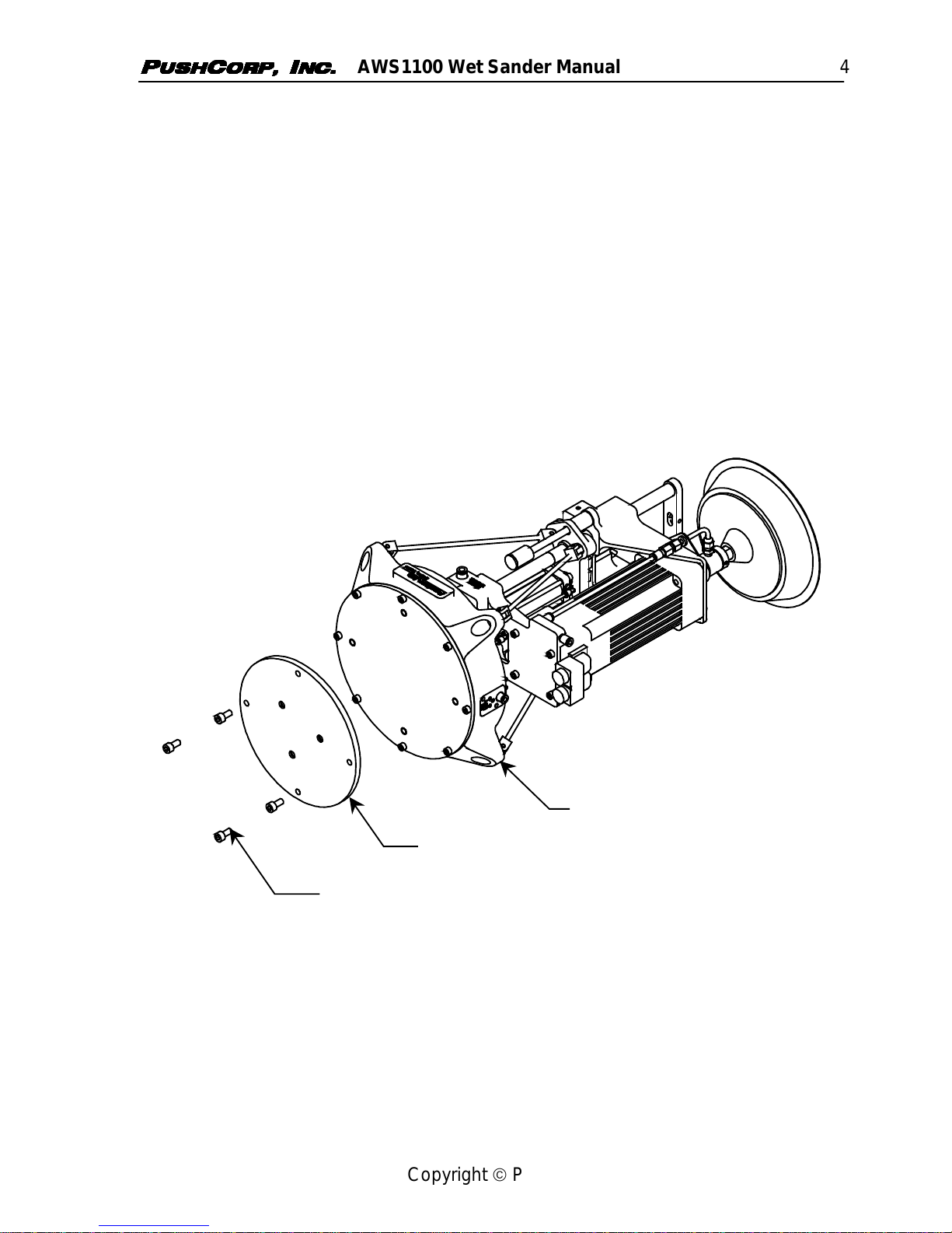
2.0 General Overview
The PushCorp, Inc. AWS1100 Wet Sander and FCU1000 Active Compliance
Controller (US Patent No. 5,448,146) provide a superior robotic surface finishing
system. The AWS1100 is an end of arm robotic device specifically designed to
perform wet sanding operations. The Wet Sander system enables a robot to
manipulate an abrasive media over any contoured surface with an extremely precise,
consistent, compliant force. This unique capability gives the robot the ability to excel
in a traditionally expensive and inconsistent manual process. The Wet Sander
coupled with a robot delivers results that are virtually impossible to duplicate with a
manual operation.
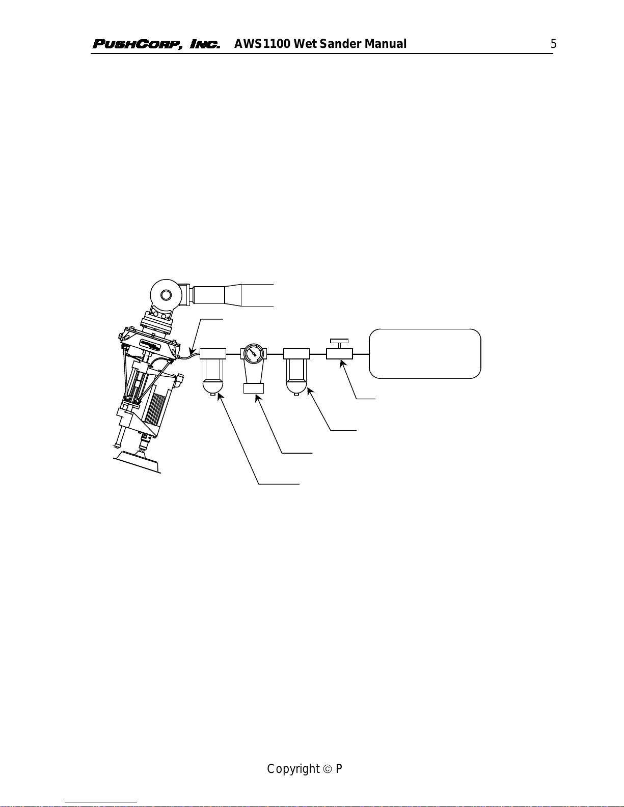
To achieve this superior performance, the AWS1100 Wet Sander utilizes PushCorp
patented active force control technology. This technology is realized through the use
of a pneumatic actuator to provide the sanding force and a load-cell force sensor to
provide closed-loop feedback to the control unit. The pneumatic actuator provides the
force and necessary compliance by moving the sanding motor along linear rods.
These linear rods allow a 3.0 inch (80mm) stroke enabling the sanding pads to remain
in contact with the part, and apply the correct force, regardless of any robot/part
misalignment. Also, the AWS1100 contains an accelerometer that monitors the
spacial orientation and allows the unit to automatically compensate for gravitational
and inertial effects to maintain the desired sanding force. Finally, a linear
potentiometer, located within the pneumatic actuator, senses the position of the Wet
Sander motor along the linear rods.
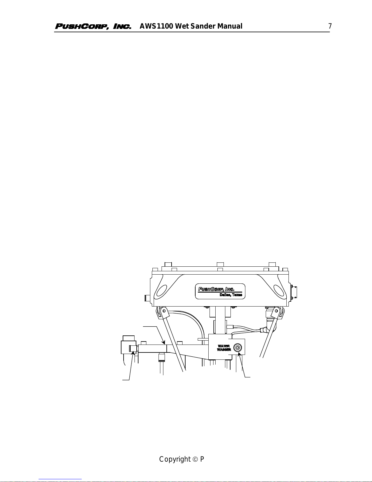
The AWS1100 has several unique features to endure the harsh conditions found in a
typical wet sanding environment. A primary feature is that AWS1100 is water-
resistant, allowing the tool to be washed down. The tool’s main linear bearings are
hydrostatic and float on Stainless Steel linear rods using water pressure. This method
has been chosen to resist rust and corrosion while maintaining the low friction
required for precise force control. All of the electronics are sealed in the base housing
to prevent any water contamination.
The AWS1100 is equipped with a variable speed servo sanding motor. The motor is
controllable over a -6200 to +6200 rpm speed range. The servo sanding motor is also
equipped with an integral water feed-through to supply the abrasive pad with flooding
capability.
To control the AWS1100 Wet Sander the FCU1000 Active Compliance Controller
must be used. The unit contains a high-speed microprocessor executing proprietary
control algorithms. The microprocessor controller provides several advanced features
including automatic motor/tool weighing, automatic motor weight/gravity
compensation, and automatic compensation of acceleration induced forces. To
facilitate system integration, a remote host computer or PLC controller can be
interfaced through high level communications including RS-232 serial, 24 VDC
parallel, or analog interfaces.

AWS1100 Wet Sander Manual 4
Copyright PushCorp, Inc. 2000. All rights reserved.
3.0 Installation
3.1 Mounting the AWS1100
The AWS1100 Wet Sander attaches to the robot’s mounting flange. The Wet Sander
is supplied with a removable Mounting Plate. PushCorp, Inc. can provide the
Mounting Plate blank, or with a customer specified bolt-hole pattern.
A minimum of three flat-head screws (user supplied) is required to securely attach the
Mounting Plate to the robot’s mounting flange. These flat-head screws must be
installed per the robot manufacturer's instructions.
To mount an AWS1100 first remove the (4) four M8 fasteners that secure the
Mounting Plate to the Base. The Mounting Plate is attached to the robot, with the
user supplied flat-head fasteners. Then align the AWS1100 Base with the Mounting
Plate, and re-install the (4) four M8 fasteners. Torque the M8 fasteners to the value
listed in Section 6.0.
Mounting Plate
M8 Fastener
Base
Figure 1. AWS1100 Mounting Scheme

AWS1100 Wet Sander Manual 5
Copyright PushCorp, Inc. 2000. All rights reserved.
3.2 Pneumatic Connection
The AWS1100 Wet Sander requires a dry, non-lubricated, filtered, 80 psi (5.5 bar) to
90 psi (6.2 bar) air supply. The device requires a maximum flow rate of 2.0 cfm (56.6
l/m). Failure to provide supply air to these specifications can degrade performance
and will void any warranty repairs concerning pneumatic components. A minimum 80
psi (5.5 bar) air pressure must be maintained for the device to operate within
published specifications. Operating at lower air pressure can cause inferior force
control performance and possibly instability. Operating the AWS1100 at pressures
over 90 psi (6.9 bar) will activate a pressure relief valve inside the Base. This valve
prevents damage to the load cell due to operating the unit with excessive pressure.
This relief valve is strictly a protective mechanism and should not be used as a
pressure regulator device.
The Air Supply System should be configured as shown in Figure 2.
3µm OIL/MIST SEPARATOR
AIR REGULATOR/PRESSURE GAUGE
5µm FILTER
SHUT-OFF VALVE
80 psi (5.5 bar) TO
90 psi (6.2 bar), DRY,
NON-LUBRICATED,
AIR SUPPLY
¼ inch (6mm) AIR SUPPLY LINE
Figure 2. Pneumatic Configuration
If water condensation is a problem in your air supply system, an air dryer device is
highly recommended. The ideal solution is an industrial chiller dryer capable of
reducing the dewpoint to less than 32°F (0°C). Moisture inside the force device will
cause premature failure that will not be covered under warranty.
The AWS1100 Air Supply Port is located on the Wet Sander Base. The port is
labeled “AIR (LUFT)”. Improper connection to the port will result in failure of the
pneumatic and electronic components in the Wet Sander. (See Figure 3) A 6mm
tube push-lock fitting is supplied, but if another type of fitting is desired, unscrew the
existing fitting and replace it with a suitable fitting having a Rc 1/8 (metric) thread. Be
sure to use a thread seal product and do not over tighten the fitting.

AWS1100 Wet Sander Manual 6
Copyright PushCorp, Inc. 2000. All rights reserved.
AIR SUPPLY PORT
BASE
Figure 3. AWS1100 Air Supply Port.
The single Air Supply Line to the device should be ¼ inch (6mm) diameter flexible
polyurethane tubing. The tubing should be routed to the AWS1100 such that there
are no kinks and that there is plenty of slack to allow for any desired manipulator
motion. Before attaching the Air Supply Line to the unit, open the Shut-Off Valve to
blow out any contaminates which may be in the tubing. Attach the tubing to the Wet
Sander Air Supply fitting. Charge the system with compressed air and verify that
there are no air leaks and that there is a minimum of 80 psi (5.5 bar) at the Air Supply
Port. If a minimum air pressure of 80 psi (5.5 bar) cannot be achieved, then an
auxiliary air compressor or booster pump must be installed.
To remove the Air Supply Line, first release all air pressure in the system. Then, if
using the PushCorp supplied push-lock fitting, push inward on the fitting's ring, then
pull the tubing out. Cover or plug the push-lock fitting any time the Air Supply Line is
not connected. This will keep any contaminants from entering the unit.
NOTE: PushCorp highly recommends the use of flexible polyurethane tubing as
opposed to nylon tubing. This is because nylon tubing tends to crimp shut
when it is bent. This severely limits airflow and may cause erratic operation.
Polyurethane tubing is designed to withstand continuous bending cycles and
resist crimping.

AWS1100 Wet Sander Manual 7
Copyright PushCorp, Inc. 2000. All rights reserved.
3.3 Water Connections
The Wet Sander has been designed to operate with standard tap or deionized water.
The water supply to the Wet Sander must be clean and free of contamination to
ensure proper operation. A water filter is required.
Figure 4 shows the (2) water connections on the AWS1100. The first water
connection on the Wet Sander Frame is a 8mm Push-lock Fitting, labeled “WATER
(WASSER)”. The Hydrostatic Bearing Water Input supplies the hydrostatic bearings.
The hydrostatic bearings require pressurized water to provide the force to separate
the bearing from the round linear shaft. The greater the water pressure, the greater
the bearing load capacity. The AWS1100 requires a minimum 60 psi (4.2 bar) to a
maximum 100 psi (6.8 bar) water pressure. Without proper water pressure, the
bearing will come into contact with the linear shaft and cause excessive friction and
force errors. The second connection is an 8mm push-lock fitting, supplying water to
the Servo Motor Water Feedthru.
CAUTION: Operating the AWS1100 servomotor without supplying water to the
water feed bearings could result in bearing failure.
The Wet Sander water connections are supplied with 8mm tube push-lock fittings, but
if another type of fitting is desired, unscrew the existing fitting and replace it with a
suitable fitting having a Rc 1/8 (metric) thread. Be sure to use a thread seal product
and do not over tighten the fitting.
The Water Supply Lines to the Wet Sander should be flexible polyurethane tubing.
The tubing should be routed to the AWS1100 such that there are no kinks and that
there is plenty of slack to allow for any desired manipulator motion.
WET SANDER FRAME
SERVO MOTOR
WATER FEEDTHRU
8MM TUBING
HYDROSTATIC BEARING
WATER INPUT
8MM TUBING
Figure 4. AWS1100 Water Connections

AWS1100 Wet Sander Manual 8
Copyright PushCorp, Inc. 2000. All rights reserved.
3.4 Electrical Connections
Figure 5 shows the electrical cable connections for the AWS1100 Wet Sander. For
additional instructions concerning the FCU1000 Controller Cable, please refer to the
FCU1000 Manual. Please refer to the KollmorgenServo Motor documentation for
detailed information regarding motor connections and setup.
MOTOR POWER CABLE
MOTOR FEEDBACK CABLE
CONTROLLER CABLE
Figure 5. Electrical Cable Connections
4.0 Wetsanding Pad Removal and Replacement
The AWS1100 Wet Sander accepts standard 5/8–11 right-hand threaded wet-sanding
pads.
To remove a worn Wet Sanding Pad from the AWS1100 first ensure all power to the
Wet-Sander and Robot is disconnected. Then use an open-end wrench to hold the
18mm Wrench Flats on the Wet Sander Shaft. The Wet Sanding Pad may then be
unscrewed. A new Wet Sanding Pad can then be threaded onto the Wet Sander
shaft. See Figure 6.
WET SANDING PAD
5/8 – 11 UNF RIGHT-HAND THREADS
18mm WRENCH FLATSSERVO SANDING MOTOR
WET SANDER SHAFT
Figure 6. Wet Sanding Pad Removal and Replacement

AWS1100 Wet Sander Manual 9
Copyright PushCorp, Inc. 2000. All rights reserved.
5.0 Technical Specifications
Maximum Applied Force: 100 lb. (444 N)
Force Resolution: +/-0.5 lb. (+/-2.2 N)
Compliant Stroke: 3 in. (76 mm)
Servo Motor: 3.8 hp (2.8 kW)
6200 rpm
Weight: 48 lb. (22.8 kg)
Temperature: 50°to 122°F (10°to 50°C)
Humidity: 5% to 95%, Non-Condensing
Supply air: Non-lubricated, Dry, 5µm Filtered, 80-90 psi (5.5-6.2 bar)
2 SCFM (28 l/min)
Hydrostatic Bearing: 60 psi (4.1 bar) Min., 100 psi (6.9 bar) Max.
Water Pressure
Specifications subject to change without notice.
Fastener Tightening Torque Specs
Torque Minimum Depth
Fastener Size in.-lbs. ft.-lbs. N·m in. mm
M4 x .7 50 4.2 5.6 0.17 4.3
M5 x .8 85 7.1 9.6 0.21 5.3
M6 x 1 140 11.7 15.8 0.25 6.3
M8 x 1.25 348 29.0 39.3 0.33 8.4
M10 x 1.5 600 50.0 67.8 0.41 10.5
Table of contents