Putzmeister SP11 LMR User manual

Operating Instructions
Translation of the original Operating Instructions
for machine operator and maintenance staff
always keep by the machine
Motar machine SP11 LMR
Machine no.
Rev. 00--041 PMM_3653750 6

Putzmeister
Mörtelmaschinen
GmbH
Max–Eyth–Str. 10
D–726 1 Aichtal
Postfach 2152
D–72629 Aichtal
07127 / 599–0
Hotline:
(07127) 599--699
07127 / 599 74
www.putzmeister.de
e--mail:
Internet:

Contents
I
1 About these Operating Instructions
1.1 Foreword 1 —............................................
1. Iconsandsymbols 1 — 4...................................
Safety Regulations
.1 Principle —............................................
Onwardssale —.....................................
. Designateduse — 3......................................
.3 Use contrary to the designated use — 4. . . . . . . . . . . . . . . . . . . . .
Extending delivery line — 4. . . . . . . . . . . . . . . . . . . . . . . . . . . . .
Modifications — 4......................................
.4 Liability — 5.............................................
Exclusion of liability — 5. . . . . . . . . . . . . . . . . . . . . . . . . . . . . . . .
.5 Personnel selection and qualifications — 6. . . . . . . . . . . . . . . . . .
Training — 6...........................................
Qualified electrician — 6. . . . . . . . . . . . . . . . . . . . . . . . . . . . . . . .
Hydraulics technician — 6. . . . . . . . . . . . . . . . . . . . . . . . . . . . . .
.6 Sourcesofdanger — 7....................................
Hot machine components — 7. . . . . . . . . . . . . . . . . . . . . . . . . . .
Delivery line and coupling system — 7. . . . . . . . . . . . . . . . . . . .
.7 Safetyequipment — 8.....................................
.8 Personal protective clothing — 9. . . . . . . . . . . . . . . . . . . . . . . . . . .
.9 Risk of injury -- residual risk — 11. . . . . . . . . . . . . . . . . . . . . . . . . . . .
.10 Risk of crushing and bumping — 1. . . . . . . . . . . . . . . . . . . . . . . . .
Transporting the machine — 1. . . . . . . . . . . . . . . . . . . . . . . . . . .
Assembly of the auger pump — 13. . . . . . . . . . . . . . . . . . . . . . . .
.11 Electricalcontact — 14.....................................
.1 Risk of burns and scalding — 15. . . . . . . . . . . . . . . . . . . . . . . . . . . .
Hydraulicfluid — 15.....................................
Coolant — 16...........................................
.13 Startingup — 17..........................................
.14 Blockage — 18............................................

Contents
II
.15 Hydraulic and pneumatic equipment — 19. . . . . . . . . . . . . . . . . . . .
Check — 19............................................
Dumpingpressure — 0.................................
Bleeding — 0..........................................
.16 Placeofwork — 1........................................
Operator — 1..........................................
.17 Workingarea — 1........................................
.18 Conduct in emergencies — 1. . . . . . . . . . . . . . . . . . . . . . . . . . . . . .
.19 Noisepollution — 1.......................................
Operator — 1..........................................
. 0 Environmental protection —. . . . . . . . . . . . . . . . . . . . . . . . . . . . . .
. 1 Spareparts —..........................................
. Storingthemachine —..................................
. 3 Soundemissions — 3.....................................
Operator — 3..........................................
. 4 Placeofwork — 4........................................
Machineoperator — 4..................................
High-pressure gun operator — 4. . . . . . . . . . . . . . . . . . . . . . . . .
. 5 Workingarea — 4........................................
. 6 Conduct in an emergency — 4. . . . . . . . . . . . . . . . . . . . . . . . . . . . .
. 7 Accessories — 5.........................................
. 8 Storingthemachine — 5..................................
. 9 Injuries through unauthorised starting or use of the machine — 6
.30 Safety-related parts (SRP) — 7. . . . . . . . . . . . . . . . . . . . . . . . . . . . .
.31 Spareparts — 8..........................................
Labelling of safety-related parts in the spare parts sheets — 8
Spare delivery of safety-related parts — 8. . . . . . . . . . . . . . . . .

Contents
III
3 General Technical Description
3.1 Machineversions 3 — 1.....................................
3. Machine designation 3 —. . . . . . . . . . . . . . . . . . . . . . . . . . . . . . . . . .
3.3 Machinemodel 3 —......................................
3.4 Machinenumber 3 —.....................................
3.5 Summary 3 — 3............................................
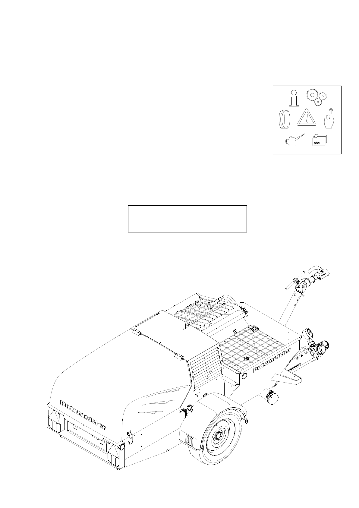
Machine 3 — 3..........................................
Enginecompartment 3 — 4...............................
3.6 Technicaldata 3 — 5.......................................
Dimensions 3 — 5.......................................
Weight 3 — 5...........................................
Chassis 3 — 5...........................................
Tyres 3 — 5.............................................
Performancedata 3 — 6..................................
Fluidcapacities 3 — 7....................................
3.7 Ratingplate 3 — 8.........................................
3.8 Soundpowerlevel 3 — 9....................................
3.9 Safetyequipment 3 — 10.....................................
EMERGENCY STOP button 3 — 10. . . . . . . . . . . . . . . . . . . . . . . . .
Hoodsafetydevice 3 — 11................................
Protectivegrilles 3 — 11...................................
Safetyswitch 3 — 11......................................
3.10 Functional description 3 — 1. . . . . . . . . . . . . . . . . . . . . . . . . . . . . . . .
General set-up of the machine 3 — 1. . . . . . . . . . . . . . . . . . . . . .
3.11 Controlcabinet 3 — 13.......................................
3.1 Engine 3 — 15..............................................
3.13 Augerpump 3 — 16.........................................
3.14 Hydrauliccontrol 3 — 17.....................................
Hydraulic control block SP11 3 — 18. . . . . . . . . . . . . . . . . . . . . . . .
3.15 Compressor 3 — 19.........................................
3.16 Airvalvefitting 3 — 0.......................................
3.17 Spraygun 3 — 1...........................................
3.18 Dust extraction (option) 3 —. . . . . . . . . . . . . . . . . . . . . . . . . . . . . . .
3.19 High-pressure cleaner (option) 3 — 3. . . . . . . . . . . . . . . . . . . . . . . . .

Contents
IV
4 Transport, Set-up and Connection
4.1 Transportanddriving 4 — 1.................................
4. Transporting the machine 4 —. . . . . . . . . . . . . . . . . . . . . . . . . . . . .
4.3 Machine transport position 4 — 3. . . . . . . . . . . . . . . . . . . . . . . . . . . .
4.4 Beforeajourney 4 — 4......................................
Groundclearance 4 — 4.................................
Towinggear 4 — 5.......................................
Transportposition 4 — 5..................................
Adjusting the towing gear 4 — 6. . . . . . . . . . . . . . . . . . . . . . . . . . .
Ballhitch 4 — 7.........................................
Couplingtheballhitch 4 — 7..............................
Disconnecting the ball hitch 4 — 9. . . . . . . . . . . . . . . . . . . . . . . . .
Permitted slewing circle of the ball hitch 4 — 10. . . . . . . . . . . . . .
Permitteddrawbarload 4 — 10.............................
4.5 Lightingequipment 4 — 11...................................
4.6 Selecting the set-up site 4 — 1. . . . . . . . . . . . . . . . . . . . . . . . . . . . . . .
4.7 Set-up site requirements 4 — 1. . . . . . . . . . . . . . . . . . . . . . . . . . . . . .
Supportingground 4 — 1.................................
Lighting 4 — 1..........................................
4.8 Settingup 4 — 13...........................................
Inclinationangles 4 — 13..................................
Aligningthemachine 4 — 14...............................
4.9 Waterconnections 4 — 15....................................

Contents
V
5 Starting up
5.1 Checks 5 —.............................................
Visualchecks 5 —.....................................
Operatingmaterials 5 — 3................................
Fuellevel 5 — 4.........................................
Engineoillevel 5 — 4....................................
Compressor oil level 5 — 5. . . . . . . . . . . . . . . . . . . . . . . . . . . . . . .
Hydraulic fluid level 5 — 5. . . . . . . . . . . . . . . . . . . . . . . . . . . . . . . .
Coolantlevel 5 — 6......................................
Checking cooling fins on the radiator 5 — 6. . . . . . . . . . . . . . . . .
5. Refuelling the machine 5 — 7. . . . . . . . . . . . . . . . . . . . . . . . . . . . . . . .
5.3 Testrun 5 — 8.............................................
Startingtheengine 5 — 8.................................
5.4 Functionchecks 5 — 11......................................
Checking the function of the safety equipment 5 — 11. . . . . . . .
Function check of EMERGENCY STOP button 5 — 1. . . . . . . . .
Function check of hood safety device 5 — 13. . . . . . . . . . . . . . . .
Function check of the protective grille cut-out 5 — 14. . . . . . . . .
Pumpfunctions 5 — 16....................................
Mixerfunctions 5 — 16....................................
5.5 Thedeliveryline 5 — 17......................................
5.6 Shutting down machine after initial operation 5 — 18. . . . . . . . . . . . .

Contents
VI
6 Operation
6.1 Requirements 6 — 1........................................
6. Emergency shut-down procedures 6 —. . . . . . . . . . . . . . . . . . . . .
EMERGENCYSTOPbutton 6 —.........................
6.3 Initialpumping 6 — 4.......................................
6.4 Adjusting the auger pump 6 — 5. . . . . . . . . . . . . . . . . . . . . . . . . . . . .
6.5 Raising / lowering the lifting mixer unit 6 — 6. . . . . . . . . . . . . . . . . .
6.6 Pumpingoperations 6 — 8..................................
6.7 Pumping 6 — 9............................................
6.8 Outputregulation 6 — 10.....................................
6.9 Breaksinpumping 6 — 11...................................
6.10 Blockages 6 — 1...........................................
Rectifyingblockages 6 — 1...............................
6.11 Usingthespraygun 6 — 13..................................
Adjusting the air nozzle tube 6 — 14. . . . . . . . . . . . . . . . . . . . . . . .
Practicaltip 6 — 15.......................................
6.1 Cleaningthemachine 6 — 16.................................
Informationoncleaning 6 — 16.............................
Machine 6 — 18..........................................
Deliveryline 6 — 19.......................................
Spraygun 6 —........................................
6.13 High-pressure cleaner (optional) 6 — 3. . . . . . . . . . . . . . . . . . . . . . .
7 Faults, Cause and Remedy
7.1 Machine,general 7 —.....................................
7. Electricalsystem 7 — 1.....................................
7.3 Chassis 7 — 14.............................................

Contents
VII
8 Maintenance
8.1 Maintenance intervals 8 —. . . . . . . . . . . . . . . . . . . . . . . . . . . . . . . . .
8. Other risks during maintenance work 8 — 1. . . . . . . . . . . . . . . . . . .
Personal protective clothing 8 — 1. . . . . . . . . . . . . . . . . . . . . . . . .
Personnel requirements 8 — 1. . . . . . . . . . . . . . . . . . . . . . . . . . . . .
Otherrisks 8 — 13........................................
8.3 Operating materials 8 — 15. . . . . . . . . . . . . . . . . . . . . . . . . . . . . . . . . . .
Fuel 8 — 16..............................................
Engineoil 8 — 17.........................................
Coolant 8 — 17...........................................
Hydraulicoil 8 — 18.......................................
Compressoroil 8 — 18....................................
Mixerbearing 8 — 19.....................................
Axleandwheels 8 — 19...................................
High-pressure cleaner (option) 8 — 19. . . . . . . . . . . . . . . . . . . . . .
8.4 Maintenance work in the engine compartment 8 — 0. . . . . . . . . . .
Maintenance Chart
40--066 Lubrication diagram 8 — 5. . . . . . . . . . . . . . . . . . . . . . . . .
41--003 Cleaning the solenoids 8 — 7. . . . . . . . . . . . . . . . . . . . . . .
41--011 Checking acid level in the battery 8 — 30. . . . . . . . . . . . .
44--019 Changing the oil in the compressor 8 — 3. . . . . . . . . . . .
44--059 Changing the engine oil and engine oil filter 8 — 35. . . .
44--06 Checking and replacing hydraulic hoses 8 — 39. . . . . . .
44--090 Changing the coolant 8 — 44. . . . . . . . . . . . . . . . . . . . . . . .
44--09 Changing the hydraulic fluid 8 — 47. . . . . . . . . . . . . . . . . .
44--093 Changing the hydraulic filter 8 — 5. . . . . . . . . . . . . . . . . .
44--095 Antifreeze protection for the radiator 8 — 56. . . . . . . . . . .
44--096 Cleaning and changing the dry air filter 8 — 58. . . . . . . .
44--137 Cleaning the radiator 8 — 61. . . . . . . . . . . . . . . . . . . . . . . .
44--138 Checking the V-belt 8 — 64. . . . . . . . . . . . . . . . . . . . . . . . .
44--140 Fuelfilter 8 — 66...................................
46--0 7 Disassembly and assembly of the auger pump 8 — 71.
46--0 8 Adjusting the auger pump 8 — 76. . . . . . . . . . . . . . . . . . . .

Contents
VIII
46--030 Replacing the screw conveyor 8 — 79. . . . . . . . . . . . . . . .
5 --008 High-pressure cleaner 8 — 81. . . . . . . . . . . . . . . . . . . . . . .
5 --010 Water supply fitting antifreeze protection 8 — 83. . . . . . .
5 --0 6 High-pressure cleaner antifreeze
protectionmeasures 8 — 86.........................
9 Decommissioning
9.1 Temporary decommissioning 9 — 1. . . . . . . . . . . . . . . . . . . . . . . . . .
Shutting the machine down 9 —. . . . . . . . . . . . . . . . . . . . . . . . .
Fillingupthefueltank 9 —..............................
Frostprotection 9 —....................................
9. Final decommissioning, disposal 9 — 3. . . . . . . . . . . . . . . . . . . . . . .
Materialused 9 — 4......................................
Parts requiring separate disposal 9 — 4. . . . . . . . . . . . . . . . . . . .
10 Appendix
10.1 General tightening torques 10— 1. . . . . . . . . . . . . . . . . . . . . . . . . . . .
10. Lubricant recommendation 10— 3. . . . . . . . . . . . . . . . . . . . . . . . . . . .
10.3 The correct mortar mixture 10— 6. . . . . . . . . . . . . . . . . . . . . . . . . . . . .
10.4 Template for EC declaration of conformity 10— 10. . . . . . . . . . . . . . .
Index of Key Words

About these Operating Instructions
1 — 1
01_0001_0505GB
1 About these Operating Instructions
In this chapter you will find notes and information that will help you
use these Operating Instructions. Do not hesitate to contact us if you
have any queries:
Putzmeister Mörtelmaschinen GmbH
Postfach 15
D-7 6 9 Aichtal, Germany
Tel: +49 (0)71 7 599-0
Fax: +49 (0)71 7 599-743
Internet: http://www.moertelmaschinen.de
E-mail: pmm@pmw.de
or the branch or services agent responsible for you.
Address:
Telephone:
Fax:
E-mail:

About these Operating Instructions
1 —
01_0001_0505GB
These Operating Instructions are intended to familiarise the user with
the machine and to assist him in using the machine properly in va-
rious possible applications.
The Operating Instructions contain important information on how to
operate the machine safely, properly and economically. Taking these
instructions into consideration will help
-- to avoid dangers,
-- to reduce repair costs and downtimes,
-- to increase the reliability and service life of the machine.
The Operating Instructions must be supplemented by the relevant
national rules and regulations for accident prevention and environ-
mental protection.
The Operating Instructions must always be available wherever the
machine is in use.
The machine owner must make the location of these Operating In-
structions known to all personnel charged with performing jobs on
the machine and ensure they are accessible. These operating in-
structions must be read and applied by any person who carries out
work with or on the machine, e.g.
-- operation, including setting up, fault rectification in the course of
work, removal of production waste, care and disposal of fuels and
consumables,
-- service (maintenance, inspection, repair), and/or
-- transport.
The generally recognised rules of technology for safe and proper
working must be observed in addition to the Operating Instructions
and mandatory rules and regulations for accident prevention and
environmental protection in the country and place of use of the ma-
chine.
Continuation next side
1.1 Foreword

About these Operating Instructions
1 — 3
01_0001_0505GB
The Branch or Agent serving you, or the Aichtal Works, will be happy
to give you more information, should you have any questions follo-
wing your study of the Operating Instructions.
You will make it much easier for us to answer any questions if you
can give us the details of the machine model and the machine num-
ber.
These operating instructions do not include a description of the drive
motor; please refer to the operating instructions provided by the mo-
tor manufacturer.
Modifications are made from time to time in the interests of constant
improvement and it could be possible that we were unable to take
these into consideration when these Operating Instructions were
printed.
These operating instructions are not covered by the Amendment Ser-
vice of Putzmeister Mörtelmaschinen GmbH. Alterations may be
made to these operating instructions without prior notification.
The contents of this document may not be reproduced, even in part,
without our written permission. All technical data, drawings, etc. are
protected by copyright law.
The pages are divided into chapters where they are numbered con-
secutively.
Example: Page 3--
Chapter 3
Page
Copyright by

About these Operating Instructions
1 — 4
01_0001_0505GB
The following icons and symbols are used in the Operating Instruc-
tions:
"Action symbol
Text following this symbol describes tasks which you are required to
work through, generally in the sequence shown from top to bottom.
⇒Text after this icon describes the result or the effect of an
activity.
Refer also to the maintenance charts:
This symbol is used to refer to the maintenance charts required, pos-
sibly as a supplement to the maintenance charts you are currently
reading.
The following special tool is required:
This icon identifies the special tools necessary to carry out the work.
Normal tools, i. e. standard tools or tools carried in the vehicle are
not listed additionally.
Environmental protection
This symbol is used to identify tasks during which particular attention
is to be paid to environmental protection. The associated text is writ-
ten in italics and is closed off with a line.
Notes
Particular specifications with regard to the economic use of the ma-
chine are introduced with the word ”Note” and the pictogram illustra-
ted. The associated text is written in italics and is closed off with
a line.
Caution
Particular specifications or instructions and prohibitions with regard
to the prevention of damage are introduced with the word ”Caution”
in bold and the pictogram illustrated. The associated text is written in
italics and is closed off with a line.
Continuation next side
1.2 Icons and symbols

About these Operating Instructions
1 — 5
01_0001_0505GB
Danger
Particular specifications or instructions and prohibitions with regard
to the prevention of personal injury or significant damage are introdu-
ced with the pictogram illustrated the word ”Danger” written in bold
and a line. The associated text is written in italics and is closed off
with a line.
The appropriate symbol will be used if it is possible to identify the
source of the danger precisely.
Suspended Load
This symbol is used to identify tasks in which suspended loads may
fall down.
Danger of crushing
This symbol is used to identify tasks during which there is the danger
of being crushed.
Heavy current
This symbol is used to identify tasks in which there is the danger of
electrocution possibly with lethal consequences.


Safety Regulations
— 1
03_0001_0505GB
2 Safety Regulations
This chapter summarises the most important safety regulations. This
Chapter must be read and understood by all persons who handle
the machine. The various regulations are also repeated once more at
the appropriate points in the Operating Instructions.
Notes
Special safety regulations may be necessary for some tasks. These
special safety regulations will only be found in the description of the
particular task.
The following safety instructions should be regarded as a supple-
ment to already existing valid national accident prevention regula-
tions and laws.
Existing accident prevention regulations and laws must be observed
in all cases.

Safety Regulations
—
03_0018_0809GB
Use only machines in a technically perfect condition, as designated
and being conscious of safety and the dangers, taking account of
the Operating Instructions. Any faults, especially those affecting the
safety of the machine, must, therefore, be rectified immediately.
Make sure that
-- no safety equipment is removed, rendered inoperable or modified,
-- safety equipment removed for the purposes of maintenance work
is refitted immediately after the work is completed.
Check operational safety every time you start work. Any defects
found or suspected must be eliminated immediately. If necessary,
inform the project supervisor.
If defects or faults are found or suspected during operation, opera-
tion must cease immediately. Eliminate the defect or fault before re-
starting.
The following should be noted if you sell the machine on:
Pass on to the new operator all the accompanying documentation
(Operating Instructions, Maintenance Instructions, diagrams, inspec-
tion certificates etc.) you received with your machine. If necessary,
you may have to order the papers from us, quoting the machine
number. The machine may not be sold on without the accompanying
documentation under any circumstances.
Reporting an onwards sale or acquisition to Putzmeister ensures
that you will be sent any information relating to modifications or in-
novations relevant to safety, and you will also be eligible for technical
consultancy from our works.
2.1 Principle
Onwards sale

Safety Regulations
— 3
03_0058_0511GB
The machine has been built in accordance with the state of the art
and recognised safety rules. Nevertheless, its use may constitute a
risk to life and limb of the operator or of third parties, or cause da-
mage to the machine and to other property.
The machine must only be used as specified in the Operating In-
structions and the enclosed documentation. All information and sa-
fety regulations in the Operating Instructions must be observed.
The auger pump SP 11 is designed exclusively to mix and pump
premixed dry mortar and site mixes of up to 6 mm grain size through
hose lines with 50 mm maximum diameter.
Performance must be restricted to pumping operations on building
sites. The maximum delivery pressure must not be higher than that
specified on the rating plate or in Technical Data.
The delivery line through which the pump is to deliver must be desi-
gned for the delivery pressure and installed and secured correctly
in accordance with recognised technical regulations.
Filling of the auger pump is carried out in the reservoir / hopper.
Any protective covers belonging to the machine should be attached
before operation.
The machine must be operated only with the safety equipment fitted.
Specified inspection work should be carried out at regular intervals.
Any work on the electric or hydraulic unit of the machine must be
carried out only by trained and qualified hydraulic and electrotechni-
cal specialists.
Never make any modifications, additions or conversions to the ma-
chine without first obtaining the manufacturer’s approval.
The machine must be inspected for operational safety by a technical
expert at least once a year. The operator is responsible for commis-
sioning the inspection.
2.2 Designated use

Safety Regulations
— 4
03_01 3_0808GB
Use of the machine other than described in the section ”Designated
use”, or which goes beyond such use, is considered contrary to the
designated use. Putzmeister Mörtelmaschinen GmbH accepts no
liability for damage resulting from such use. The risk of such misuse
lies entirely with the machine operator.
Extending the delivery line beyond the length specified in the techni-
cal data is prohibited.
A new delivery line is only suitable for pressures entered on the ra-
ting plate.
Never make any modifications, additions or conversions to the ma-
chine which might affect safety without first obtaining the manufactu-
rer’s approval. This also applies to the installation and adjustment of
safety devices and valves as well as to welding work on load--bea-
ring elements.
The values quoted on the rating plate and in the technical data are
the maximum permissible values.
The control and safety settings made at Putzmeister Mörtelmaschi-
nen GmbH must not be changed.
The machine must not be operated with deactivated, modified or de-
fective safety devices.
Safety devices must only be repaired, adjusted or replaced by tech-
nically qualified experts.
All devices of relevance for safety must be in place and fully functio-
nal.
2. Use contrary to the
designated use
Extending delivery line
Modifications
Table of contents
Other Putzmeister Water Pump manuals
Popular Water Pump manuals by other brands

DROPSA
DROPSA 3417000 Series manual

Commodity Axis
Commodity Axis ViaAqua MillionAir MA 80 manual

Wilo
Wilo Helix EXCEL 1004-2/25/V/KS,DN40,2.2kW Installation and operating instructions

Lincoln
Lincoln SKF FlowMaster II A Series User and maintenance instructions

Beckett
Beckett FR Series manual

Vetus
Vetus GWDS Installation and user manual