PXM PX232 User manual

MANUAL
1 Relay
Module
PX232
R

CONTENTS
1
1
2
3
4
5
5
6
1. General description.............................................................................................
2. Safety conditions.................................................................................................
3. Connections and control elements description....................................................
4. DMX address settings.........................................................................................
5. Connection Diagram............................................................................................
6. Technical Drawing ..............................................................................................
7. Technical Data ....................................................................................................
8. Declaration of Conformity....................................................................................
Manufacturer reserves the right to make modifications in order to improve device operation.
PXM s.c.
ul. Przemysłowa 12
30-701 Kraków
POLAND
tel.: (+48 12) 626 46 92
fax: (+48 12) 626 46 94
E-mail: [email protected]
Internet: www.pxm.pl

1
The PX232 Relay Module is a device used to switch effects of stage and architectural illuminators
via DMX-512 signal.
The module contains a transmitter that controls the on / off output. It has a built-in hysteresis,
which eliminates vibration of relay phenomena during switching on and off. The PX232 switches
on output when the DMX value is over 191. Relay switches off the output after reaching 64 value
or below.
Method of hysteresis operation is shown below.
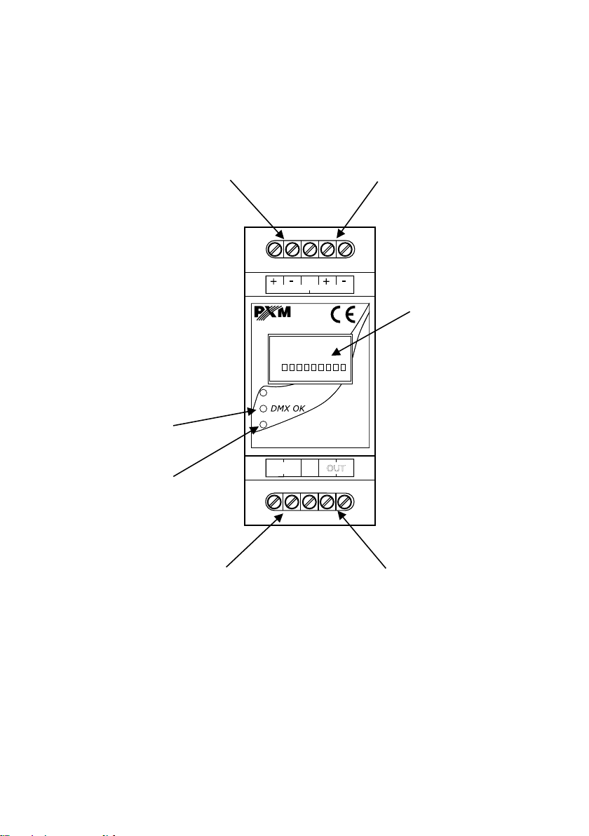
The device is equipped with DMX signal input and output. Its housing is adapted for mounting on
DIN rails and is 35 mm wide (the size of 2-modules).
1. GENERAL DESCRIPTION
2. SAFETY CONDITIONS
The PX232 is a device powered directly from power grid 230V, what may result in electric shock
in case of not following safety rules. During its installation and use the following rules must be
strictly observed:
1. Installation of the device should be carried out by a person with appropriate qualifications in
accordance with this document.
2. The electrical outlet to which the switch is connected have to be linked to a working protective
installation (3-wire installation.)
3. Protect the power cord from mechanical and thermal damage.
4. In case of damage the power cord, cable, replace it with the same technical data and
certificates.
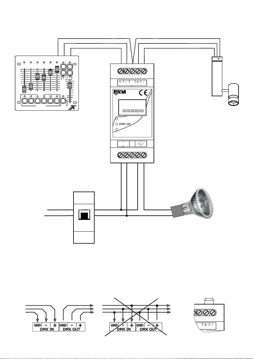
5. For connecting devices to the 1 Relay Module use only 3-wire cables with cross-section of not
less than 1.5 mm.
6. Connection of DMX signal can only be made with shielded conductor.
7. All repairs and connections of outputs or DMX signal can only be made with cut off power
supply.
8. PX215 should be strictly protected against contact with water and other liquids.
9. All sudden shocks, particularly dropping, should be avoided.
10. The device cannot be turned on in places with humidity exceeding 90%.
o o
11. The device cannot be used in places with temperature lower than 2 C or higher than 40 C.
12. Clean it with damp duster only.
OFF
ON
DMX value
64
0191

2
3. CONNECTION AND CONTROL ELEMENTS DESCRIPTION
DMX-512
Output
DMX
dipswitches
address
Power supply
DMX-512
Input
Output
control diode
DMX signal
control diode
On/Off type output
www.pxm.pl
L N
230 VAC
DMX IN
PX 232
DMX OUT
GND
POWER
OUT
On
1 2 3 4 5 6 7 8 9
On

3
1
2
3
4
5
6
7
8
9
10
11
12
13
14
70
71
72
73
74
100
101
102
103
104
105
249
250
251
2 3 4 5 6 7 8 9
ON DIP
1 2 3 4 5 6 7 8 9
ON DIP
1 2 3 4 5 6 7 8 9
ON DIP
1
2 3 4 5 6 7 8 9
ON DIP
1 2 3 4 5 6 7 8 9
ON DIP
1
2
2
2
2
2
2
2
2
3
3
3
3
3
3
3
3
4
4
4
4
4
4
4
4
5
5
5
5
5
5
5
5
6
6
6
6
6
6
6
6
7
7
7
7
7
7
7
7
8
8
8
8
8
8
8
8
9
9
9
9
9
9
9
9
ON
ON
ON
ON
ON
ON
ON
ON
DIP
DIP
DIP
DIP
DIP
DIP
DIP
DIP
1
1
1
1
1
1
1
1
2
2
3
3
4
4
5
5
6
6
7
7
8
8
9
9
ON
ON
DIP
DIP
1
1
2
2
2
2
2
3
3
3
3
3
4
4
4
4
4
5
5
5
5
5
6
6
6
6
6
7
7
7
7
7
8
8
8
8
8
9
9
9
9
9
ON
ON
ON
ON
ON
DIP
DIP
DIP
DIP
DIP
1
1
1
1
1
2
2
2
2
2
3
3
3
3
3
4
4
4
4
4
5
5
5
5
5
6
6
6
6
6
7
7
7
7
7
8
8
8
8
8
9
9
9
9
9
ON
ON
ON
ON
ON
DIP
DIP
DIP
DIP
DIP
1
1
1
1
1
2
2
2
3
3
3
4
4
4
5
5
5
6
6
6
7
7
7
8
8
8
9
9
9
ON
ON
ON
DIP
DIP
DIP
1
1
1
4. DMX ADDRESS SETTINGS
The PX232 allows to set an address on a single DMX channel. The start address is set in binary
code using a switch-type "DIP switch". Here are some sample settings for the start address.
2
ON
1
On
Off
White color shows position of the switch . In
upper position DIP switch is ON and in lower
position it is OFF.

4
5. CONNECTION DIAGRAM
1 2 3 4 5 6
PX015
1 2 3 4 5 6 Chaser Scene
Club 6p
90
% 100
80
70
60
50
40
30
20
10
0
100 %
90
80
70
60
50
40
30
20
10
0
Master
MusicSpeed
DMX controller efect (ex. lamp)
ex. halogen
lamp
230 V AC N
L
www.pxm.pl
L N
230 VAC
DMX IN
PX 232
DMX OUT
GND
POWER
OUT
GND
N
L
Residual Current Circuit Breaker
(RCCD) - 6A
PX232 must be connected to the DMX line in series. This means that to the DMX IN terminal
control cable should be connected, and then from the DMX OUT terminal the control cable should
go to other DMX receivers.
If the PX232 is the last device in the DMX line, to the terminals "DMX + " and "DMX-" have to be
connected the terminator - 110 Ohm resistor (between pin "+" and "-"DMX Out).
110 Ohm
DMX OUT
GND
CORRECT WRONG
DMX-512 Input DMX-512 Output DMX Cord

511
1
max. 6A, 250V AC / channel
terminal blocks
230V AC
max. 16 mA
35 mm (2-modules)
60 mm
85 mm
- DMX channels:
- Number of output channels:
- Output load:
- Connections:
- Power supply:
- Current consumtion:
- Dimensions: Width:
Height:
Lenght:
7. TECHNICAL DATA
5
35 mm
85 mm
58 mm
www.pxm.pl
L N
230 VAC
DMX IN DMX OUT
GND
6. TECHNICAL SCHEME

6
PXM s.c.
ul. Przemysłowa 12
30-701 Kraków
Poland
1 Relay Module
PX232
PN-EN 60065
PN-EN 61000-6-1
PN-EN 61000-6-3
Marek Żupnik M.Sc., Eng.
The DMX-512 connection have to be shielded and the
shielding must be connected to the ground responding to
the DMX connectors.
Name of producer:
Address of producer:
declares that the product:
Name of product:
Type:
answers the following product specifications:
LVD:
EMC:
Additional informations:
Kraków, 13.11.2009
DECLARATION OF CONFORMITY
according to guide lines 2006/95/WE and 2004/108/WE
stage and theatre consoles digital dimmers dmx systems architectural lighting controllers led lighting
tel: +48 12 626 46 92
fax: +48 12 626 46 94 e-mail: [email protected]
http://www.pxm.pl
ul. Przemysłowa 12
30-701 Kraków, Poland
Other manuals for PX232
1
This manual suits for next models
1
Table of contents
Other PXM Relay manuals
Popular Relay manuals by other brands

GE
GE IRT51E instructions

Ei Electronics
Ei Electronics RadioLINK Relay Module Ei428 instruction manual

Thytronic
Thytronic NA10 manual

Siemens
Siemens SIRIUS 3RA2811 Original operating instructions

Siemens
Siemens SIMOCODE pro Original operating instructions

Siemens
Siemens 3MH70 Series operating instructions