Pyramid Technical Consultants CP15AF User manual
CP15AF & CP15AL
Pulse pre-amplifiers
User Manual
Pyramid Technical Consultants, Inc.
135 Beaver Street Suite 102, Waltham MA 02452 USA
US: TEL: (781) 402 1700 FAX: (781) 402-1750 EMAIL:
Europe: TEL: +44 1273 492002

PTC System Controls and Diagnostics
CP15 User Manual CP15_UM_221017 Page 2 of 33
1 Contents
1
Contents .............................................................................................................................................................. 2
2
Table of Figures .................................................................................................................................................. 4
3
Safety Information ............................................................................................................................................. 5
4
Models ................................................................................................................................................................. 7
5
Scope of Supply .................................................................................................................................................. 8
6
Optional Items .................................................................................................................................................... 9
6.1
Power supplies and adaptors .......................................................................................................................... 9
6.2
Cables and adaptors ........................................................................................................................................ 9
7
Intended Use and Key Features ...................................................................................................................... 10
7.1
Intended Use .................................................................................................................................................. 10
7.2
Key Features ................................................................................................................................................. 10
8
Specification ...................................................................................................................................................... 11
9
Installation ........................................................................................................................................................ 15
9.1
Mounting ....................................................................................................................................................... 15
9.2
Grounding and power supply ........................................................................................................................ 15
9.3
Connection to equipment ............................................................................................................................... 15
9.3.1
Typical setup ........................................................................................................................................ 15
9.3.2
Setup with the C400 ............................................................................................................................. 16
9.3.3
Effect of cable length ........................................................................................................................... 17
10
Comparison of CP15AF and CP15AL ........................................................................................................... 18
11
Circuit overview ............................................................................................................................................... 20
12
Setup and Calibration ...................................................................................................................................... 22

PTC System Controls and Diagnostics
CP15 User Manual CP15_UM_221017 Page 3 of 33
12.1
Gain setting .............................................................................................................................................. 22
12.2
Offset correction ....................................................................................................................................... 22
12.3
Conversion gain ........................................................................................................................................ 23
12.4
Energy calibration .................................................................................................................................... 24
13
Connectors, controls and indicators ............................................................................................................... 26
13.1
Input end connectors, controls and indicators ......................................................................................... 26
13.2
Output end connectors .............................................................................................................................. 26
13.2.1
Out .................................................................................................................................................. 26
13.2.2
Power +/- 12 V ................................................................................................................................ 26
13.3
Internal settings ........................................................................................................................................ 27
14
Fault-finding ..................................................................................................................................................... 28
15
Maintenance ..................................................................................................................................................... 30
16
Returns procedure ........................................................................................................................................... 31
17
Support.............................................................................................................................................................. 31
18
Disposal ............................................................................................................................................................. 31
19
Declaration of Conformity .............................................................................................................................. 32
20
Revision History ............................................................................................................................................... 33

PTC System Controls and Diagnostics
CP15 User Manual CP15_UM_221017 Page 4 of 33
2 Table of Figures
Figure 1. CP15 case end panels. Dimensions mm. ................................................................................................... 13
Figure 2. CP15 underside (showing mounting holes) and side views. Dimensions mm. .......................................... 14
Figure 3. Schematic CP15 installation for readout of a scintillation detector ............................................................. 16
Figure 4. Using the CP15 with the C400 .................................................................................................................... 16
Figure 5. Effect of input cable length on output pulse amplitude and rms noise level ............................................... 17
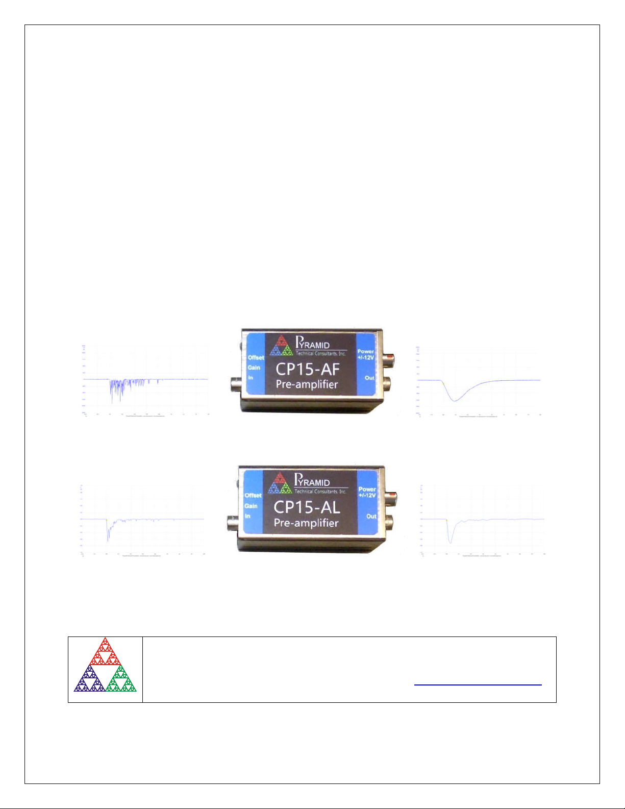
Figure 6 Output for a single 59.6 keV X-ray event from a NaI detector (left) and a LaCl
3
detector (right) measured
with a high bandwidth CP10B preamp; 1 µsec per division. ............................................................................. 18
Figure 7 Single output for a 59.6 keV X-ray event from a NaI detector (left) and a LaCl
3
(right) measured with
CP15AF preamp; 1 µsec per division. ............................................................................................................... 18
Figure 8 Single output for a 59.6 keV X-ray event from a NaI detector (left) and a LaCl
3
(right) measured with
CP15AL preamp; 1 µsec per division. ............................................................................................................... 19
Figure 9. CP15AF simplified block schematic. .......................................................................................................... 20
Figure 10. CP15AL simplified block schematic .......................................................................................................... 20
Figure 11 CP15AF increasing gain setting, showing saturation onset in the final view ............................................. 22
Figure 12 Adjusting offset after adjusting gain for CP15AF ...................................................................................... 23
Figure 13 Setup for conversion gain calibration ......................................................................................................... 23
Figure 14 Square wave into test capacitor and resulting charge pulses measured by the CP15. ................................ 23
Figure 15. Measured pulse height spectrum for Am-241 gammas, NaI scintillation detector and CP15AF ............. 24
Figure 16. Determination of energy by scaling .......................................................................................................... 25
Figure 17. Location of internal jumpers; left CP15AF, right CP15AL....................................................................... 27

PTC System Controls and Diagnostics
CP15 User Manual CP15_UM_221017 Page 5 of 33
3 Safety Information
CP15 preamplifiers are designed for compliance with harmonized electrical safety standard
EN61010-1:2000. It must be used in accordance with its specifications and operating
instructions. Operators of the unit are expected to be qualified personnel who are aware of
electrical safety issues. The customer’s Responsible Body, as defined in the standard, must
ensure that operators are provided with the appropriate equipment and training.
The unit is designed to make measurements in Measurement Category I as defined in the
standard.
Although the CP15 does not generate dangerous voltages, nor are they designed to measure
directly such voltages, they may be in applications where such voltages are present. Appropriate
precautions must be taken.
The unit should not be operated unless correctly assembled in its case. Only Service Personnel,
as defined in EN61010-1, should attempt to work on the disassembled unit, and then only under
specific instruction from Pyramid Technical Consultants, Inc. or their authorized distributors.
The unit is designed to operate from +/- 12 VDC power rails, with a maximum current
requirement of 70 mV on each rail for the CP15. Up to four CP pre-amplifiers can be powered
by one C400 pulse counting detector controller. CP pre-amplifiers can also be used in a mixture
with the CP15 charge sensitive pre-amplifier / shaping amplifier.
The CP pre-amplifier should be grounded by secure connection to a grounded conducting
surface. If the unit is mounted on an insulating surface, then one of the four mounting screw
locations must be re-assigned as a grounding connection.
Some of the following symbols may be displayed on the unit and have the indicated meanings.

PTC System Controls and Diagnostics
CP15 User Manual CP15_UM_221017 Page 6 of 33
Direct current
Earth (ground) terminal
Protective conductor terminal
Frame or chassis terminal
Equipotentiality
Supply ON
Supply OFF
CAUTION – RISK OF ELECTRIC SHOCK
CAUTION – RISK OF DANGER – REFER TO MANUAL

PTC System Controls and Diagnostics
CP15 User Manual CP15_UM_221017 Page 7 of 33
4 Models
CP15AF Variable gain pulse pre-amplifier optimized for use with sodium
iodide scintillation detectors.
(FMB-Oxford part CP-15N)
CP15AL Variable gain pulse pre-amplifier optimized for use with lanthanum
bromide or lanthanum chloride scintillation detectors.
(FMB-Oxford part CP-15L)
The following options for the CP15AL and CP15AF can be requested at time of order. Jumper
settings can be set in the field by trained service personnel.
-I/NI Overall inverting or non-inverting (default is inverting so that
photomultiplier pulses give positive-going pulses)

PTC System Controls and Diagnostics
CP15 User Manual CP15_UM_221017 Page 8 of 33
5 Scope of Supply
CP15 model as specified in your order.
USB memory stick containing:
Data sheet
User manual
Test results
Optional items as specified in your order, such as power supplies, cables and adaptors.
PTC System Controls and Diagnostics
CP15 User Manual CP15_UM_221017 Page 9 of 33
6 Optional Items
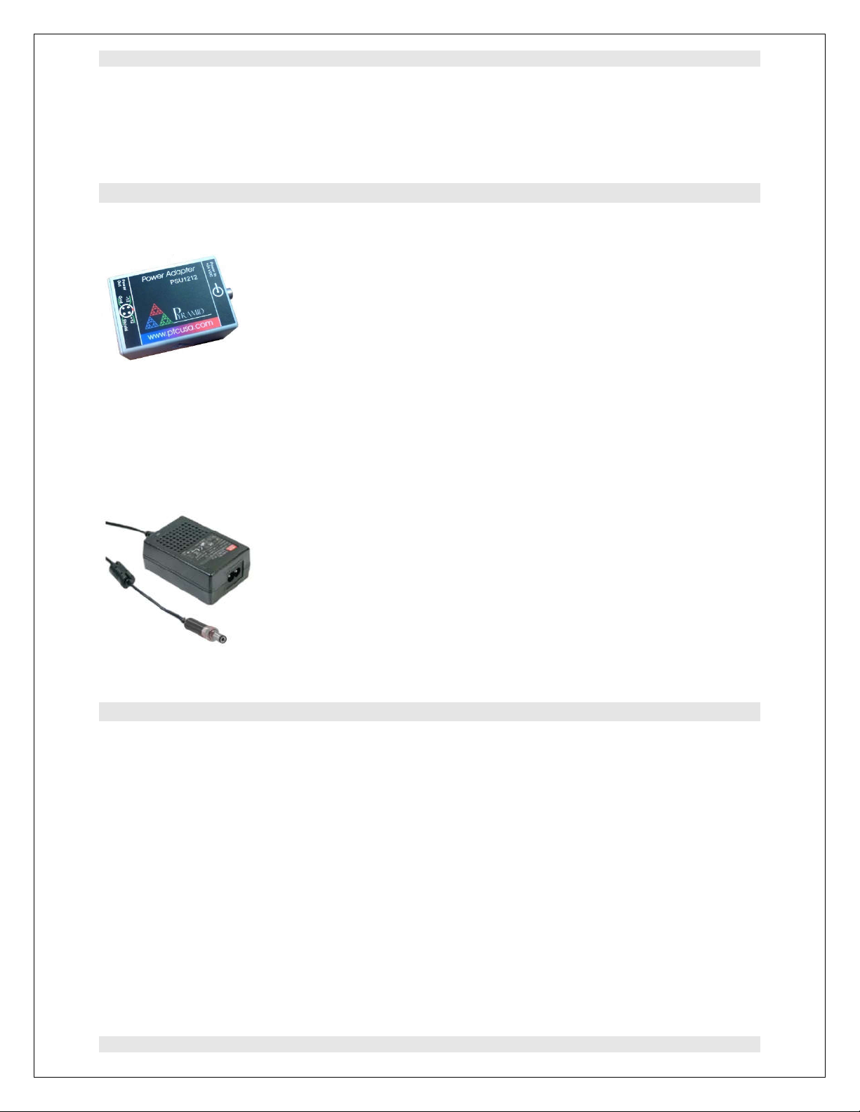
6.1 Power supplies and adaptors
PSU1212-L. +24 VDC to +/-12 VDC power supply, input for 2.1mm threaded jack, output 4 pin
Lemo 0B.304.
PSU1212-C. +24 VDC to +/-12 VDC power supply, input for 2.1mm threaded jack, output 9 pin
DSub female with pinout matching C400 connectors.
PSU1212-N. +24 VDC to +/-12 VDC power supply, input for 2.1mm threaded jack, output 9
pin DSub female with pinout matching NIM standard pre-amp power connectors,
PSU24-25-1. Universal 24 VDC PSU, 25 W, 100-240 VAC 50-60 Hz input via IEC C8
connector, S671K threaded jack output.
Note: If the CP15 is used with a C400, +/-12V power is provided by the C400.
6.2 Cables and adaptors
CAB-L00-10-L00 Lemo 00 coax cable assembly, 10’ (3 m). For signal output.
CAB-L00-30-L00 Lemo 00 coax cable assembly, 30’ (9 m). For signal output.
CAB-L304M-10-D9M Power cable assembly, 10’ (3 m). To power CP1x from PSU1212 or
C400.
CAB-L304M-30-D9M Power cable assembly, 30’ (9 m). To power CP1x from PSU-B12 or
C400.
ADAP-LEMO-BNC Adaptor, Lemo 00 coax plug to BNC jack. For signal output if using
BNC-terminated cables.
Other lengths available on request.

PTC System Controls and Diagnostics
CP15 User Manual CP15_UM_221017 Page 10 of 33
7 Intended Use and Key Features
7.1 Intended Use
The CP15 models are intended to amplify and condition charge pulses generated by scintillation
detectors based on photomultipliers. Other detectors that produce similar charge pulses can also
use the CP15. The output is suitable for delivery to discriminator circuits and counters, or to
multichannel analysers for pulse height spectral analysis. The C400 fast discriminator/counter is
able to connect up to four detectors and CP15 pre-amplifiers and provides all necessary low
voltage power and high voltage bias.
The CP15AF (also known as the CP-15N in FMB-Oxford Ltd installations) has gain and filtering
suited to sodium iodide (NaI(Tl)) scintillation detectors. The burst of fast charge pulses from a
single detection event is converted to a single smooth output pulse, well-suited to discrimination
or pulse height analysis.
The CP15AL (also known as the CP-15L in FMB-Oxford Ltd installations) as gain and filtering
suited to lanthanum bromide (LaBr
3
) and lanthanum chloride (LaCl
3
) scintillation detectors.
These detectors are considerably faster than sodium iodide detectors (and more expensive) and
are preferred for higher count rates. The CP15AL has a corresponding faster response, using
filtering that provides a single output pulse per detection event but without compromising pulse
pair resolution.
7.2 Key Features
Very compact and cost-effective unit with three DC-coupled amplification stages.
Gain and offset control trimpots
Fully bipolar; output can be inverted if required so that output pulses are always positive
polarity.
Filtering suited to sodium iodide (CP15AF) or lanthanum halide (CP15AL) scintillation
detectors.
Tolerant of long signal input cables.
Output able to drive a 50 ohm load.
Compatible with Pyramid C400 pulse counting detector controller.
This manual suits for next models
1
Table of contents


