Qcells Q.HOME CORE H4 User guide

INSTALLATION QUICK GUIDE
Q.HOME CORE
H4/A4/H5 /A5
EnglishFrançaisDeutsch

English
This quick guide explains how to install Q.HOME CORE H4 /A4/H5/A5.
Please note that the screenshots in this quick guide may differ from the actual
software screen due to possible updates and version changes that occur after
publication. In addition, the information provided in this manual is subject to
change without prior notice. For more details on any pertinent updates, please
contact either the service provider or technical support.
Contact
Hanwha Solutions Corp.
Q CELLS 86 Cheonggyecheon-ro Jung-gu Seoul Korea 04541
Q.HOME ESS Service for Europe, Germany
E-Service Haberkorn GmbH, Augustenhöhe 7, 06493 Harzgerode
TEL: +49 (0)39484 9763 85 / EMAIL: q.home@e-service48.com
Hanwha Q CELLS Australia Pty Ltd
Suite 1, Level 1, 15 Blue Street, North Sydney NSW 2060 Australia
TEL: +61 (0)2 9016 3033 / EMAIL: qhome.au@q-cells.com
Copyrights
Copyright and intellectual property rights of all content and diagrams in the
manual belong to Hanwha Solutions Corp.
Illegal use, duplication, distribution, or dissemination of the manual for
purposes not intended by Hanwha Solutions Corp. is strictly prohibited and
such activity is an infringement of the intellectual property rights of Hanwha
Solutions.
© 2021 Hanwha Solutions Corp. All rights reserved.

English
Contents
1 Downloading Manuals ............................................................................ 5
2 Symbols Used........................................................................................... 5
3 Safety........................................................................................................... 5
4 Requirements ............................................................................................ 6
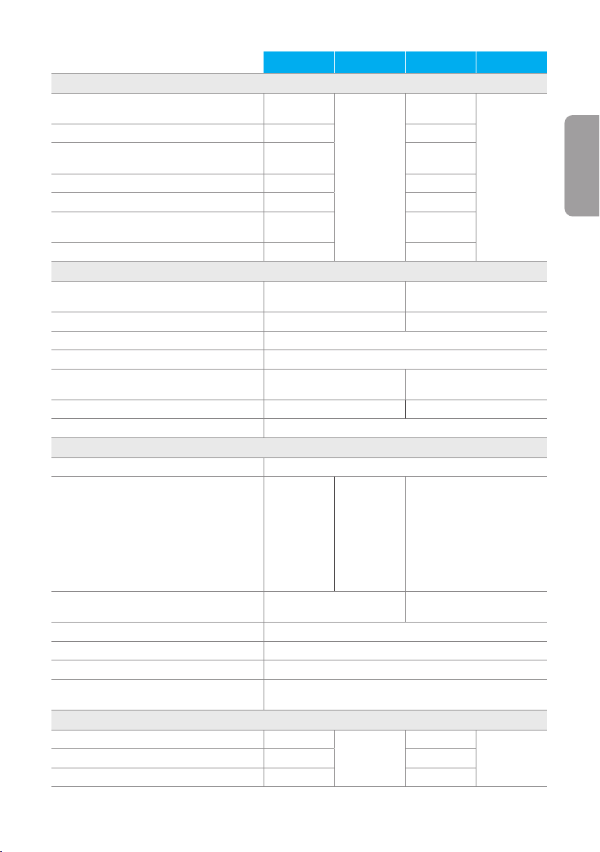
5 Basic Specifications ................................................................................ 6
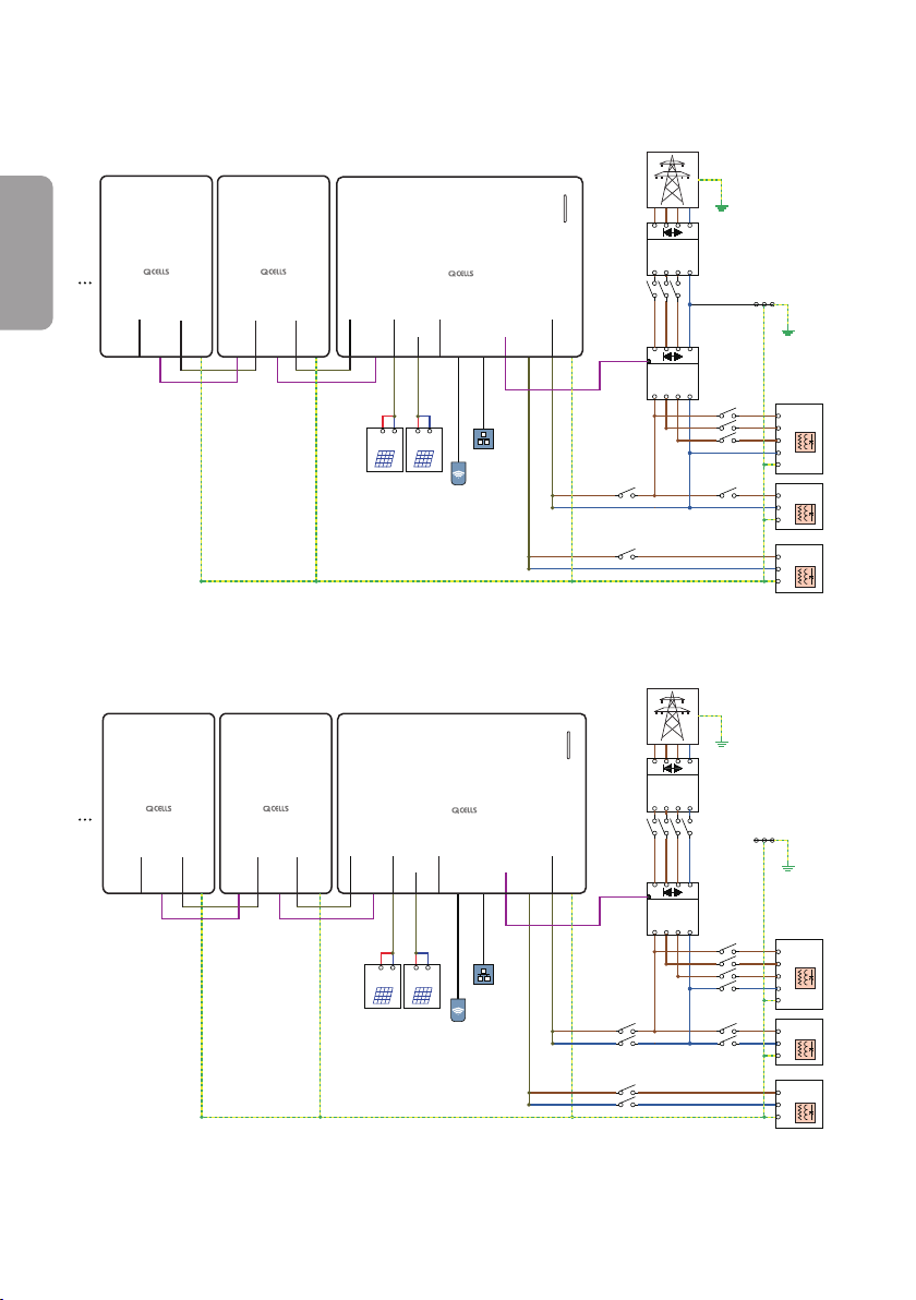
6 Wiring Scheme ......................................................................................... 9
7 Device Installation................................................................................... 11
7.1 Installation Requirements......................................................................................11
7.2 Wall Mount............................................................................................................... 12
7.3 Floor Mount (Option).............................................................................................13
8 Connecting the Cables ........................................................................15
8.1 Connectors Layout................................................................................................16
8.2 Opening the Covers .............................................................................................17
8.3 Wiring Cables Inside the Inverter......................................................................18
8.4 Assembling LAN & DRM Connector (only for Australia)........................... 19
8.5 Closing the Covers............................................................................................... 19
8.6 Connecting to PV ................................................................................................. 20
9 Energy Meter Wiring & Setting...........................................................21
9.1 EM24, Carlo Gavazzi (Three-Phase)................................................................21
9.2 EM24, Carlo Gavazzi (Single-Phase) .............................................................. 22
9.3 EM112, Carlo Gavazzi (Single-Phase) ............................................................ 23
9.4 CT Wiring................................................................................................................ 24
10 Connecting the Inverter to Battery Packs.....................................25
11 Power On ...............................................................................................26

English
12 LED Status ............................................................................................. 27
13 Connecting to the Internet ................................................................28
14 Setting the System...............................................................................28
14.1 Connecting to the system................................................................................ 28
14.2 Setting with the Q.OMMAND GO App....................................................... 29
15 Registering the Product...................................................................... 31
16 Submitting the Commissioning Report.......................................... 31
17 Power Off...............................................................................................32
Appendix A Commissioning Report.....................................................33
Appendix B Warranty................................................................................35

5
English
1 Downloading Manuals
For more details about how to install the product, visit the website
(https://www.q-cells.com) and download the installation manual.
GB DE AU FR
2 Symbols Used
This symbol indicates a hazardous situation which could result
in a light injury, if not avoided.
Note This indicates valuable tips for installation of the product.
3 Safety
• Q.HOME CORE H4/ A4 /H5 / A5 are hybrid PCS including an
inverter and batteries. The inverter weighs about 37.5 kg, and battery
pack weighs about 61.1 kg. Therefore, special care is required when
handling. At least two people have to carry and take it out.
• Do not operate with other components not approved by Q CELLS.
(Connecting other products to Q CELLS products may result in
abnormal operation.)
• All tasks regarding the PV module, inverter, and battery system
must be performed by certified personnel. Wear rubber gloves and
protective clothing while working.

6
English
• In case of short circuit, high-voltage components inside the inverter
may influence the product or other properties. Cover the product or
take other precautions to prevent metal objects from entering inside
during installation and wiring.
4 Requirements
• The internet connection is required to use all functions of
Q.HOME CORE H4/ A4 /H5 / A5.
• Installation protocol must be filled out and sent to E-Service. (This is
required only in Germany.)
5 Basic Specifications
H4 A4 H5 A5
GENERAL PRODUCT INFORMATION
Dimensions Inverter Module/Battery Module
(W × H × D) [mm] 460 × 700 × 221, 238 (From Wall)
Weight Inverter Module/Battery Module [kg] 37.5/61.1 33.9 / 61.1 37.5/61.1 33.9 /61.1
Operating Temperature Range [°C] Q.VOLT: −20 to +60 / Q.SAVE: −10 to +45
Relative Humidity [%] 4 to 100 (Condensing)
Protection Degree / Class IP65
Mounting Wall-Mounted or Floor-Mounted Options
Max. Operating Height without Power Loss [m]
2,000
Cooling Method Natural Air Cooling
Product Warranty/Performance Warranty 15 / 15 years
Noise Emissions ≤ 40 dB (A) @ 1 m
Over voltage Category OVC II (DC)/OVC III (AC)
Communications LAN, RS485, CAN, Wi-Fi(optional), LTE(optional)
Remote Monitoring Web, Mobile & App
Software Update Online update
Energy Management System Integrated
Country of Manufacturer Republic of Korea

7
English
H4 A4 H5 A5
PV DATA (DC)
Max. Input Usable Power [kWp] 8.0 (4.0 per
MPPT)
N/A
8.0 (4.0 per
MPPT)
N/A
Max. Input Voltage [VDC]600 600
Start Input Voltage/MPP Voltage Range [V] 120/90 to
550
120/90 to
550
Number of Independent MPPTs 2 2
Number of DC Input Pairs per MPPT 1 1
Max. Input Current per MPPT/Max. Short
Circuit Current per MPPT [A] 15 / 20 15/20
DC Connection Type MC4 MC4
GRID DATA (AC)
Max. Apparent Power/Rated Output Power
[kVA/kW] 5 (4.6 for DE)/5 (4.6 for DE) 5.0 /5.0
Nominal Voltage / Range [V] 230/184 to 264 230/180 to 260
Nominal Grid Frequency/Range [Hz] 50, 60 / −5 Hz to +5 Hz
Feed-in Phases/Connection Phases Single/Single
Nominal Current/Max. Current/Max. Over-
Current Protection [A]
21.7/25 / 30
(20/25 / 30 for DE) 21.7/25 / 30
Power Factor Range 0.95 lagging to 0.95 leading 0.8 lagging to 0.8 leading
Total Harmonic Distortion [%] ≤ 5
BACKUP POWER OUTPUT (ALTERNATING CURRENT)
Connection Phases Single
Rated Apparent Power / Rated Power (only
Battery) [kVA/ kW]
3.3 to 4.5/
3.3 to 4.5
@ 1 Battery
Pack,
5.0 /5.0 (4.6
for DE)
@ 2 Battery
Pack
3.3 to 4.5/
3.3 to 4.5
@ 1 Battery
Pack,
5.0 (4.6 for
DE)/5.0 (4.6
for DE)
@ 2 Battery
Pack
3.3 to 4.5/3.3 to 4.5@ 1
Battery Pack, 5.0 / 5.0@ 2
Battery Pack
Rated Apparent Power / Rated Power (with
PV) [kVA/kW]
5.0 (4.6 for DE)/
5.0 (4.6 for DE) (max) 5.0 /5.0 (max)
Rated Voltage [V] 230
Rated Frequency [Hz] 50, 60
Switch Over Time to Backup Power less than 0.1 seconds
Support by PV during Backup Power
Operation YES
EFFICIENCY
MPPT Efficiency [%] 99.9
N/A
99.9
N/AMax. Efficiency (PV to Grid) [%] 97 97
Max. Efficiency (PV to Battery) [%] 97.8 97.8

8
English
H4 A4 H5 A5
Max. Efficiency (Battery to Grid) [%] 96.3
BATTERY UNIT (DC)
Battery Technology Lithium-ion
Battery Energy [kWh] 6.8/13.7/20.5 (6.86 kWh/pack)
Battery Usable Energy [kWh] 6.51/13.03 / 19.55
Max. Charge Power [kW]
2.8 to 3.8
@ 1 Battery
Pack
5.0 @ 2
Battery Pack
2.8 to 3.8
@ 1 Battery
Pack
5.0 (4.6 for
DE) @ 2
Battery Pack
2.8 to 3.8 @ 1 Battery Pack
5.0 @ 2 Battery Pack
Max. Discharge Power [kW]
3.3 to 4.5 @ 1 Battery Pack
5.0 (4.6 for DE) @ 2 Battery
Pack
3.3 to 4.5 @ 1 Battery Pack
5.0 @ 2 Battery Pack
Converter Technology Non-isolated
Rated Battery Voltage / Battery Voltage
Range [VDC]202.8/168.0 to 228.2
Maximum Charge/ Discharge Current [A] 16.9/20
Depth of Discharge (DoD) [%] 95
CERTIFICATES AND APPROVALS
Inverter Model Name Q.VOLT
H4.6S
Q.VOLT
A4.6S Q.VOLT H5S Q.VOLT A5S
Battery Model Name Q.SAVE B6.8S
Certificates and Approvals
VDE-AR-N 4105:2018, CE,
IEC 62109-1, IEC62109-2,
IEC 62040-1, IEC 62619,
IEC 62477-1, EN61000-
6-2, EN61000-6-3,
IEC 60068.2-52, EN 60730-
1ANNEX.H
AS/NZS 4777.2:2020, CE,
IEC 62109-1, IEC62109-2,
IEC 62040-1, IEC 62619,
IEC 62477-1, EN61000-
6-2, EN61000-6-3,
IEC 60068.2-52, EN 60730-
1ANNEX.H

9
English
6 Wiring Scheme
Note: PV#1 and PV#2 are not available for A4 and A5 models.
TN-S Network System (Single-Phase)
Main Load
L
PE
N
PE
Circuit
Breaker
Critical Load
L
PE
N
Earth Bar
N
L
LN
kWh
(Utility Meter)
kWh
(ESS Meter)
Circuit
Breaker
Circuit
Breaker
Energy
Meter
(RS-485)
Circuit
Breaker
PE
PV#1
PV#2
LAN
DRM
RS-485
GRID
LOAD
PV1 Array PV2 Array
+ - + -
GRID
E
Q.SAVE #2 Q.SAVE #1
PE PE
BAT
IN BAT
IN
BAT
IN
BAT
OUT BAT
OUT
BMS
OUT
(CAN)
BMS
OUT
(CAN)
BMS
IN
(CAN)
BMS
IN
(CAN)
BMS
IN
(CAN) USB
Wi-Fi Dongle
Q.VOLT
TT Network System (Single-Phase)
Main Load
L
PE
N
PE
PV#1
PV#2
LAN
DRM
RS-485
GRID
LOAD
PV1 Array PV2 Array
+ - + -
Circuit
Breaker
Critical Load
L
PE
N
Circuit
Breaker
Circuit
Breaker
PE
Earth Bar
N
L
LN
kWh
(Utility Meter)
kWh
(ESS Meter)
Circuit
Breaker
Energy
Meter
(RS-485)
GRID
E
Q.SAVE #2 Q.SAVE #1
PE PE USB
Wi-Fi Dongle
Q.VOLT
BAT
IN
BAT
OUT
BMS
OUT
(CAN)
BMS
IN
(CAN)
BAT
IN
BAT
OUT
BMS
OUT
(CAN)
BMS
IN
(CAN)
BAT
IN
BMS
IN
(CAN)

10
English
TN-S Network System (Three-Phase)
PE
Circuit
Breaker
Circuit
Breaker
Main Load
Main Load
Critical Load
L
PE
N
PE
N
L
PE
N
L3
L2
L1
Earth Bar
L1 L2 L3 N
L1 L2 L3 N
kWh
(Utility Meter)
kWh
(ESS Meter)
Circuit
Breaker
Circuit
Breaker
Circuit
Breaker
Energy
Meter
(RS-485)
PEPE
PV#1
PV#2
LANUSB
DRM
RS-485
GRID
LOAD
Q.SAVE #2 Q.SAVE #1
PV1 Array PV2 Array
+ - + -
PE
GRID
E
Wi-Fi Dongle
Q.VOLT
BAT
IN
BMS
IN
(CAN)
BAT
IN BAT
IN
BAT
OUT BAT
OUT
BMS
OUT
(CAN)
BMS
OUT
(CAN)
BMS
IN
(CAN)
BMS
IN
(CAN)
TT Network System (Three-Phase)
Circuit
Breaker
PE
PV#1
PV#2
LAN
DRM
RS-485
GRID
LOAD
PV1 Array PV2 Array
+ - + -
PE
Circuit
Breaker
Circuit
Breaker
Main Load
Main Load
Critical Load
L
PE
N
PE
N
L
PE
N
L3
L2
L1
Earth Bar
L1 L2 L3 N
L1 L2 L3 N
kWh
(Utility Meter)
kWh
(ESS Meter)
Circuit
Breaker
Circuit
Breaker
Energy
Meter
(RS-485)
GRID
E
Q.SAVE #2 Q.SAVE #1
PE PE USB
Wi-Fi Dongle
Q.VOLT
BAT
IN BAT
IN
BAT
OUT BAT
OUT
BMS
OUT
(CAN)
BMS
OUT
(CAN)
BMS
IN
(CAN)
BMS
IN
(CAN)
BAT
IN
BMS
IN
(CAN)

11
English
7 Device Installation
7.1 Installation Requirements
Installation Environment
• For convenient maintenance, install the inverter at eye level.
• Secure the space for maintenance before installation.
• Although it supports the waterproof performance equivalent to the IP65
rating, install in a place not directly exposed to direct sunlight, rain, and
snow.
• While it can be installed by slanting it backward up to 5 degrees or
lower, do not install it tilted on the side. The wiring area should point
downward.
5˚
Installation Space
For efficient heat mission, a sufficient distance should be secured from
the surrounding objects and sufficient space for cable connection is
required.
300mm
300mm
300mm
300mm
600mm

12
English
Mounting Hole Dimensions
410 mm
320 mm
C
472 mm
Ø9
Ø9 9×15
7.2 Wall Mount
1Check the location of a hole of the bracket and drill a hole on the
wall.
• Mounting hole: Ø9
2Insert an anchor into the hole and fix the bracket with a bolt.
• Use the wall mount bolts included in the Q.VOLT package.
• At least 4 bolts are required to secure the bracket.

13
English
3Place the product on the bracket.
4Secure the bottom of the product to the bracket using the M6
bolts.
7.3 Floor Mount (Option)
1Assemble the stand legs.
• Bolt: M8 × 16 (included in the package)

14
English
2Fix the bracket to the stand legs.
• Bolt: M8 × 45
• Use the wall mount bolts included in the Q.VOLT package.
3Fix the stand on the floor.
• Nut: M12-16 (not included in the package)
4Place the product on the bracket, secure the product to the bracket
using the M6 bolt.
• See steps 3 and 4 in the "7.2 Wall Mount".

15
English
8 Connecting the Cables
• Before connecting electrical cables, make sure the AC circuit breaker,
PV switch, and DC switch are OFF.
AC Circuit Breaker: OFF
(in the junction box) PV Switch: OFF
(in the inverter)
DC Switch: OFF
(in the battery pack)
• Batteries can be replaced only by qualified personnel. If the battery
needs to be replaced, you must use a battery that meets the
manufacturer’s specifications.
• Make sure to match the polarity of the cables properly when
installing. Otherwise, it may cause electric shock or the product may
permanently be damaged. The damage from this is not covered by
the warranty.
• Before batteries are connected, all other connections should be done
and the battery interrupter must be off.

16
English
8.1 Connectors Layout
25 9
10
14 6 87
3
1 1
2 2
F
No. Connectors Wire Size
1Battery 6 mm2
2BMS Communication -
3PV A+ / PV A-
PV B+ / PV B- 4 - 6mm2
4Grid 6mm2
5Load 6mm2
6RS-485 -
7COM -
8COM (Spare) -
9LAN/DRM (RJ45) Category 5E
10 Wi-Fi/LTE -

17
English
8.2 Opening the Covers
Opening the Front Cover
To remove the front covers from the inverter and battery packs:
After pressing the latch at the bottom of the cover, raise the cover upward
to open it.
Opening the Wiring Cover
Remove the 9 bolts and open the inner cover.
• Bolt: M4

18
English
8.3 Wiring Cables Inside the Inverter
1
7
2 4 53 6
8
1: Load 5: Ext. CT
2: Grid 6: DRM
3: Ext. comm. 2 7: LAN
4: Ext. comm. 1 8: RS-485
Load and Grid wiring
PE N
LOAD
LPE N
GRID
L

19
English
8.4 Assembling LAN & DRM Connector (only for Australia)
Sealing Nut Ruber Seal
Push the LAN or DRM cable through the side of the ruber seal.
Cable OD range: 4 to 6 mm
Tighten the sealing nut.
(Tightening torque range:
5 to 15kgf·cm)
8.5 Closing the Covers
Note: Before close the covers, complete the energy meter and CT
installation. Fore details about installing energy meter and CT, see "9
Energy Meter Wiring & Setting" on page 21.
1Close the inner cover and tighten the 9 bolts.
• Bolt: M4
• Torque: 18kgf·cm/ 15.6lbf·in

20
English
2Close the outer cover.
a. Insert the cover to fit into the grooves on the main bady.
b. Slide it down while pressing the front side against the latch at the
bottom.
8.6 Connecting to PV
V
DC
AUTO
OFF
V
mV A
mA
Hz
OFF
OFF
V
mV A
mA
Hz
OFF
USB
• Before connecting or disconnecting the PV cables (Connectors: MC4
type), make sure the PV switch is turned off.
• Make sure the PV cables are connected with the correct polarity.
• Make sure the open circuit voltage does not exceed the inverter input
limit 600 V. Otherwise, the status of inverter is fault.
Note: PV connectors are not available for A4S and A5S models.
Other manuals for Q.HOME CORE H4
3
This manual suits for next models
3
Table of contents
Languages: