QEI 6QBI User manual

UG-1062 DIO-9100 USER’S GUIDE
UG-1091
6QBI QUICS Board
Interface
User’s Guide
April 2021

UG-1091 6QBI User’s Guide
Copyright © 2021 by QEI, LLC
UG-1091 6QBI QUICS Board Interface User’s Guide
ALL RIGHTS RESERVED
NOTICE
The information in this document has been carefully checked and is believed to be
accurate. However, no responsibility is assumed or implied for inaccuracies.
Furthermore, QEI, LLC reserves the right to make changes to any products herein
described to improve reliability, function or design. QEI, LLC does not assume
liability arising out of the application or use of any product or circuit described herein;
neither does it convey any license under its patent rights nor the rights of others.
This manual and all data contained constitutes proprietary information of QEI and
shall not be reproduced, copied or disclosed to others, or used as the basis for
manufacture without written consent of QEI, LLC.
Springfield, NJ 07081
Phone: (973) 379-7400
Fax: (973) 379-2138
Web Site: www.qeiinc.com

UG-1091 6QBI User’s Guide
6QBI User’s Guide Revisions
•
i
Revisions
Revision
Description
Date
A
Initial Release
Dec 6th 2018
B
Changes due to firmware
revisions.
Dec 19th 2018
C
Changes due to firmware
revisions.
Jan 18th 2019
D
Changes due to firmware
revisions.
Jun 19th 2019
E
Changes due to firmware
revisions.
Aug 29th 2019
F
Changed Calibration Mode.
Oct 2nd 2019
G
Added 6PIB1 functionality.
April 26th 2021

UG-1091 6QBI User’s Guide
6QBI User’s Guide Contents
•
i
Contents
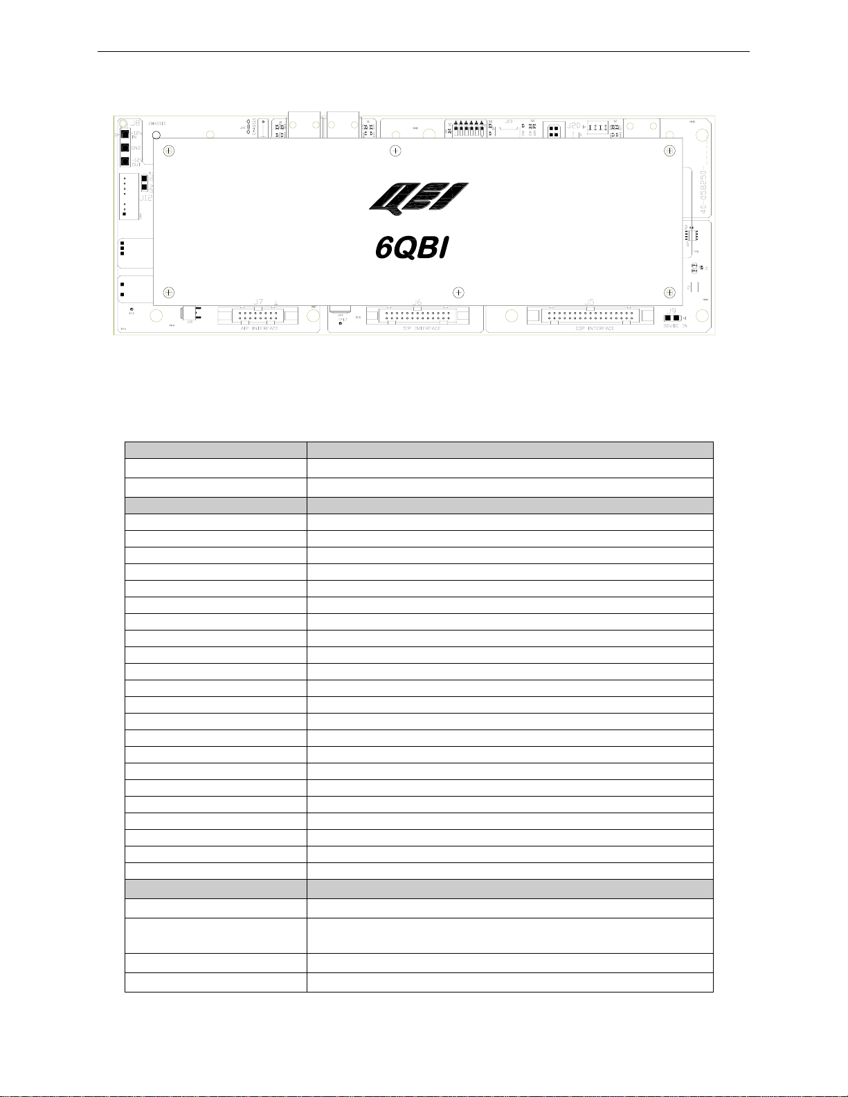
1Description................................................................................1
2Specifications...........................................................................2
3Input Power Connections ........................................................4
46SIP1 Status Panel Interface ...................................................5
4.1 General................................................................................5
4.2 6SIP1 Status Connector J6 Pinout.......................................6
56COP1 Control Panel Interface ...............................................7
5.1 General................................................................................7
5.2 6COP1 Control Connector (J5) Pinout.................................8
66AIP1 Analog Panel Interface..................................................9
6.1 General................................................................................9
6.2 6AIP1 Analog Connector (J7) Pinout .................................10
7Communications Ports..........................................................11
7.1 General..............................................................................11
7.2 RS-422 Ports (J14 Port 1, J13 Port 2)................................11
7.3 Serial Fiber Port (Optional) ................................................12
7.4 USB Maintenance Port (J5) ...............................................14
8Dip Switches...........................................................................15
8.1 Option DIP Switches (SW1)...............................................15
8.2 Watchdog Disable Switch (SW1 Position 6).......................16
9LED Indications ......................................................................17
10 Earth Grounding.....................................................................18
10.1 Earth Grounding Method....................................................18
11 Mechanical..............................................................................18
12 Installation ..............................................................................19
12.1 General..............................................................................19
12.2 Typical Installation Examples.............................................19
13 Ordering Information..............................................................21
14 Software ..................................................................................22
14.1 General..............................................................................22
15 Test Panel (Maintenance) ......................................................23
15.1 Introduction........................................................................23
15.2 Requirements....................................................................23
15.3 Functional Test Capability..................................................24

UG-1091 6QBI User’s Guide
15.3.1 Analog Monitoring...............................................24
15.3.2 Status Monitoring................................................24
15.3.3 Accumulator Monitoring ......................................24
15.3.4 Control Operation................................................24
15.4 Help for Test Panel Commands.........................................24
15.5 Reading Analog Values (RA).............................................26
15.6 Reading Status Values (RS)..............................................26
15.7 Reading Accumulator Values (RC) ....................................26
15.8 Relay Control.....................................................................27
15.8.1 On Relay Operation: CN <point> <dwell> ...........27
15.8.2 Off Relay Operation: CF <point> <dwell>............27
15.9 Communication Checks.....................................................28
15.9.1 PRX Command...................................................28
15.10 Displaying the Software Version (VER)..........................29
15.11 PRCAL...........................................................................29

UG-1091 6QBI User’s Guide
Copyright © 2021 QEI Description
•
1
1 Description
The 6QBI QUICS Board Interface is a microprocessor-based system that is part of
the QEI family of Distribution Automation Products. It communicates with the QEI
ePAQ-9410/942x (or MicroPAQ-940P) and operates QEI Legacy QUICS-4000 6AIP1
(Analog), 6SIP1 (Status), 6COP1 (Control), and 6IOP1 I/O panels. When combined
with a 6PIB1 and the appropriate firmware, it can also operate with older QUICS-
3000 I/O panels (6AMP, 6SMP and 6ROP)
The 6QBI allows the user to replace an existing QEI 6CPPX Central Processing
Panel (6CPP2/3/4/6) in a legacy RTU system and upgrade it to an ePAQ-9410/942x
or MicroPAQ-940P, to benefit from QEI’s latest RTU technologies, without the need
for changing out the legacy panels.
Like the 6CPPX interface it replaces, the 6QBI supports all QUICS-4000 panel
models as well as the same number of each I/O panel per RTU, along with all the
same functionality for the panels. With the QUICS-3000 series panels the number of
status points is limited to 320. For analogs and control points, the 6QBI supports up
to the maximum allowable via a 6PIB1.
When paired with the MicroPAQ-940P, the 6QBI can be retrofit to replace a 6CPPX
within the existing space in the RTU cabinet.
The 6QBI includes two RS-422 communications ports for communication with an
ePAQ-9410/2x or MicroPAQ-940P. These two ports may also be used in redundant
configurations. A USB port is available for local test and diagnostics via any PC
terminal software. Included LED indicators show RS-422 communications traffic (i.e.,
TX, RX) and on-board diagnostics. A serial fiber port is also an available option and
a microSD card slot is included for firmware updates.
Requiring only the configuration of the MicroPAQ-940P or ePAQ-9410/942x local I/O
clients, the 6QBI is designed to allow these multifunction gateway RTU models to
transparently interface with QUICS-3000 or QUICS-4000 I/O Panels (6PIB1
Required).

6QBI User’s Guide UG-1091
2
•
Specifications Copyright © 2021 QEI
2 Specifications
General
Description
Main Microcontroller
Microchip 16-Bit 128KB Flash 96 MHz
Communications Ports
Port 1:
Interface
Isolated RS-422 (Main Port #1)
Bit Rate
115.2Kbps
Protocol
Asynchronous Byte Oriented
Connector
RJ45 (J13)
Port 2:
Interface
Isolated RS-422 (Main Port #2)
Protocol
Asynchronous Byte Oriented
Bit Rate
115.2Kbps
Connector
RJ45 (J14)
Port 3:
Interface
Serial Fiber (Multimode)
Protocol
Asynchronous Byte Oriented
Bit Rate
115.2Kbps
Connector
ST Connectors (TX/RX)
Port 4:
Interface
USB 2.0 (Maintenance Port)
Connector
USB Type B (J20)
Control Point Interface
(J5)
Panel Type
6COP1 or 6PIB1
Addressability
Sixteen 6COP1 or 6ROP panels x 8 control points/panel = 128
points.
Drive Voltage
30Vdc, nominal
Control Pulse Duration
250 msec. (default)
RS-422 OPTION SW. MAINT.
6AIP1 6SIP1 6COP1

UG-1091 6QBI User’s Guide
Copyright © 2021 QEI Specifications
•
3
Current
100 mA max.
Safety
One relay operation at a time.
Connector
34-pin IDC header.
Status Point Interface
(J6)
Panel type
6SIP1 or 6PIB1
Bit Width
16 bits
Addressability
Sixteen 6SIP1 Panels x 16 pts/panel = 256 points or Twenty
6SMP Panels x 16 pts/panel = 320 points
Connector
26-pin IDC header.
Analog Point Interface
(J7)
Panel type
6AIP1 or 6PIB1
Addressability
Eight 6AIP1 or 6AMP Panels x 16 pts/panel = 128 Analog
Points
Input Voltage
-5Vdc to +5Vdc
Reference Voltage
+2.5 and -2.5 Vdc
A/D Converter:
Number of Bits
12bits (11 bits + sign bit)
Accuracy
+/- 1 Bit
Conversion rate
50 conversions per second minimum
CMRR
70 dB min. for power line fundamental (ref: Earth gnd).
Normal Rejection
70 db for power line fundamental.
Isolation
1 kVdc analog common to logic common
Connector
16-Pin IDC Header
Power Input
Voltage
12Vdc nominal
Current
3VA nominal (200mA@12Vdc)
Connector
3-pin socket J8 (Pin 1 = +12Vdc Pin 2 = DC Common)
30Vdc
2-pin socket J9, (Pin 1 = +30Vdc, Pin 2 = NC)
Power Output
12VDdc Aux
2-pin socket J12 (Pin 1 = +12Vdc, Pin 2 = DC Common)
-12Vdc
3-pin socket J8, (Pin 3 = -12Vdc, Pin 2 = DC Common)
Environment
Temperature
-40 to +85oC
Humidity
5 to 95% @ +70oC, non-condensing
Tests
IEEE 1613-2009 various tests.
Physical
Mounting Dimensions
11.675” L x 4.25” W x 1.5” D
Weight
0.5 lb.

6QBI User’s Guide UG-1091
4
•
Input Power Connections Copyright © 2021 QEI
3 Input Power Connections
The 6QBI accepts +12Vdc input nominal, maximum +16Vdc.
Input power connections are made at 3-pin connector J8.
J8 PIN#
Name
Description
1
+DC Input
Connect a +12Vdc
Power Supply here.
2
Common
Power supply
common connection
here.
3
-DC Output
-12Vdc @200mA
output connection
here.
RS-422 OPTION SW. MAINT.
6AIP1 6SIP1 6COP1
1 = +12VDC IN
2 = COMMON
3 = -12VDC OUT

UG-1091 6QBI User’s Guide
Copyright © 2021 QEI 6SIP1 Status Panel Interface
•
5
4 6SIP1 Status Panel Interface
4.1 General
The Status Panel Interface (J6) provides the means for the system to sample digital
input data points. These digital points can be configured in various ways, for
example:
•Individual Status Points (on/off indications)
•Accumulators, where the pulse count reflects a value.
Note that the SIP or SMP configuration profile is that of a Status Input Module (SIM).
Each group of 4 6SIP1 or 6SMP boards constitute one SIM module. Each group of
64 Status Points are assigned a unique address in sequence 0 thru 3. The Status
Panel Interface is capable of monitoring up to 16 individual Status Input Panels
(6SIP1) each containing 16 inputs, for a total of 256 individual digital input points.
When paired with a 6PIB1, the Status Panel Interface can monitor 20 Status
Multiplexer Panels (6SMP) containing 16 inputs each, for a total of 320 digital input
points. Some communication protocols, may limit the number of input points defined
as status points to a lesser number of points.
The Status Panel Interface, under program control, reads the state (0 or 1 value) of
the digital points in the selected status panels. This value is stored in RAM for
further processing and subsequent transmission to the "client".
A 26-pin IDC header, J6, is used for the connections to the 6SIP1 or 6PIB1 panel
through a 26-conductor ribbon cable. Signals in this connector include:
•5 panel select lines
•16 data bit lines
•1 LATCH-EN line (turns on the V1 LED on the 6SIP1 panel)
•1 SIP-ACK line (Status Panel Acknowledge)
•1 +12 VDC power line
•2 power common lines

6QBI User’s Guide UG-1091
6
•
6SIP1 Status Panel Interface Copyright © 2021 QEI
4.2 6SIP1 Status Connector J6 Pinout
RS-422
SERIAL
FIBER OPTION SW. MAINT.
6AIP1 6SIP1 6COP1
PIN 1
PIN 2
PIN 25
PIN 26
J6 PIN#
Name
Description
1
+12V
+12V Power out to 6SIP1 Panels.
2
SIP ACK
6SIP1 Panel Acknowledge Input.
3
COM
Power output common.
4
COM
Power output common.
5
PSEL BIT3
Panel Select Bit 3.
6
PSEL BIT1
Panel Select Bit 1.
7
PSEL BIT4
Panel Select Bit 4.
8
LATCH EN
Latch Delay Pulse.
9
PSEL BIT0
Panel Select Bit 0.
10
PSEL BIT2
Panel Select Bit 2.
11 thru 26
Status Word
Sixteen Bit Status Word from 6SIP1.

UG-1091 6QBI User’s Guide
Copyright © 2021 QEI 6COP1 Control Panel Interface
•
7
5 6COP1 Control Panel Interface
5.1 General
The Control Panel Interface (J5) provides the means for the system to momentarily
energize external relays (control output points) in response to control commands
received from the "client", or locally generated from internal processes.
The Control Panel Interface has the capability of controlling up to 256 momentary
relays, or 128 control point outputs.
Each control output point consists of one pair of complementary command functions,
such as OPEN/CLOSE, SET/RESET, etc. Each control output point is normally
equipped with an external pair of momentary relays, or a single latching relay. These
external relays are arranged, or grouped, in external control point output panels.
There are several control point output panel arrangements with the 6COP1 or 6ROP,
the most commonly used are groupings of eight control output points, however some
may have only four control output points or less.
The Control Panel Interface executes a command by selecting a single external
relay, then energizing its coil for a pre-defined period of time. To do this, the Control
Panel Interface provides 16 current source lines and 16 current sink lines. The
current source lines (8 trip and 8 close) act as a relay select, while the current sink
lines act as a panel select (group of 8 control output points). Together, they
complete a current loop that energizes the selected relay.
The Control Panel Interface includes circuitry to ensure that only one output relay is
energized at a time. If more than one relay is being energized, because of
component failure, a selected-row/column detector aborts the command.
An external 30 VDC power source is required for relay operation. A 2-pin miniature
MOLEX connector, J9, is provided for this input.
A 34-pin IDC header, J5, is used for the connections to the control point output
panels (6COP1 or 6ROP) through a 34-conductor ribbon cable. Signals in this
connector include:
•16 column lines (panel selects)
•8 trip lines (relay selects)
•8 close line (relay selects)

6QBI User’s Guide UG-1091
8
•
6COP1 Control Panel Interface Copyright © 2021 QEI
5.2 6COP1 Control Connector (J5) Pinout
RS-422
SERIAL
FIBER OPTION SW. MAINT.
6AIP1 6SIP1 6COP1
PIN 1
PIN 2
PIN 33
PIN 34
J5 PIN#
Name
Description
1
NC
No Connect.
2
NC
No Connect.
3 thru 10
TRIP 0-7
Trip Row Lines 0 thru 7.
11 thru 18
CLOSE 0-7
Close Row Lines 0 thru 7.
19 thru 34
COLUMN 0-15
Column Lines 0 thru 15.

UG-1091 6QBI User’s Guide
Copyright © 2021 QEI 6AIP1 Analog Panel Interface
•
9
6 6AIP1 Analog Panel Interface
6.1 General
The Analog Panel Interface (J7) samples differential analog input signals that are
wired to the 6AIP1 or 6AMP Analog Input Panels, at any given time one of up to
eight 6AIP1s and one of the sixteen input points in each pane is selected. The
Analog Panel Interface continuously samples in this manner for a total of 128 analog
inputs. The Analog Panel Interface also includes two fixed reference points (–2.5
and +2.5 VDC). If these two reference points are used, they must be included as
two of the 128 analog points.
The selected analog input, in the range of 0 to +5 VDC, is digitized by the A/D
converter into a 12-bit signed value (11-bit plus sign). This value is stored in RAM
for further processing and subsequent transmission to the "client".
Unlike the other panel interfaces, where the isolation is done at the panels
themselves, the Analog Panel Interface has its own isolation on board. A DC/DC
converter provides the necessary power supply and isolation for the analog input
panels, while opto-isolators are used to provide isolation for the logic signals.
A 16-pin IDC header, J7, is used for the connections to the analog input panels
(6AIP1 or 6AMP) through a 16-conductor ribbon cable. Signals in this connector
include:
•3 panel select lines
•4 point select lines
•1 enable line
•2 15 VDC isolated power lines
•3 common (analog ground)
•2 analog signal lines
•1 acknowledge line
Additional scaling and measurement ratios are accomplished via software
configuration.

6QBI User’s Guide UG-1091
10
•
6AIP1 Analog Panel Interface Copyright © 2021 QEI
6.2 6AIP1 Analog Connector (J7) Pinout
RS-422
SERIAL
FIBER OPTION SW. MAINT.
6AIP1 6SIP1 6COP1
PIN 1
PIN 2
PIN 15
PIN 16
J7 PIN#
Name
Description
1
+ANA IN
+ Analog Input
2
+A15
6AIP1 Power +15Vdc.
3,5,7
PNL SEL X
Power Common
4
-A15
6AIP1 Power -15Vdc.
6 &8
ACOM
Power Common
7,9,11,13
PT SEL X
Panel Point Select & Ack.
14
ACOM
6AIP1 Signal Common.
15
-ANA IN
- Analog Input.
16
+ANA IN
+ Analog Input.

UG-1091 6QBI User’s Guide
Copyright © 2021 QEI Communications Ports
•
11
7 Communications Ports
7.1 General
The 6QBI communicates via RS-422 port with a MicroPAQ-940P or ePAQ-9410 /
ePAQ-942x, via the expansion port on either RTU. There are two RS-422 ports on
the 6QBI. These ports may be used one at a time, or simultaneously for redundant
communications with the 6QBI by two RTUs. Both of the 6QBI RS-422 ports are
isolated (shared isolation) and transient protected.
The 6QBI also includes an available optional serial fiber port for use with the ePAQ-
9410 or ePAQ-942x. Also included is a USB Maintenance Port for field testing and
troubleshooting.
7.2 RS-422 Ports (J14 Port 1, J13 Port 2)
Two isolated RS-422 communication ports. Connections are via 8-pin RJ45
connectors. Baud rate is fixed at 115.2 kbps for compatibility with the ePAQ-9410,
ePAQ-942x, and MicroPAQ-940P RS-422 expansion ports.
Connection between the 6QBI and ePAQ/MicroPAQ ports is via any one-to-one
RJ45 cable.
RS-422
SERIAL
FIBER OPTION SW. MAINT.
6AIP1 6SIP1 6COP1
PIN 1

6QBI User’s Guide UG-1091
12
•
Communications Ports Copyright © 2021 QEI
RS-422 Port Pinout
Each RS-422 Port (J13, J14) includes a 120 ohm termination resistor (if needed)
across each RX input pair. The termination resistors are enabled via a 2-pin plug-in
jumper for each port. Jumper plug J15 enables the termination for Port 1 (J14), and
jumper plug J16 enables it for Port 2 (J13).
7.3 Serial Fiber Port (Optional)
The optional Serial Fiber Port (TX/RX) allows for 6QBI communications with the
ePAQ-9410 or ePAQ-942x via serial fiber.
Connections are made via ST fiber connectors using multimode POF fiber. It may be
necessary to remove the 6QBI front cover to reach the fiber connections.
Designation on 6QBI: TX →and RX
Connector Type: Separate Fiber optic Receiver and Transmitter with ST
bayonet type connectors (quarter turn locking).
Receiver: Avago HFBR-2412Z.
Transmitter: Avago HFBR-1414Z.
Wavelength: 820 nm
Data Rate: 115.2kbps fixed
J13, J14 PIN#
Name
Description
1
GND
Common
2
GND
Common
3
RS-422
RX+
4
RS-422
TX+
5
RS-422
TX-
6
RS-422
RX-
7
NC
Not Connected
8
NC
Not Connected

UG-1091 6QBI User’s Guide
Copyright © 2021 QEI Communications Ports
•
13
RS-422 OPTION SW. MAINT.
6AIP1 6SIP1 6COP1
SERIAL
FIBER

6QBI User’s Guide UG-1091
14
•
Communications Ports Copyright © 2021 QEI
7.4 USB Maintenance Port (J5)
The maintenance port (J5) is designed for direct connection to a PC. This port may
be used for local test functions, such as viewing status and analogs, etc. See the
appendix for available test panel functions.
The port uses a USB type B connection. Typical connection to a PC is through any
USB-B to USB-A cable (not supplied). This port is compatible with terminal programs
such as TeraTerm, PuTTY, and HyperTerm and may require installation of the 6QBI
USB driver depending on Windows version. Any baud rate will work with the 6QBI.
RS-422 OPTION SW. MAINT.
6AIP1 6SIP1 6COP1
MAINT.

UG-1091 6QBI User’s Guide
Copyright © 2021 QEI Dip Switches
•
15
8 Dip Switches
8.1 Option DIP Switches (SW1)
SW1 is a 4-position dip switch bank. During normal RS-422 communications, all four
DIP switch positions are OFF (UP). The function of each switch is as follows:
DIP Switch #
Function
1
On = J13 and J14 RS485 Operational
2
On = Fiber port and J13 Operational
3
On = J13 to Fiber repeater
4
Not Used
5
Not Used
6
On = Watch Dog OFF, LED D1 is illuminated
RS-422 OPTION SW. MAINT.
6AIP1 6SIP1 6COP1
Table of contents
Other QEI Recording Equipment manuals