QL 140E-1 Series User manual

Quincy Lab, Inc. 1925 N. Leamington Ave. Chicago, Illinois 60639 1-800-482-HEAT (4328)
*
*
*
*
Quincy Lab, Inc.
View Setpoint
(PRESS)
Increase Setpoint
Decrease Setpoint
(3 sec.) Enter/Exit Menu Levels
Model 12-140E ncubator
POWER
DIGITALMICROPROCESSOR
140 SERIES
Switch
opening
Quincy Lab, Inc.
PAGE 1
Issue Rev C 0310
Copyright Quincy Lab Inc. 2009
Model Series 140E-1 & 180E-1 (230 V )
General Purpose Incubators
OPERATING MANUAL
I
Model 10-180E-1
DIGITALMICROPROCESSOR
*
*
*
Quincy Lab, Inc.
ViewSetpoint
(PRESS)
Increase Setpoint
Decrease Setpoint
(3 sec.) Enter/Exit Menu Levels
Model 10-180E ncubator
I
POWER
Switch
opening
140 SERIES
Model 12-140E-1
Interior Dimensions
INCHES W x H x D
(CM) W x H x D
Exterior Dimensions
INCHES W x H x D
(CM) W x H x D
12x10x10 18x16x12 18x16x1212x10x10
13x15x11 19x21x13 13x15x11 19x21x11
Standard Electrical: 230 volts, 50/60 Hz
31x25x25 46x41x30 46x41x3031x25x25
33x38x28 48x53x33 33x38x28 48x53x33
SPECIFICATIONS MODEL
10-140E-1 MODEL
12-140E-1 MODEL
10-180E-1 MODEL
12-180E-1
Common Unit Construction
Exterior: Powder-Coated Steel Interior: Aluminum
Insulation: Fiberglass Door: 140E-1:Acrylic, 180E-1:Steel Insulated
Thermo-control: PID Microprocessor Heater: Resistive-Tubular Incoloy
WATTS 120 235 270 385
Cubic Foot Capacity
.7 ft32.0 ft3.7 ft32.0 ft3
Common Unit Specifications
Operating Environment: Indoor use, altitude to 6,500 ft. (2,000m) Installation Category II,
Pollution Degree 2, ambient temperature 10oC/50oF to 35oC/95oF,
80% RH maximum.
Storage Temperature: -10oC/14oF to 70oC/158oF, 70% RH maximum.
Approvals: Underwriter's Laboratory Listed, Laboratory Equipment, C/UL
United States/Canadian. E212550 (115VAC models only)
Compliance: UL Standard 61010-1, IEC 61010-1, 2nd Edition.
Weight (lbs) 19 lbs 33 lbs 19 lbs 33 lbs
Temperature Range
Ambient + 2
o
C to 62
o
C
Ambient + 3
o
C to 94
o
C

PAGE 2
AB
CD
FIG. 1
*
*
*
*
View Setpoint in oC / oF units
(PRESS)
Increase Setpoint
Decrease Setpoint
(3 sec.) Enter/Exit Menu Levels
FIG. 2
Set-up & Installation
Read Operating Instructions Thoroughly Prior to Operation
Safety Precautions
Read Operating Instructions thoroughly prior to operation. Use only a grounded outlet that is rated for your
model's electrical requirement. Do not modify the oven or factory control settings to operate the oven above the
stated maximum operating temperature. Exterior surfaces on 180E-1 models may become hot to the touch when
operating at higher set temperatures. Conduct periodic maintenance as required.
General Operation
*
Chamber Loading
Position unit in its ultimate operating location. Keep a minimum of
3" of airspace around the unit and a minimum of 6" above the unit.
The port hole at the top of the unit will expel a small amount of
warm air through natural convection. This port can also be used as
an access way for external temperature measurement of a solution
for example.
Install adjustable shelf by placing the ends of the wire shelf bracket
into the corresponding holes located on the inner sides of the oven
at the desired height. Push the ends of the bracket into the holes
until the first bends in the bracket are against the wall, then rotate
the bracket down. Place the shelf on the brackets. (FIG 1)
Plug the unit into a grounded outlet for your unit's rated voltage.
The unit is ready for your immediate use. All control parameters,
calibration and tuning has been done at the factory, no adjustments
are necessary.
Push the illuminated power button. All LED's on the temperature
control will light up for 5 seconds until the current or actual chamber
temperature is displayed.
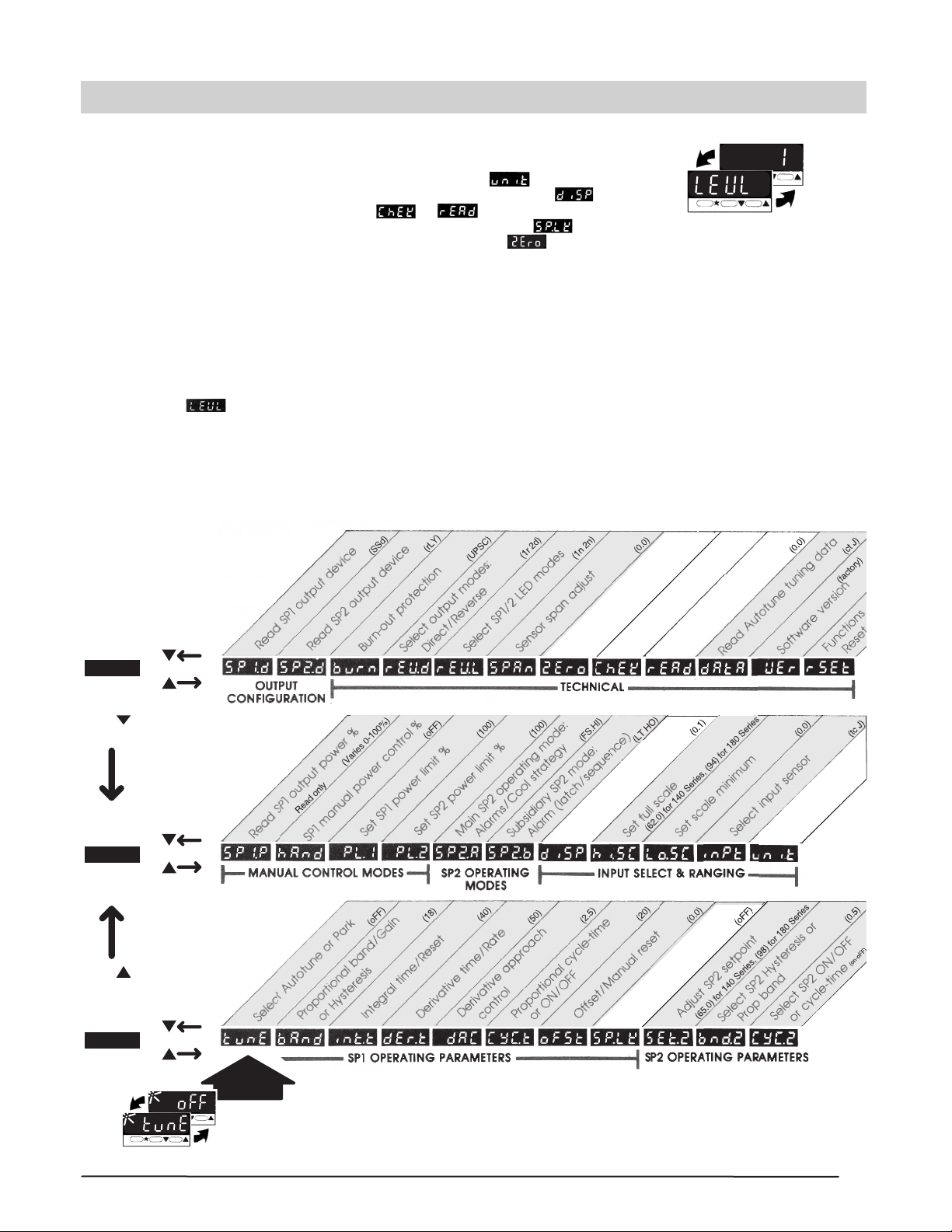
To view the set temperature press the star " " key. To change the
set temperature, hold the star key together with the up (raise temp)
or down (lower temp) arrow key until the desired temperature is
indicated on the LED display. (FIG 2) The temperature control is
set at the factory to read in 1/10 degree C (centigrade) units. To
change temperature units or display resolution see: Menu Level
Functions (page 3).
Once the unit reaches the set temperature, allow the unit to cycle
for 20 minutes at set point before temperature becomes fully stable.
NOTE: Upon each initial powering-up, the control may typically overshoot the set temp by 2 to 4 degrees,
especially if the temperature set point is close to the operating ambient temperature. After equilibrium is achieved
the control will hold set temperature within 1 unit degree.
Article processing times and temperature uniformity are largely dependent on load density and positioning. Load
the incubator so that the air circulation within the incubator is not impaired. Here are some general guidelines:
Leave a space between articles on a shelf. Stagger articles from those on lower shelves.
Avoid placing articles or media against or within an inch of the walls, especially on the lower shelf. Heated air from
the lower plenum openings, designed to travel up the side walls, can have a slightly elevated temperature from set
point and the rest of the chamber.
Use of large solid trays or foil on shelves limits heat to any articles placed on shelves above.
Avoid extremely large (in quantity or size), or high-density loads. This will show by non-uniform processing and
long or impossible "heat-through" times. To help determine a load's suitability, use the set-point recovery time (the
time it takes for the temperature to recover to the original set temperature once the load is placed), as a guide. To
reduce recovery time, reduce load proportionally. When possible, measure large loads or solution temperatures
directly with an ancillary thermometer or probe. Probes can be inserted at the top port.
For best processing performance for a single item, adjust one shelf so that the article is centered in the incubator
chamber.

LEVEL 3
*
(PRESS)
(PRESS)
Temperature Tracking Monitor
ON / OFF
Control Calibration Adjust
Set Temperature Lock
OFF/ON
(oFF)
(-10 to +10)
)
Select Display Resolution
1 / 0.1
Select oC / oF
NONE,oC, oF, Bar, PSi, Ph
Read Tracking Monitor Results
VAR / HI / LOW
*
(PRESS)
(PRESS)
(PRESS)
LEVEL 2
LEVEL 1
MENU ENTRY
POINT
(C)
Functions Menu
Guide
IMPORTANT NOTE: The grey-shaded control functions within the menu levels are factory
tuned and set for the optimum performance and the safe operation for your model
incubator. Care should be taken when navigating or changing user applicable settings
so as not to alter these factory settings. Factory settings for each function are listed within
the parentheses "( )" on each function tab above. Use as a trouble-shooting reference.
PAGE 3
Access the menu levels for the following functions: (user applicable functions and
their menu locations are high-lighted in white in the Functions Menu Guide below).
~ Change control to read in C or F temperature units.( in level 2)
~ Change to whole degree or 1/10th degree display resolution.( in level 2)
~ Run or Read temperature tracking.( or in level 3)
~ Lock Temperature setting against inadvertent adjustment.( in level 1)
~ Calibrate control temperature to an external standard.( in level 3)
To access the control's function menu:
Press and hold both arrow keys for 3 seconds then release when the "tune" function prompt is displayed from
within LEVEL 1 (see "menu entry point" at the bottom of the Menu Guide below). When in the function menu
the LED display will alternate the function prompt with the function setting when keys are released. (FIG 3)
To navigate within the functions menu:
Use up and down arrow keys individually to move "right" or "left" within a level. Press and hold the star key
and then the up or down arrow keys to move "up" or "down" respectively through levels 1, 2 and 3 (Note: you
must be at prompt to move up or down levels).
To change a function setting:
Once at the desired level function prompt, press and hold the star key and press the up or down key to select
or change the function setting. Release star key to set the function. Press the up and down keys together to
return to temperature display or the control will auto-return in 60 seconds.
FIG. 3
FUNCTION PROMPT
FUNCTION SETTING
Alternating
Display
Control Menu Functions

*
Release or Press/Hold
Displays variance
(0.6o)*
Press/Hold
Press once
Displays maximum *
Press/Hold
Press once more
Displays minimum
Thermocouple burnout
Check sensor/wiring Non-volatile memory error
De-power briefly
Replace unit if it persists
(Press together to
clear alarm condition)
Alarm condition: Temp exceeded maximum
operating temp (62 C). Heater shutdown
until manually reset. Typically indicates
relay or temperature control failure.
Replace relay or temp control if persists.
PRESS
To clean interior and exterior surfaces, use a damp cloth with or without an all-purpose cleaner. The acrylic door
should only be cleaned using a lint-free cloth, with or without water. Paper towels can mar the surface of the
acrylic door. Use of any commercial cleansers on the acrylic door will cause crazing and cracking of the surface of
the acrylic over time. Periodically, check the accuracy of the control's temperature display against a known
accurate or calibrated device. This should be done with an empty chamber after the set temperature becomes
steady (typically after 45 to 60 minutes). Calibrate the control in the control's functions menu, level 3 (see page 3).
This feature monitors the stability of the control during for any given length process. It will record and display: 1.
The total variation or spread between high and low, 2. The absolute or maximum high and 3. The absolute or
minimum low.
To start the tracking feature navigate to "CheK" prompt in menu level 3. Hold star key then up arrow key to select
ON. Return to temp display or control will auto-return in 60 seconds. The control will track the temperature
variation until "CheK" is turned off. Recorded readings are retained until next "CheK" ON.
You can view readings at any time during or after tracking feature has been turned off. But de-powering the unit
will reset "CheK" to OFF and "rEAd" to zero. To view readings navigate to "rEAd" prompt in menu level 3. Then:
TIP: To avoid erroneous tracking data from run-up temperatures or door openings, start the Tracking feature after
articles have been placed and temperature steadies at set point.
PAGE 4
Control prompts will only display when a fault or alarm condition exists.
Temperature Tracking Feature
Control Self Diagnostics
Maintenance / Control Calibration
Tech Support
Limited Warranty
Quincy Lab, Inc. warrants to the original purchaser that this product will be free from
defects in material and workmanship under normal use throughout the warranty period.
The standard warranty period for this instrument is 18 months from date of shipment.
The instrument warranty is supplemented with a 3-year warranty on the heating
element. Please refer to your invoice or shipping documents to determine the effective
warranty period. This warranty covers parts and labor (labor at factory only), and
shipping costs for replacement parts.
If you have any questions or need technical assistance, please contact Quincy Lab customer support at
Voice: 800-482-HEAT (4328) 1925 North Leamington Avenue
Fax: 773-622-2282 Chicago, Illinois 60639
Example for 140E-1 Series
This manual suits for next models
5
Table of contents
Other QL Accessories manuals
Popular Accessories manuals by other brands

Siko
Siko MSK320R Installation

Ubiquiti
Ubiquiti mFi-DS quick start guide

Lifetime
Lifetime QUICK ADJUST 90023 Assembly instructions

ETC
ETC Aero SimpleTap Occupancy Sensor installation guide

Rockler
Rockler Titanium Gold Pioneer instructions

PCB Piezotronics
PCB Piezotronics ICP 208A24 Installation and operating manual