CAI-QMICR-01: QMicro Receptacle Connector Customer Assembly Instructions
Page 3 of 13
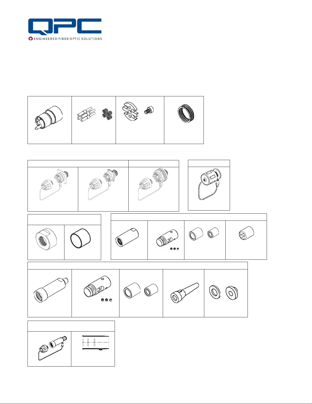
TOOL LIST
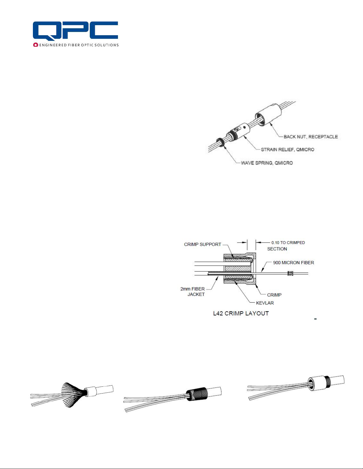
TORQUE TABLE
Component
Strain Relief Set Screws
Torque Values
48 – 53 in-lb 48 – 53 in-lb 3 – 4 in-lb 2 – 3 in-lb
5.5 – 6.0 N • m 5.5 – 6.0 N • m .34 – .45 N • m .23 – .34 N • m
TK-060 QPC Cable and Connector Prep Tool Kit – (Equivalent tools may be used)
PT-062 Miller Kevlar Scissors (Carbon Molybdenum & Vanadium Steel Blade)
PT-500 Precise-Control .050” Screwdriver (1.27mm) Hex
PT-501 Precise-Control Screwdriver, 1/16" Hex
PT-503 Precise-Control Screwdriver, 5/64" (2mm) Hex
PT-502 Precise-Control Screwdriver, 3/32" Hex
PT-504 Precise-Control Screwdriver, 2.5mm Hex
PT-505 Screwdriver, Number 1 Phillips, 6-3/4" Overall Length
PT-506 Dial Torque-Measuring Wrench, 3/8" Square Drive, 0 to 150in.-lbs. and 0 to 18NM Torque
PT-536 Crow's Foot Wrench Adjustable 3/8" Square Drive 0.0-1.125"(0-28.57mm)
PT-545 Crow's Foot Wrench Adjustable 1/2" Square Drive .236-1.771" (6-45mm)
PT-546 3/8" Female x 1/2" Male Square Drive Adapter, Chrome
PT-532 Long-Nose Pliers with Flat Jaws, Cushion Grip, 6-3/4" Overall, Manual Jaws with Wire Cutter
PT-599 Hex Bit Set, 5 pcs (.050", 1/16", 5/64", 3/32", 2.5mm) 1/4" Shank, Overall Length 2”
PT-590 Torque-Measuring Screwdriver, Hex Drive, 2.5 to 11.5 in.-lbs. Adjustable Torque
PT-591 4" Drill Press Vise with 2 x Machined Plastic Jaws with Groove
TK-045 QPC QMicro Tool Kit – (Equivalent tools may be used)
PT-388 QMicro Torque Fixture (Plug Only)
PT-540 Hydraulic Crimping Tool
PT-541 Die Set, 0.324 Hex, Hydraulic Hand Crimper