QPC QLink User manual

CAI-QLR-01: QLink Receptacle Customer Assembly Instructions
Document:
CAI-QLR-01
Revision:
0
Release Date:
08/13/2019
Revision Date:
--/--/----
QPC Fiber Optic, LLC
www.qpcfiber.com
27612 El Lazo Road, Laguna Niguel, CA 92677
Ph: (949) 361-8855
Page 1 of 11
QLink Receptacle
Customer Assembly Instructions
Jam Nut & Flange Mount
Threaded / Hermaphroditic / Reverse Bayonet / Push Pull
DOCUMENT: CAI-QLR-01
REVISION: 0
REVISION DATE: 8/13/2019
QPC CONFIDENTIAL
THE INFORMATION CONTAINED IN THIS DOCUMENT IS THE SOLE PROPERTY
OF QPC FIBER OPTIC. ANY REPRODUCTION IN PART OR AS A WHOLE
WITHOUT THE WRITTEN PERMISSION OF QPC FIBER OPTIC IS PROHIBITED.

CAI-QLR-01: QLink Receptacle Customer Assembly Instructions
Page 2 of 11
SCOPE
This document will describe the Assembly Instructions for the QLink Receptacle Jam Nut and Flange
Mount Connector in the Threaded, Hermaphroditic, Reverse Bayonet and Push Pull configurations for all
cable sizes.
MAIN COMPONENTS
STRAIN RELIEF COMPONENTS
PUSH PULL
CONFIGURATION
BODY W/ INSERT &
DUST COVER
THREADED
CONFIGURATION
BODY W/ INSERT &
DUST COVER
HERMAPHRODITIC
CONFIGURATION
BODY W/ INSERT,
DUST COVER
& BACK NUT
REVERSE BAYONET
CONFIGURATION
BODY W/ INSERT &
DUST COVER
TERMINI OPTIONS
FIBER OPTIC
TERMINI PINS /
SOCKETS
MT FERRULES
CONTACT PINS /
SOCKETS
CRIMP
SLEEVES
BACKSHELL CONFIGURATION OPTIONS
CAP WEDGE
STRAIN RELIEF
INSERT WEDGE
STRAIN RELIEF
BASE WEDGE
STRAIN RELIEF
BACKSHELL
COVER
SPACER &
3 SET SCREWS
BACKNUT
BOOT / BEND LIMITER OPTION
BEND LIMITER
WASHER
WIRE MESH GRIP OPTION
WIRE MESH GRIP
SQUARE O-RINGS x2

CAI-QLR-01: QLink Receptacle Customer Assembly Instructions
Page 3 of 11
TOOL LIST
TK-054 QPC QLink Tool Kit – (Equivalent tools may be used)
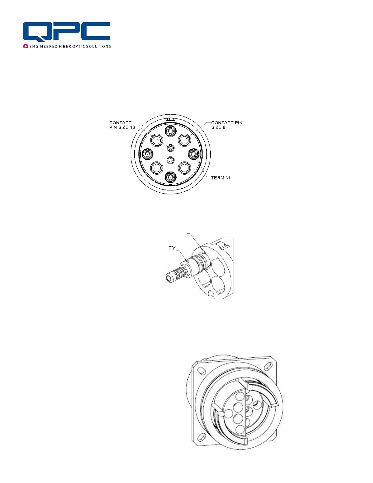
PT-117 QLink Fiber Optic Termini / Size 8 & Size 12 Contact Insertion Tool
PT-596 QLink Size 16 Contact Insertion Tool
PT-446 QLink Fiber Optic Termini Removal Tool
PT-445 QLink Size 16 Contact Removal Tool
PT-449 QLink Size 12 Contact Removal Tool
PT-443 QLink Size 8 Contact Removal Tool
PT-480 MT Fiber Optic Termini Insertion / Removal Tool
PT-005 Fiber Optic Termini Crimp Tool, 2mm, 3mm (Hex Sizes .100 / .147)
PT-560 Standard Adjustable Indent Crimp Tool M22520/1-01, Size 16 Contact
PT-562 Turret Head, Size 16, Pin and Socket, 26-14 AWG (Use with PT-560)
PT-561 Adjustable Hand Crimp Tool, Size 8 & Size 12 Contact
PT-563 Single Position Head, Size 12, Pin and Socket, 14-12 AWG (Use with PT-561)
PT-564 Single Position Head, Size 8, Pin and Socket, 12-8 AWG (Use with PT-561)
PT-589 Socket Fiber Optic Termini Sleeve Retainer Torque Tool
TK-060 QPC Cable and Connector Prep Tool Kit – (Equivalent tools may be used)
PT-062 Miller Kevlar Scissors (Carbon Molybdenum & Vanadium Steel Blade)
PT-500 Precise-Control .050” Screwdriver (1.27mm) Hex
PT-501 Precise-Control Screwdriver, 1/16" Hex
PT-503 Precise-Control Screwdriver, 5/64" (2mm) Hex
PT-502 Precise-Control Screwdriver, 3/32" Hex
PT-504 Precise-Control Screwdriver, 2.5mm Hex
PT-505 Screwdriver, Number 1 Phillips, 6-3/4" Overall Length
PT-506 Dial Torque-Measuring Wrench, 3/8" Square Drive, 0 to 150in.-lbs. and 0 to 18NM Torque
PT-536 Crow's Foot Wrench Adjustable 3/8" Square Drive 0.0-1.125"(0-28.57mm) - (For Shell Sizes 13 – 19)
PT-545 Crow's Foot Wrench Adjustable 1/2" Square Drive .236-1.771" (6-45mm) - (For Shell Sizes 21 – 31)
PT-546 3/8" Female x 1/2" Male Square Drive Adapter, Chrome
PT-532 Long-Nose Pliers with Flat Jaws, Cushion Grip, 6-3/4" Overall, Manual Jaws with Wire Cutter
PT-599 Hex Bit Set, 5 pcs (.050", 1/16", 5/64", 3/32", 2.5mm) 1/4" Shank, Overall Length 2”
PT-590 Torque-Measuring Screwdriver, Hex Drive, 2.5 to 11.5 in.-lbs. Adjustable Torque
PT-591 4" Drill Press Vise with 2 x Machined Plastic Jaws with Groove

CAI-QLR-01: QLink Receptacle Customer Assembly Instructions
Page 4 of 11
TORQUE TABLE
CABLE PREPARATION
For Cable Options with Backshell Configuration
Slide parts over cable in the following order:
1. Label (if applicable)
2. Backnut
3. Cable Grip OR Washer
4. Square O-Ring (x 2) OR Bend Limiter
5. Backshell Cover
6. Spacer
Component Backshell / Backnut Strain Relief Set Screws
Sleeve
Retainer
Shell Size 13 – 15 17 – 19 21 – 31 All All All
Torque
Values
80 – 97 in-lb 89 – 106 in-lb 106 – 124 in-lb 97 – 115 in-lb 5 – 6 in-lb 2 – 3 in-lb
9 – 11 N • m 10 – 12 N • m 12 – 16 N • m 9 – 11 N • m .56 – .68 N • m .23 – .34 N • m

CAI-QLR-01: QLink Receptacle Customer Assembly Instructions
Page 5 of 11
Strip cable jacket 6” from end. Separate Kevlar and remove any additional cable elements with Kevlar Scissors
PT-062.
Slide base of wedge strain relief back to jacket edge. Slide Insert of wedge strain relief inside base and push
between the Kevlar and the individual fibers / wires.
Cut Kevlar flush with top of wedge. Screw on Cap of Wedge Strain Relief. Torque to tighten using values from
Torque Table above.

CAI-QLR-01: QLink Receptacle Customer Assembly Instructions
Page 6 of 11
TERMINATE
For Cable Options with Backshell Configurations
Use the Stripping Length Diagrams in the Appendix located in the back of this Assembly Instruction for the
desired connector configuration to Terminate and polish the fiber and install the Electrical Contacts using
the provided Fiber Optic Termini / Contacts. For Fiber Optic / Wire Termination and Polishing details,
reference CAI-TERM-02.
For 2mm or 3mm Cable Options
Slide the Crimp Sleeve onto the cable and strip the cable according to the lengths in the diagram below for
Pin or Socket Fiber Optic Termini. Leave 5/16-Inches (8mm) of Kevlar on the cable for crimping. Thread the
bare fiber through the back of the Termini making sure that the fiber slides through the other end of the
Ferrule. Slide the Kevlar under the Crimp Sleeve. Use Fiber Optic Termini Crimp Tool PT-005 (Hex Size
.147) to crimp the Crimp Sleeve into place. For Fiber Optic / Wire Termination and Polishing details,
reference CAI-TERM-02.
Note: After Polishing Sockets, slide the Split Alignment Sleeve over the Fiber Optic Termini and then slide
the Sleeve Retainer over the Split Alignment Sleeve to the base of the Fiber Optic Termini. Apply Vibra-Tite
VC-3 Threadmate on the threads per manufacturer’s instructions. Screw the Sleeve Retainer onto the
thread of the Fiber Optic Termini. Torque using the Sleeve Retainer Torque Tool PT-589 to the torque
values in the torque table above.

CAI-QLR-01: QLink Receptacle Customer Assembly Instructions
Page 7 of 11
S2
POPULATE INSERT
Use appropriate Insertion (Tool PT-117 or PT-596) to insert Fiber Optic Termini or Contacts according to the
desired pinout (varies by connector size and channel count). Image below shows a hybrid insert.
When populating using APC Fiber Optic Termini, align the key on the Fiber Optic Termini with keyway in the
Insert.
KEYWAY
ALIGNMENT KEY
For Hermaphroditic Insert – Push in Fiber Optic Termini / Contact Pin and Sockets through back of
Insert using appropriate Insertion (Tool PT-117 or PT-596). See configuration example below.
S1, S2, S3 = Sockets for Fiber
P1, P2, P3 = Pins for Fiber
S4, S5 = Sockets for Electrical Contacts
P4, P5 = Pins for Electrical Contacts
S3
P3
P5
S5
P4
S4
P1
S1
P2

CAI-QLR-01: QLink Receptacle Customer Assembly Instructions
Page 8 of 11
Removing Pin, Socket or Contact – To remove Fiber Optic Termini from the Insert cavities, use the
Fiber Optic Termini Removal Tool PT-446. To remove Contacts from the Insert cavities, use the Contact
Removal Tool (PT-443, PT-445 or PT-449) depending upon the size of the Contacts. Insert tool from the
front and continue to compress the tool until the Fiber Optic Termini or contact ejects in the back from the
retained position. (See Image Below. Plug shown for illustrative purposes.)
For MT Insert – Use MT Termini Insertion / Removal Tool PT-480
and slip Spring Push onto the prongs on the “insert” side of the tool and push
MT Ferrule into the back cavity of the MT Insert. MT Ferrule should snap into place.

CAI-QLR-01: QLink Receptacle Customer Assembly Instructions
Page 9 of 11
Removing MT Ferrules – To remove MT
Ferrules from Insert cavities, unscrew the 4
screws from the back of the insert, remove
Insert Cap, slide the MT Ferrule out of the way,
and then use the “Remove” side of the same
tool, PT-480, to push the Spring Push out. (See
Image Below)
CONNECTOR ASSEMBLY
For Cable Options with Backshell Configurations
Slide Spacer into Body. Check the fiber length and
position by looking through the holes in the Spacer to
make sure the fiber is not twisted or kinked. Tighten
the Set Screws at the top of the Spacer using Hex
Driver PT-500. Apply Vibra-Tite VC-3 Threadmate on
the threads per manufacturer’s instructions. Use
Torque Hex Driver PT-590 with Hex Bit .050” PT-599
and torque Screws to the values in the above Torque
Table.
Pull Strain Relief to bottom of Spacer and tighten set
screws using Hex Driver PT-500. Apply Vibra-Tite
VC-3 Threadmate on the threads per manufacturer’s instructions. Then use Torque Hex Driver PT-590
with Hex Bit .050” PT-599 and torque to the values in the above Torque Table.
Perform a final visual check by looking through the holes in the Spacer to make sure that
the fiber is not twisted or kinked.

CAI-QLR-01: QLink Receptacle Customer Assembly Instructions
Page 10 of 11
STRAIN RELIEF ASSEMBLY
BOOT / BEND LIMITER OPTION:
Secure Receptacle in a 4” Drill Press Vise PT-591. Screw Backshell Cover over Spacer. Attach the
Adjustable Crow’s Foot Wrench PT-536 or PT-546 onto Dial Torque-Measuring Wrench PT-506 and torque
per values in Torque Table above. Slide Bend Limiter and Washer into place. Hand tighten Backnut to
Backshell and torque according to the values in the above Torque Table.
WIRE MESH GRIP OPTION:
Secure Receptacle in a 4” Drill Press Vise PT-591. Screw Backshell Cover over Spacer. Attach the
Adjustable Crow’s Foot Wrench PT-536 or PT-546 onto Dial Torque-Measuring Wrench PT-506 and
torque per values in Torque Table above. Slide the two pre-lubricated Square O-Rings and Wire Mesh
Cable Grip into place. Hand tighten Backnut to Backshell and torque according to the values in the above
Torque Table.
.

CAI-QLR-01: QLink Receptacle Customer Assembly Instructions
Page 11 of 11
Appendix
APPENDIX A: STRIPPING LENGTHS – QLink RECEPTACLE WITH BACKSHELL ALL SIZES
AND CONFIGURATIONS
D50110 – QLink THREADED AND REVERSE BAYONET PLUG or RECEPTACLE, FIBER OPTIC TERMINI
D50111 – QLink THREADED AND REVERSE BAYONET PLUG or RECEPTACLE, HYBRID
D50112 – QLink THREADED AND REVERSE BAYONET PLUG or RECEPTACLE, MT
D50113 – QLink HERMAPHRODITIC PLUG or RECEPTACLE, FIBER OPTIC TERMINI
D50114 – QLink HERMPHRODITIC PLUG or RECEPTACLE, HYBRID
D50115 – QLink HERMPHRODITIC PLUG or RECEPTACLE, MT
D50116 – QLink PUSH PULL PLUG or RECEPTACLE, FIBER OPTIC TERMINI
D50117 – QLink PUSH PULL PLUG or RECEPTACLE, HYBRID
D50118 – QLink PUSH PULL PLUG or RECEPTACLE, MT
APPENDIX B: QPC FIBER OPTIC – QLink CONTACT CRIMP TOOLS / SETTINGS

QPC Fiber Optic, LLC.
D50110
APPROVED
REVISIONS
DATE
REV. DESCRIPTION
CWN
CHECKED
DRAWN
DOC. NUMBER REV.
0
6/27/19
DATE DATE
SHEET 1 OF 1
QLink THREADED AND REVERSE BAYONET
PLUG or RECEPTACLE FIBER OPTIC TERMINI
CABLE PREPARATION
PROPRIETARY AND CONFIDENTIAL
THE INFORMATION CONTAINED IN
THIS DRAWING IS CONFIDENTIAL AND
THE SOLE PROPERTY OF QPC FIBER
OPTIC. ANY REPORDUCTION IN PART
OR AS A WHOLE OR DISCLOSURE OF
CONTENT WITHOUT THE WRITTEN
PERMISSION OF QPC FIBER OPTIC IS
PROHIBITED.
mm
10 20 30 40 50 60 70 80 90 100 110
3.79 [96.3]
3.64 [92.5]
SIZE 13 - 23
SIZE 25 - 31
mm
10 20 30 40 50 60 70 80 90 100 110
3.79 [96.3]
3.64 [92.5]
SIZE 13 - 23
SIZE 25 - 31 PIN TERMINI
SOCKET TERMINI
PIN TERMINI
SOCKET TERMINI
DIMENSIONS ARE IN INCH[MM].
1.19 [30.2]
0.41 [10.5]

QPC Fiber Optic, LLC.
D50111
APPROVED
REVISIONS
DATE
REV. DESCRIPTION
CWN
CHECKED
DRAWN
DOC. NUMBER REV.
0
6/27/19
DATE DATE
SHEET 1 OF 1
QLink THREADED AND REVERSE
BAYONET PLUG or RECEPTACLE, HYBRID
CABLE PREPARATION
PROPRIETARY AND CONFIDENTIAL
THE INFORMATION CONTAINED IN
THIS DRAWING IS CONFIDENTIAL AND
THE SOLE PROPERTY OF QPC FIBER
OPTIC. ANY REPORDUCTION IN PART
OR AS A WHOLE OR DISCLOSURE OF
CONTENT WITHOUT THE WRITTEN
PERMISSION OF QPC FIBER OPTIC IS
PROHIBITED.
mm
10 20 30 40 50 60 70 80 90
3.71 [94.2]
3.79 [96.2]
100
3.56 [90.3]
3.64 [92.4]
SIZE 13-23
SIZE 25-31
mm
10 20 30 40 50 60 70 80 90 100
3.85 [97.8]
3.64 [92.4]
SIZE 13-23
SIZE 25-31
4.00 [101.6]
3.79 [96.2]
PIN CONTACT
PIN TERMINI
SOCKET CONTACT
SOCKET TERMINI
PIN CONTACT
PIN TERMINI
SOCKET CONTACT
SOCKET TERMINI
DIMENSIONS ARE IN INCH[MM].
1.19 [30.2]
0.41 [10.5]

QPC Fiber Optic, LLC.
D50112
APPROVED
REVISIONS
DATE
REV. DESCRIPTION
CN
CHECKED
DRAWN
DOC. NUMBER REV.
0
6/27/19
DATE DATE
SHEET 1 OF 1
QLink THREADED AND REVERSE
BAYONET PLUG or RECEPTACLE, MT
PROPRIETARY AND CONFIDENTIAL
THE INFORMATION CONTAINED IN
THIS DRAWING IS CONFIDENTIAL AND
THE SOLE PROPERTY OF QPC FIBER
OPTIC. ANY REPORDUCTION IN PART
OR AS A WHOLE OR DISCLOSURE OF
CONTENT WITHOUT THE WRITTEN
PERMISSION OF QPC FIBER OPTIC IS
PROHIBITED.
mm
10 20 30 40 50 60 70 80 90
CABLE PREPARATION
100 110
3.64 [92.40]
DIMENSIONS ARE IN INCH[MM].
MT Ferrule w/o Pins
MT Ferrule w/ Pins

QPC Fiber Optic, LLC.
D50113
APPROVED
REVISIONS
DATE
REV. DESCRIPTION
CWN
CHECKED
DRAWN
DOC. NUMBER REV.
0
6/27/19
DATE DATE
SHEET 1 OF 1
QLink HERMAPHRODITIC PLUG or
RECEPTACLE, FIBER OPTIC TERMINI
CABLE PREPARATION
PROPRIETARY AND CONFIDENTIAL
THE INFORMATION CONTAINED IN
THIS DRAWING IS CONFIDENTIAL AND
THE SOLE PROPERTY OF QPC FIBER
OPTIC. ANY REPORDUCTION IN PART
OR AS A WHOLE OR DISCLOSURE OF
CONTENT WITHOUT THE WRITTEN
PERMISSION OF QPC FIBER OPTIC IS
PROHIBITED.
mm
10 20 30 40 50 60 70 80 90 100 110
4.12 [104.6]
4.27 [108.4]
SIZE 13 - 23
SIZE 25 - 31
SOCKET TERMINI
PIN TERMINI
SOCKET TERMINI
PIN TERMINI
DIMENSIONS ARE IN INCH[MM].
0.41 [10.5]
1.19 [30.2]
1.36 [34.4]

QPC Fiber Optic, LLC.
D50114
APPROVED
REVISIONS
DATE
REV. DESCRIPTION
CWN
CHECKED
DRAWN
DOC. NUMBER REV.
0
6/27/19
DIMENSIONS ARE IN INCH[MM].
DATE DATE
SHEET 1 OF 1
QLink HERMPHRODITIC PLUG
or RECEPTACLE, HYBRID
CABLE PREPARATION
PROPRIETARY AND CONFIDENTIAL
THE INFORMATION CONTAINED IN
THIS DRAWING IS CONFIDENTIAL AND
THE SOLE PROPERTY OF QPC FIBER
OPTIC. ANY REPORDUCTION IN PART
OR AS A WHOLE OR DISCLOSURE OF
CONTENT WITHOUT THE WRITTEN
PERMISSION OF QPC FIBER OPTIC IS
PROHIBITED.
mm
10 20 30 40 50 60 70 80 90 100 110
4.12 [104.6]
4.04 [102.6]
4.33 [110.0]
4.27 [108.4]
4.19 [106.4]
4.48 [113.8]
SIZE 13 - 23
SIZE 25 - 31
SOCKET TERMINI
PIN TERMINI
PIN CONTACT
SOCKET CONTACT
SOCKET TERMINI
PIN TERMINI
PIN CONTACT
SOCKET CONTACT
1.19 [30.2]
0.41 [10.5]

QPC Fiber Optic, LLC.
D50115
APPROVED
REVISIONS
DATE
REV. DESCRIPTION
CN
CHECKED
DRAWN
DOC. NUMBER REV.
0
06/27/19
DATE DATE
SHEET 1 OF 1
QLink HERMPHRODITIC PLUG
or RECEPTACLE, MT
PROPRIETARY AND CONFIDENTIAL
THE INFORMATION CONTAINED IN
THIS DRAWING IS CONFIDENTIAL AND
THE SOLE PROPERTY OF QPC FIBER
OPTIC. ANY REPORDUCTION IN PART
OR AS A WHOLE OR DISCLOSURE OF
CONTENT WITHOUT THE WRITTEN
PERMISSION OF QPC FIBER OPTIC IS
PROHIBITED.
mm
10 20 30 40 50 60 70 80 90
CABLE PREPARATION
100 110
4.12 [104.72]
DIMENSIONS ARE IN INCH[MM].
MT Ferrule w/o Pins
MT Ferrule w/ Pins

QPC Fiber Optic, LLC.
D50116
APPROVED
REVISIONS
DATE
REV. DESCRIPTION
CN
CHECKED
DRAWN
DOC. NUMBER REV.
0
06/27/19
DATE DATE
SHEET 1 OF 1
QLink PUSH PULL PLUG or
RECECEPTACLE FIBER OPTIC TERMINI
PROPRIETARY AND CONFIDENTIAL
THE INFORMATION CONTAINED IN
THIS DRAWING IS CONFIDENTIAL AND
THE SOLE PROPERTY OF QPC FIBER
OPTIC. ANY REPORDUCTION IN PART
OR AS A WHOLE OR DISCLOSURE OF
CONTENT WITHOUT THE WRITTEN
PERMISSION OF QPC FIBER OPTIC IS
PROHIBITED.
CABLE PREPARATION
mm
10 20 30 40 50 60 70 80 90 100 110
4.45 [113.0]
4.30 [109.2]
SIZE 13 - 23
SIZE 25 - 31
mm
10 20 30 40 50 60 70 80 90 100 110
4.45 [113.0]
4.30 [109.2]
SIZE 13 - 23
SIZE 25 - 31 SOCKET TERMINI PIN TERMINI
SOCKET TERMINI PIN TERMINI
DIMENSIONS ARE IN INCH[MM].
0.41 [10.5]
1.19 [30.2]
1.36 [34.4]

QPC Fiber Optic, LLC.
D50117
APPROVED
REVISIONS
DATE
REV. DESCRIPTION
CN
CHECKED
DRAWN
DOC. NUMBER REV.
0
06/27/19
DATE DATE
SHEET 1 OF 1
QLink PUSH PULL PLUG or
RECEPTACLE, HYBRID
PROPRIETARY AND CONFIDENTIAL
THE INFORMATION CONTAINED IN
THIS DRAWING IS CONFIDENTIAL AND
THE SOLE PROPERTY OF QPC FIBER
OPTIC. ANY REPORDUCTION IN PART
OR AS A WHOLE OR DISCLOSURE OF
CONTENT WITHOUT THE WRITTEN
PERMISSION OF QPC FIBER OPTIC IS
PROHIBITED.
CABLE PREPARATION
mm
10 20 30 40 50 60 70 80 90
4.37 [111.0]
4.45 [113.0]
100
4.22 [107.2]
4.30 [109.2]
SIZE 13-23
SIZE 25-31
mm
10 20 30 40 50 60 70 80 90 100
4.51 [114.6]
4.30 [109.2]
SIZE 13-23
SIZE 25-31
4.66 [118.4]
4.45 [113.0]
SOCKET TERMINI
PIN TERMINI
PIN CONTACT
SOCKET CONTACT
110 120 110
PIN CONTACT
PIN TERMINI
SOCKET CONTACT
SOCKET TERMINI
DIMENSIONS ARE IN INCH[MM].
1.19 [30.2]
0.41 [10.5]

QPC Fiber Optic, LLC.
D50118
APPROVED
REVISIONS
DATE
REV. DESCRIPTION
CN
CHECKED
DRAWN
DOC. NUMBER REV.
0
06/27/19
DATE DATE
SHEET 1 OF 1
QLink PUSH PULL PLUG or
RECEPTACLE, MT
PROPRIETARY AND CONFIDENTIAL
THE INFORMATION CONTAINED IN
THIS DRAWING IS CONFIDENTIAL AND
THE SOLE PROPERTY OF QPC FIBER
OPTIC. ANY REPORDUCTION IN PART
OR AS A WHOLE OR DISCLOSURE OF
CONTENT WITHOUT THE WRITTEN
PERMISSION OF QPC FIBER OPTIC IS
PROHIBITED.
mm
10 20 30 40 50 60 70 80 90
CABLE PREPARATION
100 110
4.30 [109.2]
DIMENSIONS ARE IN INCH[MM].
MT Ferrule w/o Pins
MT Ferrule w/ Pins
Table of contents
Other QPC Cables And Connectors manuals