EN
QSR SERIES USER MANUAL - REV000A 5
QSR series
3 - Introduction
3.2 - Installation requirements
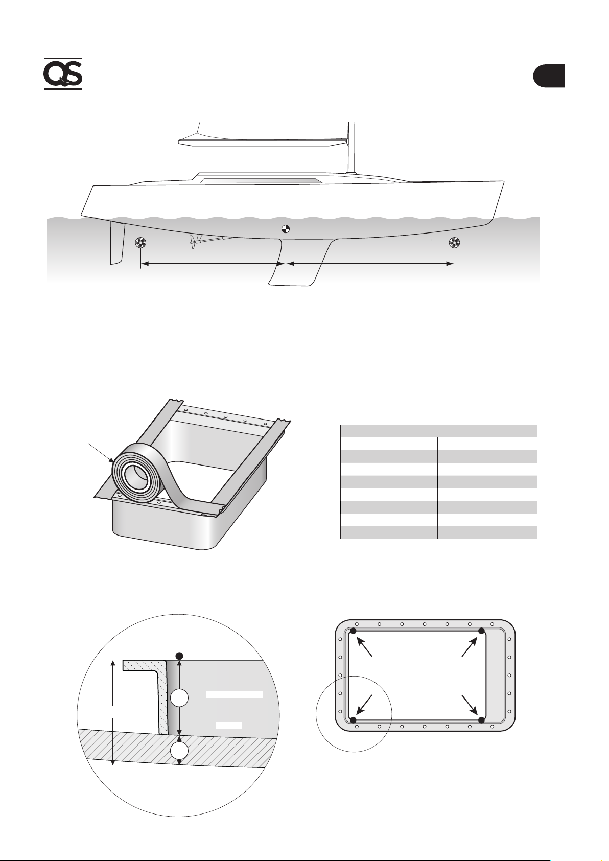
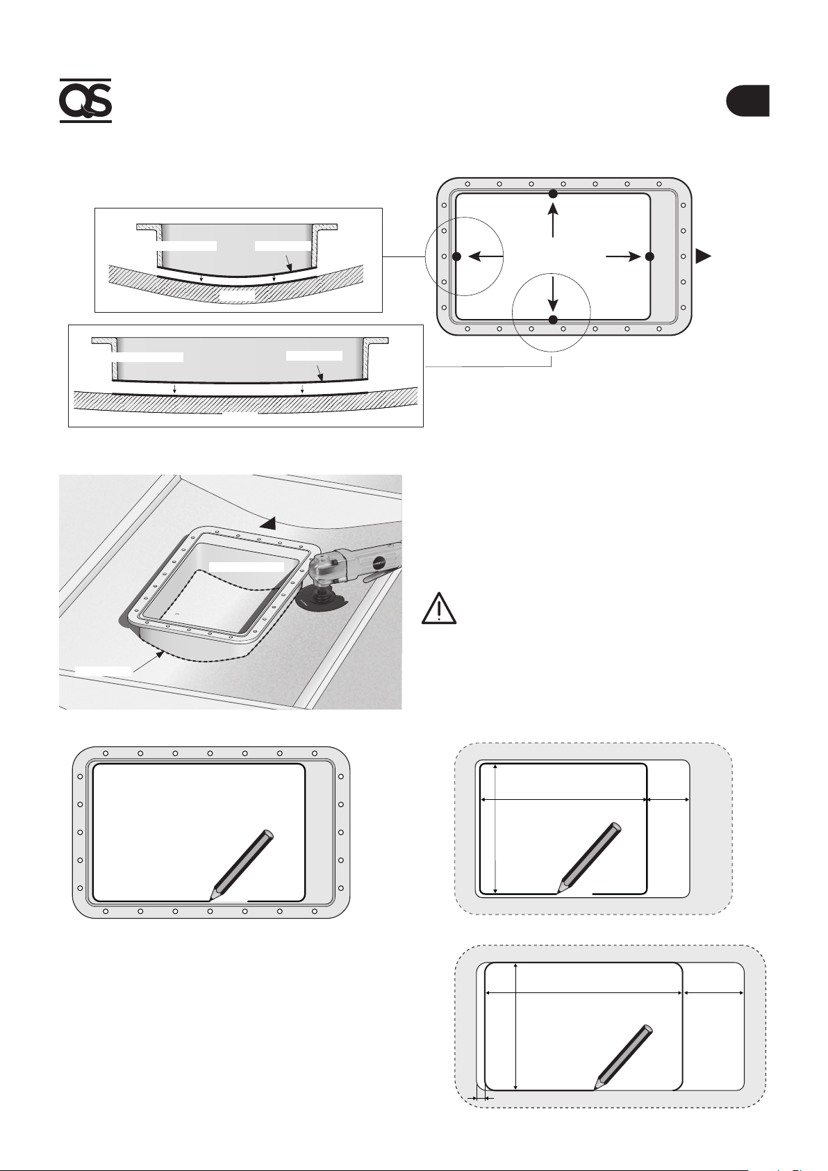
It is strongly recommended to entrust a professional with the preparation and positioning of the counter ange on
the hull. These instructions are generic and do not show by any means the details of the operations of preparing the coun-
ter ange, which falls under the competence of the shipyard. In case of problems caused by a defective installation of the
counter ange, the installer will be held responsible.
Despite all components and moving mechanical parts are of high quality, the correct installation of the propulsion unit is fun-
damental for a safe and efcient use of the boat, as well as of the propulsion unit itself.
Please note that the installation of such unit is an operation requiring experience and technical competence. It is recommend-
ed to entrust the installation to competent staff and to consult the manufacturer or naval architects to fully evaluate the entity
of the work.
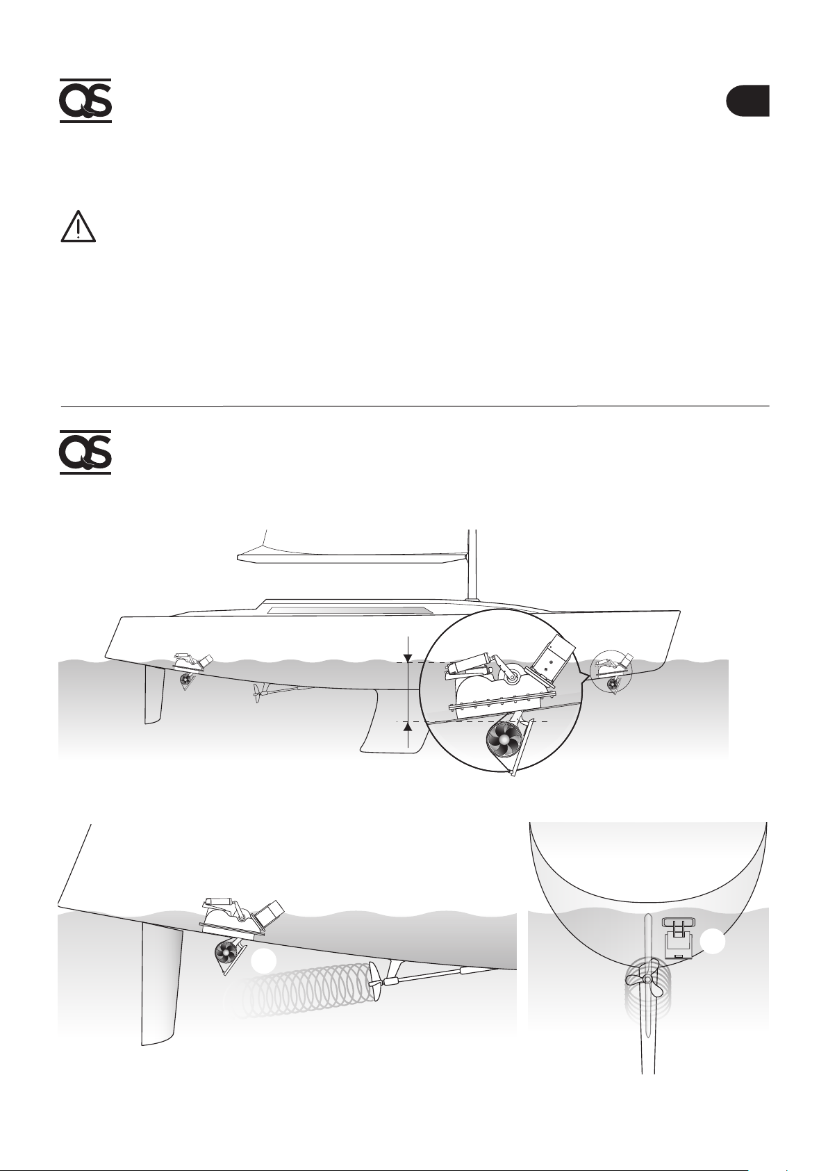
The QSR retractable thruster®has two distinct movements.
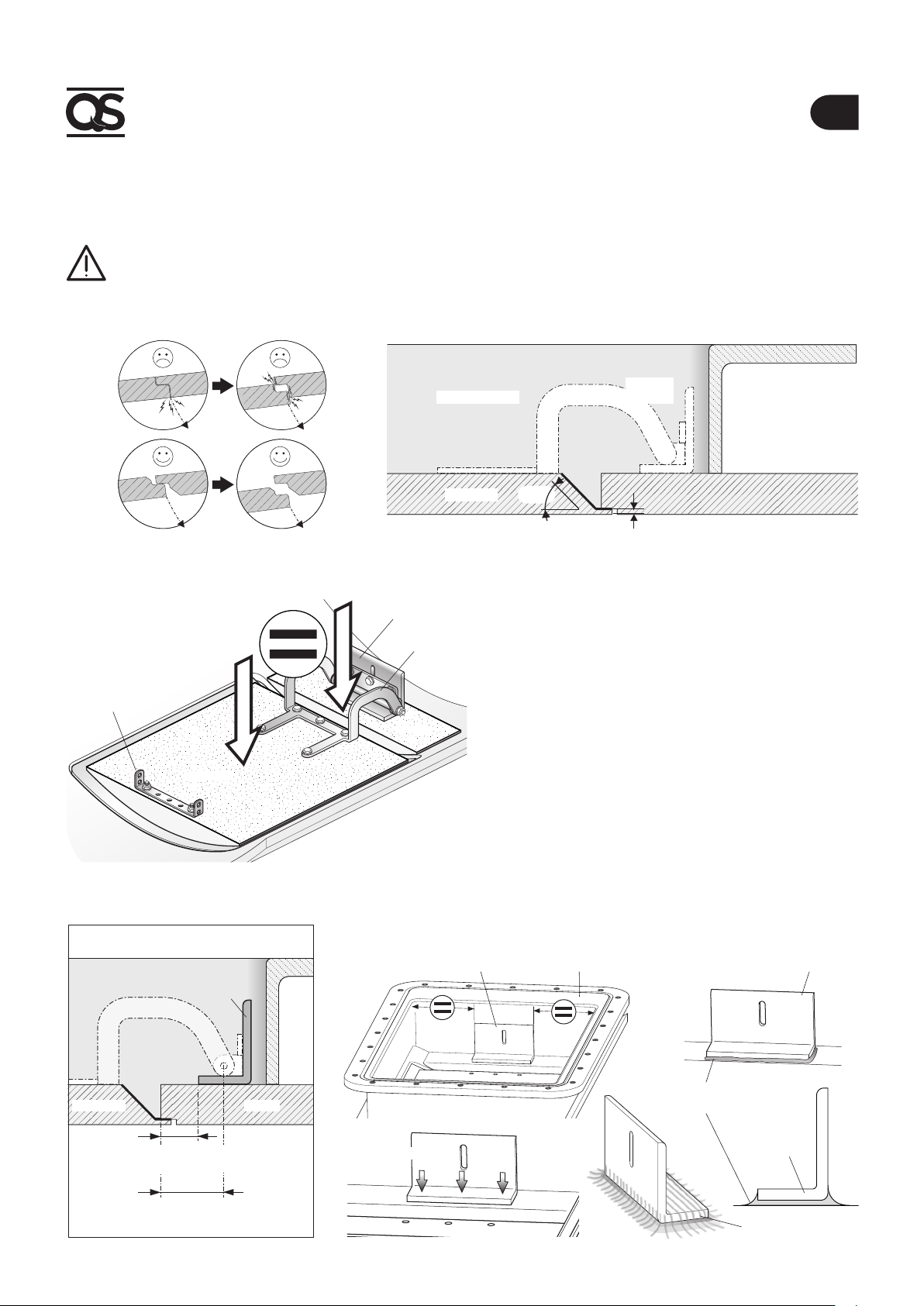
The main movement, relating to the propulsion part, is of tilting type. The hinges on which the movement happens are con-
ceived to confer high resistance to the set and are located on the at ange surface that joins the pre-assembled structure to
the hull solid support.
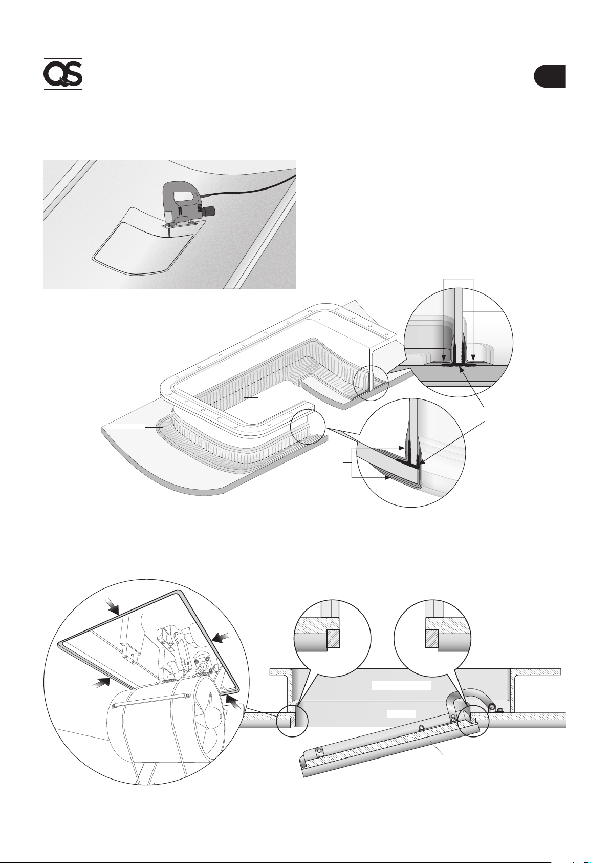
The secondary movement relates to the closing of the through-hull tting from where the tunnel comes out. This tilting
movement takes place around the hinge, which has been designed and manufactured in order to open the lid without interfer-
ences (if properly installed, as per instructions provided).
Electric motor, gear, levers and all other components are supplied by QS Seamaster®, already assembled on the sup-
porting structure in BMC and do not require adjustments, adaptations or sealings, unless indicated in this manual.
The QSR retractable thruster is sold separately from the counter ange, that can be supplied in different materials to
comply with the different types of hulls. QS Seamaster®is able to supply stainless steel, aluminium alloy or BMC supports,
fundamental for a solid and precise installation.
For the breglass hulls the support must be laminate in the hull respecting the current regulations relating to joints. The pro-
pulsion unit distributes mechanical stresses to the hull through the counter ange. The strenght of the joint will be determined
by overlapped, up to standard, rolling processes.
For aluminium alloy or for stainless steel hulls, the support must be welded to the hull.
If this installation is correctly realised, a box-type structure like the support's one, can give greater sturdiness to the hull.
Consult the manufacturer, naval architects and/or specialised companies to evaluate additional work such as beams and ribs
near the retractable propulsion unit.
This document contains the instructions that are necessary for boat manufacturers and marine equipment installers to as-
semble and commission
the Thruster.
Warning symbol concerning haz-
ardous situations.
Caution
symbol to avoid direct or indirect
damage to the product.
This manual contains Warning and/or Caution symbols that are important for safety.
Comply with the recommendations provided herein.
3.0 Important notes
F
PROCEEDING WITH THE INSTALLATION IN GOOD LIGHT CONDITIONS.
We recommend using an appropriate personal protective equipment.
QS SEAMASTER®thrusters are not suitable for installation in potentially explosive environments and/or atmos-
pheres.
Assembly and subsequent checks or repairs must only be carried out by qualified personnel..
THE PRODUCT MUST BE DISCONNECTED FROM THE ELECTRICAL SYSTEM BEFORE INSTALLING OR PROVIDING
MAINTENANCE.
QS SEAMASTER takes no responsibility regarding the inadequate connection of the users to the electrical system
and to the safety of the same.
3.1 Precautions for the installer