QSC LS118 User manual

L Class User Manual
LS118 Active Subwoofer
TD-001679-01-A
*TD-001679-01*

Contents
Explanation Of Symbols.................................................................................4
Important Safety Instructions .............................................................................4
FCC Statement. . . . . . . . . . . . . . . . . . . . . . . . . . . . . . . . . . . . . . . . . . . . . . . . . . . . . . . . . . . . . . . . . . . . . . . . . . . . . . . . . . . . . . . . .5
LS118 Subwoofer ...........................................................................................5
Warranty.............................................................................................5
Introduction...........................................................................................6
Key Features and Technologies ................................................................................6
What’s in the Box ...........................................................................................6
Features..............................................................................................7
LS118 Ground Deployment...............................................................................8
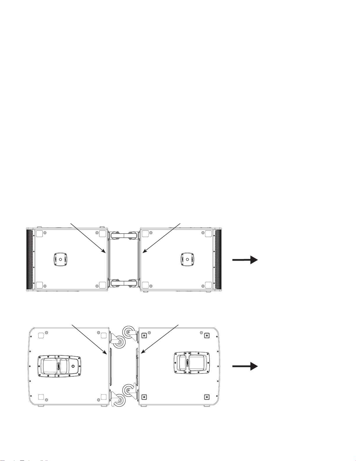
Cardioid Configurations ......................................................................................8
Best: Back-to-back ..........................................................................................8
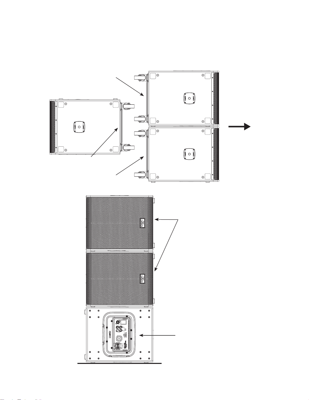
Better: Stacked .............................................................................................9
Good: Side-by Side .........................................................................................9
Three-Box Cardioid Systems .................................................................................10
Pole-Mounting Loudspeakers over a Subwoofer. . . . . . . . . . . . . . . . . . . . . . . . . . . . . . . . . . . . . . . . . . . . . . . . . . . . . . . . . . . . . . . . . . 11
LS118 Flown Deployment ...............................................................................12
Safety ...................................................................................................12
Rigging Safety Regulations .........................................................................................12
Rules for Suspension ........................................................................................12
Using the LS118 Integrated Suspension Points ....................................................................13
LS118 Rear Panel. . . . . . . . . . . . . . . . . . . . . . . . . . . . . . . . . . . . . . . . . . . . . . . . . . . . . . . . . . . . . . . . . . . . . . . . . . . . . . . . . . . . . . 14
System Power .............................................................................................15
AC Connectors ............................................................................................15
Connecting to AC Mains ...........................................................................................15
Daisy Chaining using Power Cable Jumpers ...........................................................................16
Daisy Chaining ..................................................................................................16
Power On Sequence ..............................................................................................16
Power Off Sequence ..............................................................................................17
Audio Connections .........................................................................................17
Analog Audio .............................................................................................17
Daisy Chaining using Balanced XLR Jumper Cables .....................................................................17
Network .................................................................................................17
Daisy Chaining using Network Jumper Cables .........................................................................18
Connecting to a Network ..........................................................................................18
Control.........................................................................................................19
Dante ..........................................................................................................19

LS118 Rear Panel User Interface..........................................................................20
Navigation ...............................................................................................20
Menu Map......................................................................................................20
Home Screen ....................................................................................................20
Home Screen Status ..........................................................................................21
Menu ..........................................................................................................22
Settings ........................................................................................................22
Utilities. . . . . . . . . . . . . . . . . . . . . . . . . . . . . . . . . . . . . . . . . . . . . . . . . . . . . . . . . . . . . . . . . . . . . . . . . . . . . . . . . . . . . . . . . . . . . . . . . . . . . 22
Regulatory .................................................................................................22
Additional Functions ..............................................................................................23
DSP Features ..............................................................................................23
LS118 Accessories .........................................................................................23
Complementary Accessories .................................................................................23
LS118 Care and Maintenance ...........................................................................24
LS118 Appendix ......................................................................................24
QSC Self Help Portal .......................................................................................26
Customer Support ..........................................................................................26
Warranty.................................................................................................26

4
EXPLANATION OF SYMBOLS
The term “WARNING!” indicates instructions regarding personal safety. If the instructions are not followed, the result may be bodily
injury or death.
The term “CAUTION!” indicates instructions regarding possible damage to physical equipment. If these instructions are not followed, it
may result in damage to the equipment that may not be covered under the warranty.
The term “IMPORTANT!” indicates instructions or information that are vital to the successful completion of the procedure.
The term “NOTE” is used to indicate additional useful information.
NOTE: The intent of the lightning flash with arrowhead symbol in a triangle is to alert the user to the presence of un-
insulated “dangerous” voltage within the product’s enclosure that may be of sufficient magnitude to constitute a risk of
electric shock to humans.
NOTE: The intent of the exclamation point within an equilateral triangle is to alert the user to the presence of important
safety, and operating and maintenance instructions in this manual.
IMPORTANT SAFETY INSTRUCTIONS
WARNING!: TO PREVENT FIRE OR ELECTRIC SHOCK, DO NOT EXPOSE THIS EQUIPMENT TO RAIN OR
MOISTURE.
WARNING!: While it is possible for one person to lift a LS118 subwoofer, it is important to use proper lifting techniques.
Suggested reading: OSHA Technical Manual on Back Disorders and Injuries.
(http://www.osha.gov/dts/osta/otm/otm_vii/otm_vii_1.html#app_vii:1_2).
1. Keep these instructions.
2. Heed all warnings.
3. Follow all instructions.
4. Do not use this apparatus near water.
5. Clean only with a dry cloth.
6. Install in accordance with the manufacturer's instructions.
7. Do not install near any heat sources such as radiators, heat registers, stoves, or other apparatus (including amplifiers) that produce
heat.
8. Do not defeat the safety purpose of the polarized or grounding-type plug. A polarized plug has two blades with one wider than
the other. A grounding type plug has two blades and a third grounding prong. The wide blade or the third prong are provided for
user safety. If the provided plug does not fit into the desired outlet, consult an electrician for replacement of the obsolete outlet.
9. Protect the power cord from being walked on or pinched particularly at plugs, convenience receptacles, and the point where they
exit from the apparatus.
10. Only use attachments/accessories specified by the manufacturer.
11 . Unplug this apparatus during lightning storms or when unused for long periods of time.
12. Refer all servicing to qualified service personnel. Servicing is required when the apparatus has been damaged in any way, such as
when the power-supply cord or plug is damaged, liquid has been spilled, or objects have fallen into the apparatus, the apparatus
has been exposed to rain or moisture, does not operate normally, or has been dropped.
13. The appliance coupler, or the AC Mains plug, is the AC mains disconnect device and shall remain readily operable after
installation.

5
14. Adhere to all applicable, local codes.
15. Consult a licensed, professional engineer when any doubt or questions arise regarding a physical equipment installation.
16. Suspension of this product should be done by qualified persons following safe rigging practices. Other limitations may apply.
17. Use only the recommended system components and suspension hardware intended for use with this product as directed by this
manual.
FCC Statement
LS118 Subwoofer
NOTE: The LS118 has been tested and found to comply with the limits for a Class B digital device, pursuant to Part 15 of
the FCC Rules.
These limits are designed to provide reasonable protection against harmful interference in a residential installation. This equipment
generates, uses and can radiate radio frequency energy and, if not installed and used in accordance with the instructions, may cause
harmful interference to radio communications. However, there is no guarantee that interference will not occur in a particular installation.
If this equipment does cause harmful interference to radio or television reception, which can be determined by turning the equipment off
and on, the user is encouraged to try to correct the interference by one or more of the following measures:
• Reorient or relocate the receiving antenna.
• Increase the separation between the equipment and receiver.
• Connect the equipment into an outlet on a circuit different from that to which the receiver is connected.
• Consult the dealer or an experienced radio/TV technician for help.
Warranty
For a copy of the QSC Limited Warranty, visit the QSC website at www.qsc.com.
NOTE: Read and follow these instructions carefully. If the subwoofer(s) is not suspended properly, it could fall, causing
personal injury and damage to the equipment. Please refer to the Flown Deployment chapter of the User Manual for rules
on suspension.

6
Introduction
L Class represents the next generation of advanced, intelligent, active loudspeakers/subwoofers for applications ranging from simple,
portable, plug-and-play setups, to demanding, networked, high-tech AV productions and fixed installations.
The LS118 active subwoofer features a brilliant combination of leading-edge innovation, refined engineering and unparalleled ease of
use in an easy-to-deploy package.
Key Features and Technologies
• Very high output (136 dB peak SPL) with impressive low frequency performance
• Purpose-designed, 460 mm (18-inch) long excursion direct radiating driver
• Energy-efficient, 3600 W peak power Class D amplifier module with Power Factor Correction and extremely low AC consumption
• Acoustic Linear Phase (ALP) design provides complementary coherence between QSC loudspeakers/subwoofers deployed in the
same audio system delivering a uniform listening experience across the entire venue.
• QSC SysNav™(System Navigator) App allows the user to easily design, configure, control, monitor and apply signal processing to
individual subwoofers, full arrays or groupings of both.
• Network solution includes digital audio-over-IP (Dante®) for interoperability with other audio equipment and seamless control and
monitoring integration into the Q-SYS Ecosystem via Q-SYS Inventory Extensions.
• Omni-directional or cardioid radiation modes (cardioid setup requires min. 2 units)
• Selectable DEEP™mode for extremely low frequency extension
• Rugged painted wood enclosure for lasting durability
• Four low-noise, heavy-duty casters
• Vertical or horizontal deployments (M20 threaded pole receivers) combined with array frame/ground-stack adapters or
loudspeaker poles.
• Complemented by LA108 and LA112 active line array loudspeakers
• Industry-best global 6-Year Extended Warranty with product registration.
What’s in the Box
(1) LS118 Active
Subwoofer unit
(1) AC power cord, with
PowerCON®TRUE1
(3 m / 10 ft) connectors
(1) Quick Start Guide (1) Safety Sheet
TD-001655-00

7
Features
Front
Bottom
Right Side
Left Side
Back
Top
—Figure1—
6
6
7
1
3
4
2
8
8
5
1. Alignment cups for stacking
2. Four low-noise, heavy-duty casters
3. Amplifier protection/Temporary Weather Shield (TWS) accessory attachment ring
4. Dual M20 threaded socket for 35 mm loudspeaker pole
5. Slip-resistant feet - four on the bottom
6. Slip-resistant feet - four on the side
7. Front power LED
8. Cast aluminum handles
9. Amplifier power module and controls
10. M10 attachment points - four on the top
11 . M10 attachment - four on the side
4
10
10
11
11
9
6
6

8
LS118 Ground Deployment
The LS118 active subwoofer can be used as a single low-frequency acoustic source or in multiples for additional low-frequency
reproduction levels.
A simple, practical rule-of-thumb is to use one subwoofer for every two top loudspeakers deployed. The simplest setup consists of
placing a single subwoofer between a pair of loudspeakers. For practical reasons, it is often necessary to place the subwoofer on one
side, which will usually also produce satisfactory results.
Placing subwoofers to the left and right sides of a stage is often convenient, but it tends to create a concentration of low frequency
energy in the middle of the audience area (often named “Power Alley”). To prevent this, try clustering all subwoofers in the left/right
middle of the stage, or spread them evenly across the front of the stage.
Cardioid Configurations
Two or more LS118 active subwoofers can be arranged and configured to produce a cardioid radiation pattern very simply, with no
complex calculations or processing settings required. The processing necessary for cardioid operation is already programmed into
each LS118 unit’s DSP. On each subwoofer facing forward (toward the audience), select FORWARD on the Cardioid menu. On each
subwoofer facing away from the audience, select REAR on the Cardioid menu. Put the same audio signal into both subwoofers and set
the same gain on each one.
Best: Back-to-back
Placing the subwoofers back-to-back offers the best cardioid performance, with 15 dB of sound attenuation to the rear. Figure 2 is a
top view of two LS118 active subwoofers oriented vertically and placed back-to-back. Figure 3 also is a top view of a back-to-back
arrangement, but with the subwoofers oriented horizontally.
—Figure2—
—Figure3—
Cardiod > Rear
Cardiod > Rear
Cardiod > Forward
Cardiod > Forward

9
Better: Stacked
Stacking two LS118 active subwoofers is similar to the side-by-
side arrangement. Place the rear-facing subwoofer on the bottom.
Good: Side-by Side
Placing the LS118 active subwoofers side-by-side may save space
but creates a less precise cardioid pattern.
Floor
Cardiod > Forward
Front View
(as seen from the
audience)
—Figure4—
Cardiod > Rear
—Figure5—
Cardiod > Rear
Top View
Toward
Audience
Cardiod > Forward

10
Three-Box Cardioid Systems
A three-box array, with two forward-facing subwoofers and one rear-facing subwoofer, gives additional acoustic output to the front
but with slightly less optimal rear attenuation.
Figure 6 is a top view of a back-to-back three-box array.
Figure 7 is a front view of a stacked three-box array. Use the bottom subwoofer as the rear-facing one.
Cardiod > Forward
Cardiod > Forward
Cardiod > Rear
Toward
Audience
—Figure6—
Front View
(as seen from the audience)
—Figure7—
Floor
Cardiod > Rear
Cardiod > Forward

11
Pole-Mounting Loudspeakers over a Subwoofer
The LS118 active subwoofer is equipped with two M20 threaded pole sockets: one on the top, and one on the side.
Use the tables below to determine which poles are safe to use with LA108/LA112 loudspeakers and an LS118 subwoofer in horizontal
or vertical orientations.
LS118 Config LA108 LA108
x2
LA108
x3 L A 112 LA112
x2 KLA12 KLA12
x2 KW153 KW152 KW122 K12.2 CP12
Single Subwoofer
Vertical
36-in Pole 4 4 6 4 6 4 6 6 4 4 4 4
Vertical
26-in Pole 4 4 4 4 4 4 6 4 4 4 4 4
Horizontal
36-in Pole 444444444444
Horizontal
26-in Pole 444444444444
Double Subwoofer
Horizontal
26-in Pole 444444444444
Horizontal
16-in Pole 444444444444

12
LS118 Flown Deployment
Safety
WARNING!: Before placing, installing, rigging, or suspending any loudspeaker/subwoofer product, inspect all
hardware, suspension, cabinets, transducers, brackets, and associated equipment for damage. Any missing, corroded,
deformed, or non-load rated component could significantly reduce the strength of the installation or placement. Any such
condition severely reduces the safety of the installation and should be immediately corrected. Use only hardware which is
rated for the loading conditions of the installation and any possible short-term, unexpected overloading.
Never exceed the rating of the hardware or equipment.
Consult a licensed, professional engineer regarding physical equipment installation. Ensure that all local, state, and
national regulations regarding the safety and operation of loudspeakers/subwoofers and related equipment are
understood and adhered to.
Rigging Safety Regulations
• 2006/42/EC
• EN ISO 12100-1: 2004
• EN1991-1 / EN1993-1-1 / EN1993-1-8 / EN1999-1-1
• DGUV Vorschrift 17/18
• ANSI E1.8-2018
Rules for Suspension
• Consult a professional mechanical or structural engineer, licensed in the jurisdiction of the sound system installation, to review,
verify, and approve all attachments to the building or structure.
• Employ the services of a certified, professional rigger for hoisting, positioning, and attaching the equipment to the supporting
structure.
• Correct use of all suspension hardware and components is imperative in sound system suspension and deployment.
• Always calculate suspended loads before lifting to make sure suspension components and hardware are used within their
respective load limits.
• Consult local codes and regulations to fully understand the requirements for suspended loads in the venue in which the equipment
will be suspended.
• Use only dedicated QSC M10 Eyebolt Kit-S for suspending the subwoofer. Further details can be found below.
• Be absolutely certain of the integrity of any structural member intended to support suspended loads. Hidden structural members
can have hidden structural weakness.
• Never assume anything! Owner or third-party supplied suspension attachment points may not be adequate for suspending the
loads.
• Before lifting, always inspect all components (enclosures, suspension brackets, pins, frames, bolts, nuts, slings, shackles, etc.) for
cracks, wear, deformation, corrosion, or missing, loose, or damaged parts that could reduce the strength of the assembly. Discard
any worn, defective, or suspect parts and replace them with new, appropriately load-rated parts.
• Consult a professional mechanical or structural engineer, licensed in the jurisdiction of the sound system installation, to review,
verify, and approve all attachments to the building or structure. Employ the services of a certified, professional rigger for hoisting,
positioning, and rigging the equipment to the supporting structure.

13
Using the LS118 Integrated Suspension Points
WARNING!: Only a single LS118 can be safely suspended
utilizing the QSC M10 Eyebolt Kit-S (sold separately). DO NOT
attempt to suspend additional loudspeakers or subwoofers
underneath the LS118 subwoofer.
The LS118 has M10 bolt points on both the top and the sides of the
subwoofer and can be deployed in either direction, based on the space or
visual requirements of the installation.
1. Use a 6 mm hex key to remove the four hex screws from the four
LS118M10 installation points on the top or side of the subwoofer.
2. Thread an eye bolt into each of the threaded inserts.
3. Tighten the eye bolts until their shoulders are snug against the enclosure.
4. Continue to rotate the eye bolts until they reach the desired position.
Do not over-tighten, as that may damage the eye bolt thread or the
threaded insert.
5. The subwoofer is ready for suspension. —Figure8—

14
LS118 Rear Panel
—Figure9—
8
79
3
1
4
2
131211
10
56
14
1. Full color screen displays Menus and Settings
2. Rotary encoder to adjust gain, select values, and press for enter
3. Push to enter the Menu, or return to Home Screen from Menu
4. Push to ID subwoofer in SysNav™or Q-SYS Ecosystem
5. Dual-switch EtherCON connections to SysNav™and/or Dante®-enabled system
6. Balanced analog input connection for line level sources
7. Parallel (Through) balanced analog output connection of the balanced input
8. PowerCON TRUE1 locking AC Power inlet
9. PowerCON TRUE1 locking AC Power pass-through
10. Indicates that signal is present on the associated input
11 . Indicates that the subwoofer is powered on
12. Indicates Standby Mode
13. Indicates that the subwoofer DSP is limiting
14. Variable speed ventilation fan

15
System Power
The LS118 power module does not include a power switch. This is done to prevent an array from being suspended and a
loudspeakers'/subwoofers' power switch inadvertently bumped or left in the off position. To power a subwoofer on/off, either switch
the AC supply at the source or twist the AC POWER-IN connector clockwise or counter-clockwise to power each subwoofer on/off.
For safety reasons, it is important to follow the proper power cable connection/disconnection sequence to power on or off
loudspeakers and subwoofers.
Proper power on/off sequencing can help to prevent undesirable sounds from being introduced into the loudspeaker/subwoofer
system (pops, clicks, thumps). Always follow the rule that loudspeakers/subwoofers are “last on, first off.”
WARNING!: The LS118 employs a universal power supply capable of operating the system with input AC power
voltages ranging from 100 – 240 VAC at 50 – 60 Hz. Make sure to only use the power cable that is appropriate for the
location of deployment.
AC Connectors
The LS118 Subwoofer features dual powerCON TRUE1 AC connectors to support daisy-chaining multiple loudspeakers/subwoofers
within an array or for ground-stacking deployments.
Neutrik powerCON TRUE1 AC connectors have become standard in the AV
production industry and are often found on lighting systems and portable LED walls.
PowerCON TRUE1 connector benefits:
• 16 Amp current capacity
• Safe connection/disconnection under load
• POWER-IN and POWER-OUT locking connectors can couple to create
extension cables — without the need for a separate barrel connector
• IP65 rating for ingress protection (once coupled)
Connecting to AC Mains
1. Insert the locking POWER-IN cable connector of the supplied power cable into
the INLET connector on the rear panel.
2. Twist the cable connector clockwise until it locks in place. Twisting the connector
also turns power on/off for that box (and any subsequent daisy-chained boxes).
3. Plug the other end of the power cable into the appropriate AC Mains power
source.
4. Array will power on automatically once the AC Mains power has been connected.
—Figure10—
PowerCON TRUE1 AC connectors

16
Daisy Chaining using Power Cable Jumpers
The LS118 subwoofer features loop-through power connection using powerCON
TRUE1 connectors. The powerCON TRUE1 cable and connector system is rated for
a maximum current draw of 16 amps. In most countries, this is sufficient to power a
maximum of three (3) LS118 subwoofers from a single connection to the AC mains
supply (see chart below for more details by country voltage).
When not in use, the powerCON INLETS and OUTLETS connectors located on the
subwoofers' rear panel should be covered by the weather-resistant flaps.
Neutrik powerCON TRUE1 loop-through cables are not included with LS118
subwoofers but may be purchased separately from most professional audio
equipment suppliers or from QSC.
• LS-KIT-J (International Jumper Kit: includes 2x 120 cm PowerCON jumpers and
2x 120 cm EtherCON jumpers, 1.5 mm2/H05VV cables)
• LA-KIT-J-NA (North America Jumper Kit: includes 2x 48-in PowerCON jumpers
and 2x 48-in EtherCON jumpers, 12 AWG/SVT cables – NEC compliant)
WARNING!: The amplifier AC mains power is present in the loop-
through cables. If the AC mains is connected to one LS118 subwoofer,
electrical power is present on all connected loop-through cables.
WARNING!: Do not connect more than four (4) LS118 subwoofers
together using the jumper power cables (one AC mains power cord
and three jumper cables). When using jumper power cables, make all
loop-through connections prior to connecting to the AC mains.
Daisy Chaining
1. Insert the locking POWER-OUT connector of the jumper cable (not included)
fully into the OUTLET connector on the rear panel. Twist clockwise until it locks in place.
2. Insert the locking POWER-IN connector into the INLET connector on the rear panel of the next loudspeaker/subwoofer in the
chain. Twist clockwise until it locks in place.
3. Repeat until all subwoofers in the array (up to four, using three loop-through jumper cables) are properly connected.
Please follow the table below for safely powering each array:
Model Input Current (normal use) 100V (15A circuit) 220~140V (10A circuit)
LS118 100V = 3A
120 V = 3A
220~240V = 1.5A
Up to 4x subwoofers
Total 12A
Up to 4x subwoofers
Total 6A
WARNING!: Always ensure there is 20% headroom when daisy-chaining AC power to multiple boxes. For example,
never load more than 12 Amps on a 120 V/15 A circuit, or 8 Amps on an 230 V/10 A circuit.
Power On Sequence
1. Turn down the output levels on the mixer (or other audio source) to its minimum position.
2. Switch on all source devices (CD players, mixers, instruments).
3. Apply power to the LS118 subwoofer last, twisting the locking POWER-IN connector clockwise. If the LS118 subwoofers are daisy-
chained to other boxes, then power only needs to be applied to the first box in the chain.
4. Verify that power has been applied to each loudspeaker/subwoofer. When a unit powers on, the green STANDBY indicator
LED and the red LIMIT indicator LED on the rear panel illuminates. After a few seconds, the red LIMIT indicator and the yellow
STANDBY LEDs dim, and the blue POWER indicator LED illuminates.
—Figure11—
Weather-resistant flaps

17
Power Off Sequence
1. Turn down the output levels on the mixer (or other audio source) to its minimum position.
2. Disconnect power to the LS118 subwoofer first, twisting the locking POWER-IN connector counter-clockwise. If the LS118
subwoofers are daisy-chained to other boxes, power only needs to be disconnected from the first box in the chain.
3. Verify that power connections have been disconnected on each box. When the blue POWER indicator LED and yellow Standby
LED are no longer illuminated, it is safe to proceed.
4. Power off all audio source devices.
Audio Connections
NOTE: While digital audio and analog audio can be physically connected simultaneously, the subwoofer will default to
digital audio if a Dante®audio connection is made, rendering the analog audio inputs muted until the Dante®signal is
disconnected. The analog connections can be used alongside a line array that is ethernet connected for QSC SysNav™
control, as standalone without SysNav control, or as a backup audio connection in the event of digital audio failure.
Analog Audio
Each subwoofer features a LINE IN (input) XLR and a LINE OUT (output) XLR to support daisy-
chaining multiple loudspeakers/subwoofers in an array.
The LINE OUT XLR connector is wired in parallel to the LINE IN XLR connector, making it a direct
passthrough. It does not output any Post-DSP signal, nor is the level on the LINE OUT affected by
the digital GAIN setting adjusted on the subwoofer.
Using the XLR connectors, subwoofers can be safely daisy-chained up to any combination of
eight(8) subwoofers or top boxes without any signal loss.
NOTE: It is not recommended to use unbalanced audio
connections with LS118 subwoofers. Always use XLR balanced
audio connections and wiring as shown in Figure 13.
Daisy Chaining using Balanced XLR Jumper Cables
1. Connect the audio source (such as a mixing console) to the LINE IN
XLR connector (6) on the rear panel.
2. If daisy-chaining additional boxes in the array, connect the audio loop-through jumper cable (not supplied) from the LINE OUT
XLR connector to the LINE IN XLR connector on the next loudspeaker/subwoofer.
3. Continue this process until all loudspeakers/subwoofers in the array are connected using balanced XLR cables.
Network
The dual network connectors also support daisy-chaining multiple loudspeakers/subwoofers in an array. Unlike the powerCON and
XLR connectors which have dedicated input and throughput connectors, the network ports are identical switched ethernet ports, which
means either can be used as an input or as a network hop to the next box in the array.
The network ports can accept a rugged etherCON connector or a standard RJ45 connector; however, etherCON type connectors are
recommended, rather than conventional RJ45 connectors, as the mechanical robustness and EMC performance is superior.
Each subwoofer includes two IP addresses, one dedicated for Control and one dedicated for Dante audio-over-IP; however, both
Control and Dante data traffic are carried over a single CAT5/6 cable into a single RJ45 port.
LINE IN
LINE OUT
—Figure12—
—Figure13—

18
Daisy Chaining using Network Jumper Cables
There are two common methods for connecting network devices:
a. Star Topology: In this method, each device has its own port on an ethernet switch. This is the most robust method, but it requires
a cable home run from each device back to the ethernet switch, which is suitable for permanent installations but challenging for
temporary deployments.
b. Daisy-Chaining: This method requires dual switched ports on each device, as found on the L Class loudspeakers and subwoofers.
While daisy-chaining is much easier to deploy, it should be noted that each “hop” incurs a latency penalty, measured in micro-
seconds that quickly add up. Therefore, a pre-determined latency is applied to each Dante receiving device to account for switch
hops, eliminating the risk of dropped packets and resulting audio glitches.
The Dante latency settings are based on worst case latency assumptions and are therefore conservative. The L Class loudspeakers/
subwoofers default to 1 ms which will accommodate up to 10 switch hops.
As a reference point, a Dante mixer connected through an ethernet switch to a 6-box daisy-chained array of LS118 subwoofers, is the
equivalent of 6 switch hops.
If there are 5 switch hops or fewer, there is the potential to adjust the latency down from 1 ms to 0.5 ms, using the Dante Controller
software. Please refer to Audinate for more information on Dante Controllers.
For ethernet daisy-chaining, the optional LS-KIT-J or LS-KIT-J-NA jumper kit will need to be ordered (refer to the Accessories section for
more information).
Connecting to a Network
1. Connect the network source (router, switch or computer) to the RJ45 jack on the rear
panel using a CAT5/6 cable (not supplied)
2. If using the RJ45 loop-through connections, connect another CAT6 cable to the
available RJ45 port on the first loudspeaker/subwoofer, and connect the open-end
connector to the RJ45 input on the next loudspeaker/subwoofer.
3. Continue this process until all loudspeakers/subwoofers in the array are connected
using RJ45 digital connections.
—Figure14—

19
Control
There are two modes of operation using network control:
a. Indirect Mode: This mode duplicates functionality of the Rear User Interface (RUI), allowing Ethernet connection to just one box.
Low data communication to the other boxes is managed via wireless transmission (QSC AWARE™).
NOTE: Do NOT use Indirect Mode for Firmware updates.
b. Direct mode: This mode offers greater functionality, but it requires Ethernet connection to every box in the array. When all boxes
in the array are discovered on the network, Indirect mode is disabled. To update Firmware, there must be Ethernet connections to
each box.
An Array can be controlled and monitored using one of two software applications:
a. QSC SysNav™(System Navigator): This Windows application is available from QSC.com and allows the user to discover,
control, and monitor each loudspeaker/subwoofer within the array. SysNav also manages Firmware updates.
b. QSC Q-SYS Designer™: This Windows application is available from QSC.com and allows the user to discover, control, and
monitor each loudspeaker/subwoofer within the array.
NOTE: Q-SYS Designer requires a Q-SYS Core to fully function. More information on Q-SYS Designer is available from
the online Helpfile https://q-syshelp.qsc.com/
Dante
Each array of loudspeakers/subwoofers can subscribe to a Dante audio-over-IP Transmitter (TX), sent over the network from common
audio sources such as a digital mixing console or a QSC Q-SYS Core. Dante subscriptions can be set up using one of two methods:
a. QSC SysNav™(System Navigator): This Windows application is available from QSC.com and allows the user to view all Dante
Transmitters (TX) discovered on the network and subscribe a loudspeaker/subwoofer (or an array) to that transmitter.
b. Dante Controller: This Windows or macOS application is available from Audinate.com and provides users with a more advanced
tool to managing Dante traffic.

20
LS118 Rear Panel User Interface
Navigation
When first unpacking the LS118 active subwoofer, make sure to download the latest subwoofer firmware as well as the latest version of
the QSC SysNav™(System navigator) App from QSC.com.
Menu Map
Security
Sub
Crossover
(UPF)
Sensitivity LED Mode
DEEP CardioidEQDelay
LCD
Brightness
Settings
Network UtilitiesRegulatory
HOME
—Figure15—
Home Screen
The Home screen is visible after the subwoofer has powered on and booted up completely. If any changes are made via the user
interface, users can return to the Home screen from any menu parameter by pressing the Menu button twice or waiting 30 seconds.
1. Rotate to adjust gain on HOME screen, or select values in the MENU. Press to
confirm a selected value.
2. Press to access the MENU from the HOME screen, or press while in the MENU to
return to the HOME screen.
3. Press ID button to identify subwoofer location when connected to QSC SysNav™
or Q-SYS Ecosystem
4. Information on Subwoofer and Status
5. Security lock status of the subwoofer display
6. Current Gain level for the subwoofer
7. Status (LPF) of the subwoofer crossover display
8. Status of the onboard architectural delay display
9. Status of the on-board EQ display
10. Status of the DEEP™mode display
11 . Status of Cardioid Mode display
12. Network icon displays if the subwoofer is connected to the active network
13. Current Input Sensitivity setting display
—Figure16—
12
2
1
7
5
3
13
4
6
8
10
11
9
Table of contents
Other QSC Subwoofer manuals

QSC
QSC KS212C User manual

QSC
QSC KS Series User manual

QSC
QSC SB-5218 User manual

QSC
QSC SB-1180 User manual

QSC
QSC AcousticDesign QSC-AD-C81TW-WH User manual

QSC
QSC AcousticDesign AD-S28Tw User manual

QSC
QSC ModularDesign Subwoofer MD-S215 User manual

QSC
QSC GP212-sw User manual

QSC
QSC ISIS 215SB User manual

QSC
QSC WideLine WL218-sw User manual

QSC
QSC SB-2180 User manual

QSC
QSC SB-5218 User manual

QSC
QSC GP218-sw User manual

QSC
QSC AcousticDesign AD-C81TW User manual

QSC
QSC SF-3 User manual

QSC
QSC KS118 User manual

QSC
QSC ISIS 215PCM User manual

QSC
QSC SB-5218 User manual

QSC
QSC ACOUSTICDESIGN AD-S28TW-BK User manual

QSC
QSC AcousticDesign AD-C81TW User manual